STM32 Analogue-to-Digital Converter (ADC)
|
|
ADC Clock
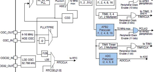
Shown below is the STM32F10x clock tree. Notice some areas are highlighted. Check them out because these are related to the ADC block.
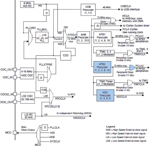
STM32 ADC Clock Tree
We can clearly see that the ADC peripheral is connected to the APB2 peripheral bus. If you can recall from my earlier post on STM32’s clock options then you’ll remember that APB2 can run at 72MHz speed which is by the way the maximum operating speed for STM32F10x series MCUs. ST recommends that the ADC be feed with no more than a 14MHz clock. Thus we should make sure that ADC clock is in the range of 600 kHz to 14MHz. Since it takes about 14 cycles to process ADC data the maximum possible number of conversions per second is one million. I previously pointed out in one of my posts that MikroC’s IDE provided an easy to use tool to configure clocks for various STM32 peripheral buses. I recommend using this tool to configure peripheral clocks rather than coding them on your own. Pay attention particularly to APB1, APB2 and PCLK2 clocks when setting clock for the ADC block. Wrong settings will lead to unpredictable/erratic behaviours. 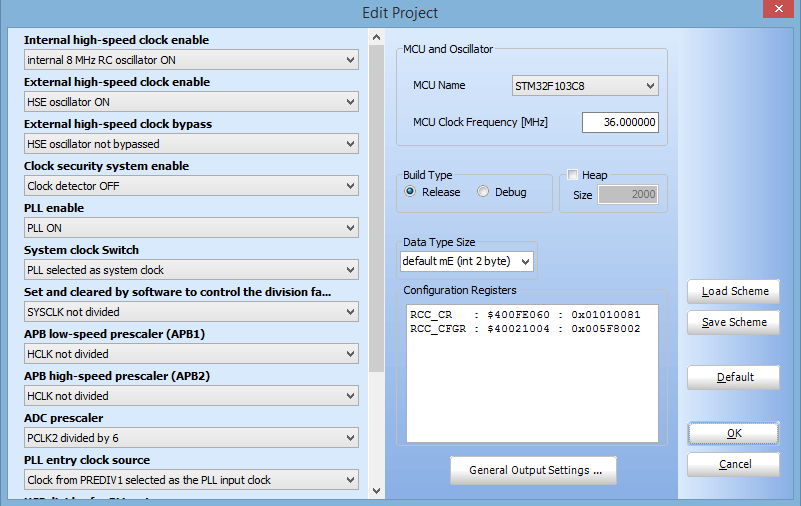 Additionally you can use STM32CubeMX to verify if your clock configuration is okay. You can also use this software to check which I/O pins belong to which ADC channels and much more. However be aware, STM32CubeMX is not yet compatible with MikroC compiler. Personally I rarely use it.
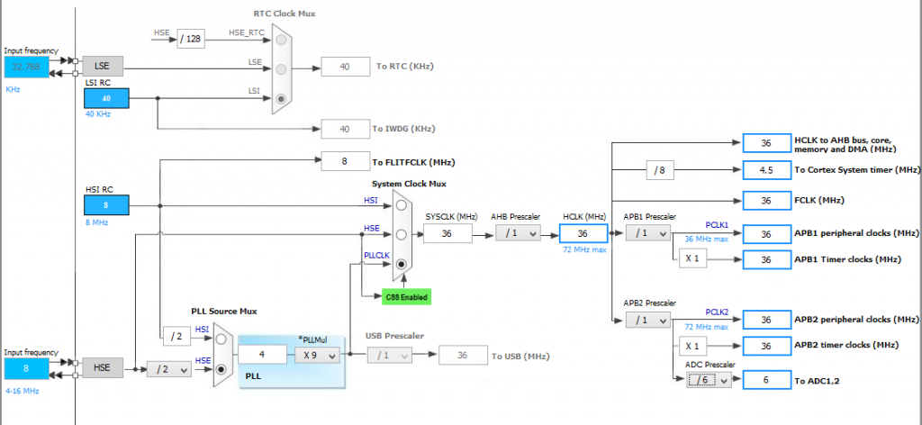
The ADC Registers
There are several registers associated with each ADC unit. At first you may feel like getting lost in an ocean of 32-bit registers. However things aren’t so. Of these there are two ADC control registers called ADC_CR1 and ADC_CR2 that set ADC properties and mode of operation. There’s a status register, ADC_SR which flags important ADC events like end of a conversion, etc. These are the most important ones. I’m not going to explain every bit because they are well explained in the reference manual. 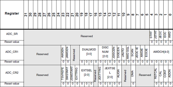 The next set of registers are responsible for specifying channel sequence, sequence length, sampling times, offset and holding ADC conversion results. While dealing with the STM32 ADC block, you’ll come across the letter J before many stuffs. These stuffs signify that they are related to inJected group channels only. The rest of the stuffs are mostly related to regular groups and common uses. ADC_SQRx registers specify channel sequences. There are three of these registers and of them ADC_SQR1 also specifies the number of channels in a regular sequence. ADC_SQR3 through ADC_SQR1 are sequentially feed with channel numbers according to position in a given sequence. The injected group equivalent of the ADC_SQRx is the single ADC_JSQR register. ADC_SMPR1 and ADC_SMPR2 registers specify the sampling times of each channel. The sampling time is common to both regular and injected groups. ADC_LTR and ADC_HTR registers hold the lower and upper analogue watchdog ADC count limits respectively. Again these are common for both groups. ADC_JOFRx registers hold offset values for injected channels. The values in them are automatically subtracted from injected channel ADC conversion results. Lastly the ADC_DR and ADC_JDRx registers hold ADC conversion results for regular and injected groups respectively. ADC_DR is common for all regular group channels. There are four ADC_JDRx registers for four injected channels. Recall that there can be up to four ADC channels for an injected group. When coding there’s no need to follow any specific sequence for programming registers. Just make sure you coded for the required ones correctly.
My Version of Standard Peripheral Library
Unlike any of my previous posts on STM32, I’m moving a bit faster toward coding section rather than giving detailed explanations at all steps. To fully realize the ADC block’s various functionalities you need to code and experience it right after you have understood it. As I stated earlier, this block is a very complex one. It was not possible for me to give examples of every possible combination of operating modes. I’m here presenting only the basics needed to get started with STM32’s ADC. I would highly recommend readers to read this document from ST: http://www.st.com/web/en/resource/technical/document/application_note/CD00258017.pdf and read the reference manual for STM32F10x series for more details. Even after all these, this is a mega post. None of my previous posts on STM32 is so long. We all know that when it comes to handling 32-bit registers of 32-bit micros, programming turns into tiles of a tricky puzzle. Another big headache for programmers is the coding of registers with numeric jargons. I don’t know for sure if it is for these reasons or for some others that most STM32 users are SPL dependent. Almost no one codes STM32s at raw level. MikroC compiler simplifies things a lot of stuffs in several areas. It is easy to get started with it no matter if you are an expert or a novice. Personally I like MikroC compiler more than any other compiler for several reasons. I didn’t want to change it when I planned to play with STM32-based ARM micros. When I finally chose MikroC for ARM over other more popular and widely used compilers like Keil and Coocox, I was aware of SPL’s advantages and what I would go through next for selecting so. I wondered how to get rid of handling 32-bit registers effectively and at the same time develop a strategy to avoid memorizing the functional uses and names of different registers. I was looking for something similar to SPL that can be easily integrated with MikroC compiler. Personally I don’t like to use ST’s SPL and so I coded my version of SPL. From now on I’ll be sharing my version of SPL codes with my posts. I recommend readers to check them out before using them. Just for demo, check out my basic library for GPIO configuration:
//I/O Modes
#define input_mode 0x00
#define output_mode_low_speed 0x02
#define output_mode_medium_speed 0x01
#define output_mode_high_speed 0x03
//I/O Configurations
#define GPIO_PP_output 0x00
#define GPIO_open_drain_output 0x04
#define AFIO_PP_output 0x08
#define AFIO_open_drain_output 0x0C
#define analog_input 0x00
#define floating_input 0x04
#define input_without_pull_resistors 0x04
#define digital_input 0x08
//Pull Resistor Configurations
#define pull_down 0x00
#define pull_up 0x01
//Miscellaneous
#define enable 0x01
#define disable 0x00
//CR Register Configuration Macro
#define pin_configure_low(reg, pin_no, io_type) do{reg &= (~(0xF << (pin_no << 2))); reg |= (io_type << (pin_no << 2));}while(0)
#define pin_configure_high(reg, pin_no, io_type) do{reg &= (~(0xF << ((pin_no - 8) << 2))); reg |= (io_type << ((pin_no - 8) << 2));}while(0)
//Bitwise Operations for GPIOs
#define bit_set(reg, bit_value) (reg |= (1 << bit_value))
#define bit_clr(reg, bit_value) (reg &= (~(1 << bit_value)))
#define get_bits(reg, mask) (reg & mask)
#define get_input(reg, bit_value) (reg & (1 << bit_value))
//Pull Resistor Functions
#define pull_up_enable(reg, pin_no) (reg |= (1 << pin_no))
#define pull_down_enable(reg, pin_no) (reg &= (~(1 << pin_no)))
//GPIO Enabling Functions
#define enable_GPIOA(mode) RCC_APB2ENRbits.IOPAEN = mode
#define enable_GPIOB(mode) RCC_APB2ENRbits.IOPBEN = mode
#define enable_GPIOC(mode) RCC_APB2ENRbits.IOPCEN = mode
#define enable_GPIOD(mode) RCC_APB2ENRbits.IOPDEN = mode
#define enable_GPIOE(mode) RCC_APB2ENRbits.IOPEEN = mode
#define enable_GPIOF(mode) RCC_APB2ENRbits.IOPFEN = mode
#define enable_GPIOG(mode) RCC_APB2ENRbits.IOPGEN = mode
Now suppose you want to configure GPIO pins with this library. You can do so like this:
pin_configure_low(GPIOA_CRL, 6, (analog_input | input_mode));
pin_configure_high(GPIOB_CRH, 15, (GPIO_PP_output | output_mode_low_speed));
Now you can see that you don’t need to handle 32-bit registers, bit positions and possible combinations of bit values. In fact sometimes you won’t have remember the names of registers at all. All of these things are replaced with something more meaningful and easy to understand. Unlike ST’s SPL you don’t even have to be a programming wiz to use these libraries. Please check the header files for better understanding. At this point I must specify that I single headedly developed this idea and the libraries themselves. It took several months to develop, code, test and implement them. I tried my level best to keep things error-free and as per reference manuals. There could be some unintentional flaws in them. Should you spot one please notify me for correction.
|
|
Hi,
Simply I need like this: Kindly help me.
For example, I will have 3 adc channels need to be read as per my choice without wasting uC runtime and using interrupt, for example, i have coded here which i typically use in all projects with other uCs,
I need similar thing in STM32 but confused with too many options.
Could you suggest the right way here ?
ISR_intr_vector;
ADR_ISR()
{
static byte channel;
if(channel==0)
{
adcvalue = ADCVALUE from STM;
channel = 1;
}
else if(channel==1)
{
adcvalue = ADCVALUE from STM;
channel = 2;
}
else if(channel==2)
{
adcvalue = ADCVALUE from STM;
channel = 0;
}
channelregofstm32 = channel;
}
Hi,
Thanks for the great post. Do you have a version of your spl library for stm32f407?
thanks
Currently I’m focused towards the STM32F1xx series only…. After completing the tutorials of this series I’ll be going for the STM32F4 series…. Thanks…. 🙂
Great tutorial, thanks for the explanations! Is the DMA post already out? Would be very much appreciated.
Working on it but can’t say when it’ll be published…. Thanks…. 🙂
nice tutorial but you coding looks a bit compiicated for beginners
Thanks…. STM32 or any ARM family is not meant for beginners…. These families of complex micros are intended for high level works and so the learning curve is very steep…. It’s the best I could do rather than making tutorials with magic hexadecimal numbers and funny register names….