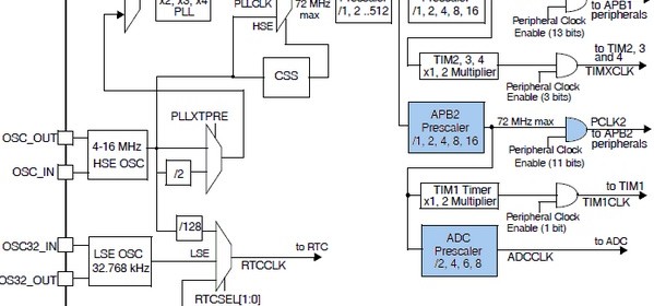
STM32 Analogue-to-Digital Converter (ADC)
|
|
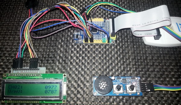
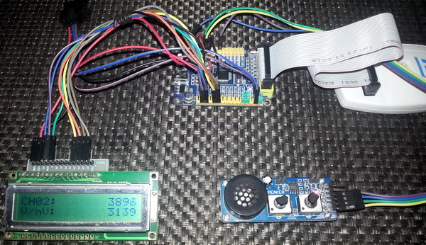
Single Channel Continuous Conversion Mode
This is similar to the third ADC example but this one is based on polling method rather than end of conversion interrupt-based one. This example is another basic example but I would prefer interrupt-based ADC conversion rather than this one as it will slow down other tasks.
#include "ADC.h"
#include "GPIO.h"
sbit LCD_RS at GPIOB_ODR.B1;
sbit LCD_EN at GPIOB_ODR.B2;
sbit LCD_D4 at GPIOB_ODR.B12;
sbit LCD_D5 at GPIOB_ODR.B13;
sbit LCD_D6 at GPIOB_ODR.B14;
sbit LCD_D7 at GPIOB_ODR.B15;
void setup();
void GPIO_init();
void ADC_init();
unsigned int read_ADC1();
void lcd_print(unsigned char x_pos, unsigned char y_pos, unsigned int value);
float map(float v, float x_min, float x_max, float y_min, float y_max);
void main()
{
unsigned int adc_data = 0;
float V = 0.0;
setup();
while(1)
{
bit_set(GPIOC_ODR, 13);
delay_ms(10);
adc_data = read_ADC1();
V = map(adc_data, 0, 4095, 0, 3300);
lcd_print(13, 1, adc_data);
lcd_print(13, 2, V);
bit_clr(GPIOC_ODR, 13);
delay_ms(90);
};
}
void setup()
{
GPIO_init();
ADC_init();
LCD_Init();
LCD_Cmd(_LCD_CLEAR);
LCD_Cmd(_LCD_CURSOR_OFF);
lcd_out(1, 1, "CH02:");
lcd_out(2, 1, "V/mV:");
}
void GPIO_init()
{
enable_GPIOA(enable);
enable_GPIOB(enable);
enable_GPIOC(enable);
pin_configure_low(GPIOA_CRL, 2, (analog_input | input_mode));
pin_configure_high(GPIOC_CRH, 13, (GPIO_PP_output | output_mode_low_speed));
}
void ADC_init()
{
ADC1_Enable();
clr_ADC1_settings();
set_ADC_mode(independent_mode);
set_ADC1_data_alignment(right_alignment);
set_ADC1_scan_conversion_mode(disable);
set_ADC1_continuous_conversion_mode(enable);
set_ADC1_regular_number_of_conversions(1);
set_ADC1_sample_time(sample_time_41_5_cycles, 2);
set_ADC1_regular_sequence(1, 2);
set_ADC1_external_trigger_regular_conversion_edge(SWSTART_trigger);
ADC1_calibrate();
start_ADC1();
}
unsigned int read_ADC1()
{
while(ADC1_SRbits.EOC == 0);
return (ADC1_DR & 0x0FFF);
}
void lcd_print(unsigned char x_pos, unsigned char y_pos, unsigned int value)
{
unsigned char tmp = 0;
tmp = (value / 1000);
lcd_chr(y_pos, x_pos, (tmp + 48));
tmp = ((value / 100) % 10);
lcd_chr_cp((tmp + 48));
tmp = ((value / 10) % 10);
lcd_chr_cp((tmp + 48));
tmp = (value % 10);
lcd_chr_cp((tmp + 48));
}
float map(float v, float x_min, float x_max, float y_min, float y_max)
{
return (y_min + (((y_max - y_min)/(x_max - x_min)) * (v - x_min)));
}
 Demo video link: https://www.youtube.com/watch?v=8fh1-rkpFAw.
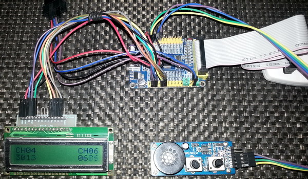
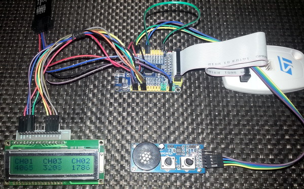
Multi-Single Channel Single Conversion Mode
This example is similar to the 4th example of this post but instead of reading a single channel multiple single channels with different sampling times are read. It is useful when you need to read multiple channels without scanning them.
#include "ADC.h"
#include "GPIO.h"
sbit LCD_RS at GPIOB_ODR.B1;
sbit LCD_EN at GPIOB_ODR.B2;
sbit LCD_D4 at GPIOB_ODR.B12;
sbit LCD_D5 at GPIOB_ODR.B13;
sbit LCD_D6 at GPIOB_ODR.B14;
sbit LCD_D7 at GPIOB_ODR.B15;
void setup();
void GPIO_init();
void ADC_init();
unsigned int read_ADC1(unsigned char channel, unsigned char sample_time);
void lcd_print(unsigned char x_pos, unsigned char y_pos, unsigned int value);
void main()
{
unsigned int ch_a = 0;
unsigned int ch_b = 0;
unsigned int ch_c = 0;
setup();
while(1)
{
ch_a = read_ADC1(1, sample_time_239_5_cycles);
ch_b = read_ADC1(3, sample_time_1_5_cycles);
ch_c = read_ADC1(2, sample_time_28_5_cycles);
lcd_print(1, 2, ch_a);
lcd_print(7, 2, ch_b);
lcd_print(13, 2, ch_c);
bit_set(GPIOC_ODR, 13);
delay_ms(10);
bit_clr(GPIOC_ODR, 13);
delay_ms(90);
};
}
void setup()
{
GPIO_init();
ADC_init();
LCD_Init();
LCD_Cmd(_LCD_CLEAR);
LCD_Cmd(_LCD_CURSOR_OFF);
lcd_out(1, 1, "CH01 CH03 CH02");
}
void GPIO_init()
{
enable_GPIOA(enable);
enable_GPIOB(enable);
enable_GPIOC(enable);
pin_configure_low(GPIOA_CRL, 1, (analog_input | input_mode));
pin_configure_low(GPIOA_CRL, 2, (analog_input | input_mode));
pin_configure_low(GPIOA_CRL, 3, (analog_input | input_mode));
pin_configure_high(GPIOC_CRH, 13, (GPIO_PP_output | output_mode_low_speed));
}
void ADC_init()
{
ADC1_Enable();
clr_ADC1_settings();
set_ADC_mode(independent_mode);
set_ADC1_data_alignment(right_alignment);
set_ADC1_continuous_conversion_mode(disable);
set_ADC1_regular_number_of_conversions(1);
set_ADC1_external_trigger_regular_conversion_edge(SWSTART_trigger);
ADC1_calibrate();
start_ADC1();
}
unsigned int read_ADC1(unsigned char channel, unsigned char sample_time)
{
ADC1_JSQR = 0x00000000;
ADC1_SQR1 = 0x00000000;
ADC1_SQR2 = 0x00000000;
ADC1_SQR3 = 0x00000000;
ADC1_SMPR1 = 0x00000000;
ADC1_SMPR2 = 0x00000000;
set_ADC1_regular_sequence(1, channel);
set_ADC1_sample_time(sample_time, channel);
set_ADC1_regular_conversions(enable);
while(ADC1_SRbits.EOC == reset);
return (0x0FFF & ADC1_DR);
}
void lcd_print(unsigned char x_pos, unsigned char y_pos, unsigned int value)
{
unsigned char tmp = 0;
tmp = (value / 1000);
lcd_chr(y_pos, x_pos, (tmp + 48));
tmp = ((value / 100) % 10);
lcd_chr_cp((tmp + 48));
tmp = ((value / 10) % 10);
lcd_chr_cp((tmp + 48));
tmp = (value % 10);
lcd_chr_cp((tmp + 48));
}
 Demo video link: https://www.youtube.com/watch?v=hcGHQFFkdfs.
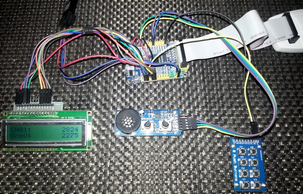
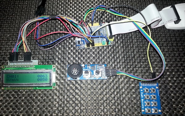
External Interrupt Triggered Single Channel Single Conversion Mode
Up till now the ADC trigger was given from the software end. However STM32 micros can perform ADC conversions when triggered externally by some other hardware. In this example, an external interrupt pin is used to trigger a single ADC conversion. After completing an ADC conversion the ADC halts. We can also use timer events as trigger sources too.
#include "ADC.h"
#include "GPIO.h"
#include "AFIO.h"
#include "Ex_Int.h"
sbit LCD_RS at GPIOB_ODR.B1;
sbit LCD_EN at GPIOB_ODR.B2;
sbit LCD_D4 at GPIOB_ODR.B12;
sbit LCD_D5 at GPIOB_ODR.B13;
sbit LCD_D6 at GPIOB_ODR.B14;
sbit LCD_D7 at GPIOB_ODR.B15;
register unsigned int adc_data = 0;
void setup();
void GPIO_init();
void ADC_init();
void interrupts_init();
void lcd_print(unsigned char x_pos, unsigned char y_pos, unsigned int value);
float map(float v, float x_min, float x_max, float y_min, float y_max);
void void EXTI11_ISR()
iv IVT_INT_EXTI15_10
ics ICS_AUTO
{
if(read_pending_reg(11) != 0)
{
bit_set(GPIOC_ODR, 13);
delay_ms(10);
bit_clr(GPIOC_ODR, 13);
pending_clr(11);
}
}
void void ADC1_ISR()
iv IVT_INT_ADC1_2
ics ICS_AUTO
{
adc_data = (ADC1_DR & 0x0FFF);
}
void main()
{
float v = 0;
setup();
while(1)
{
v = map(adc_data, 0, 4095, 0, 3300);
lcd_print(13, 1, adc_data);
lcd_print(13, 2, v);
};
}
void setup()
{
GPIO_init();
ADC_init();
LCD_Init();
interrupts_init();
LCD_Cmd(_LCD_CLEAR);
LCD_Cmd(_LCD_CURSOR_OFF);
lcd_out(1, 1, "CH01:");
lcd_out(2, 1, "V/mV:");
}
void GPIO_init()
{
enable_GPIOA(enable);
enable_GPIOB(enable);
enable_GPIOC(enable);
pin_configure_low(GPIOA_CRL, 1, (analog_input | input_mode));
pin_configure_high(GPIOC_CRH, 13, (GPIO_PP_output | output_mode_medium_speed));
pin_configure_high(GPIOB_CRH, 11, (digital_input | input_mode));
pull_up_enable(GPIOB_ODR, 11);
}
void ADC_init()
{
ADC1_Enable();
clr_ADC1_settings();
set_ADC_mode(independent_mode);
set_ADC1_data_alignment(right_alignment);
set_ADC1_scan_conversion_mode(disable);
set_ADC1_continuous_conversion_mode(disable);
set_ADC1_sample_time(sample_time_71_5_cycles, 1);
set_ADC1_external_trigger_regular_conversion_edge(EXTI_11_trigger);
set_ADC1_regular_number_of_conversions(1);
set_ADC1_regular_sequence(1, 1);
set_ADC1_regular_end_of_conversion_interrupt(enable);
ADC1_calibrate();
start_ADC1();
}
void interrupts_init()
{
AFIO_enable(enable);
falling_edge_selector(11);
set_EXTI8_11(11, PB_pin);
interrupt_mask(11);
NVIC_IntEnable(IVT_INT_EXTI15_10);
NVIC_IntEnable(IVT_INT_ADC1_2);
EnableInterrupts();
}
void lcd_print(unsigned char x_pos, unsigned char y_pos, unsigned int value)
{
unsigned char tmp = 0;
tmp = (value / 1000);
lcd_chr(y_pos, x_pos, (tmp + 48));
tmp = ((value / 100) % 10);
lcd_chr_cp((tmp + 48));
tmp = ((value / 10) % 10);
lcd_chr_cp((tmp + 48));
tmp = (value % 10);
lcd_chr_cp((tmp + 48));
}
float map(float v, float x_min, float x_max, float y_min, float y_max)
{
return (y_min + (((y_max - y_min)/(x_max - x_min)) * (v - x_min)));
}
 Demo video link: https://www.youtube.com/watch?v=dT5wkXKs42E.
|
|
Hi,
Simply I need like this: Kindly help me.
For example, I will have 3 adc channels need to be read as per my choice without wasting uC runtime and using interrupt, for example, i have coded here which i typically use in all projects with other uCs,
I need similar thing in STM32 but confused with too many options.
Could you suggest the right way here ?
ISR_intr_vector;
ADR_ISR()
{
static byte channel;
if(channel==0)
{
adcvalue = ADCVALUE from STM;
channel = 1;
}
else if(channel==1)
{
adcvalue = ADCVALUE from STM;
channel = 2;
}
else if(channel==2)
{
adcvalue = ADCVALUE from STM;
channel = 0;
}
channelregofstm32 = channel;
}
Hi,
Thanks for the great post. Do you have a version of your spl library for stm32f407?
thanks
Currently I’m focused towards the STM32F1xx series only…. After completing the tutorials of this series I’ll be going for the STM32F4 series…. Thanks…. 🙂
Great tutorial, thanks for the explanations! Is the DMA post already out? Would be very much appreciated.
Working on it but can’t say when it’ll be published…. Thanks…. 🙂
nice tutorial but you coding looks a bit compiicated for beginners
Thanks…. STM32 or any ARM family is not meant for beginners…. These families of complex micros are intended for high level works and so the learning curve is very steep…. It’s the best I could do rather than making tutorials with magic hexadecimal numbers and funny register names….