STM32 Analogue-to-Digital Converter (ADC)
|
|
Coding and Explanations
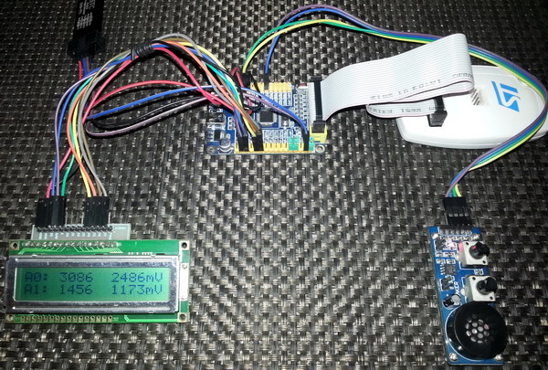
The more we code, the better picture we’ll get about the STM32’s ADC. At some point, you’ll feel that the codes are self-explanatory. For demo purposes I used a STM32F103C8T6 micro embedded in a cheap STM32 test board. The basic connection looks like this: 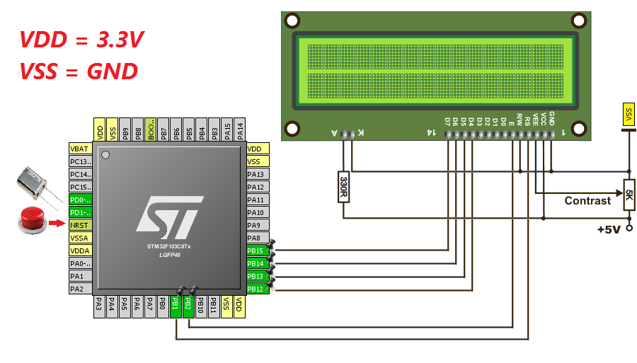 All of the stuffs above except the connections for the ADC inputs and the LCD exist in most development boards. ADC pins are typically attached with GPIOA port.
MikroC ADC Library
Obviously the first example is based on MikroC’s ADC library. MikroC compiler provided an easy to use ADC library. With this library you can do basic ADC readings and set up ADC units easily with minimum coding. MikroC’s built-in ADC library functions are as follows:
MikroC IDE’s help section explains the purpose of these function.
sbit LCD_RS at GPIOB_ODR.B1;
sbit LCD_EN at GPIOB_ODR.B2;
sbit LCD_D4 at GPIOB_ODR.B12;
sbit LCD_D5 at GPIOB_ODR.B13;
sbit LCD_D6 at GPIOB_ODR.B14;
sbit LCD_D7 at GPIOB_ODR.B15;
void setup();
unsigned int adc_avg(unsigned char no_of_samples, unsigned char channel);
void lcd_print(unsigned char x_pos, unsigned char y_pos, unsigned int value);
float map(float v, float x_min, float x_max, float y_min, float y_max);
void main()
{
unsigned char s = 0;
register unsigned int adc_data = 0;
float v = 0.0;
setup();
while(1)
{
for(s = 0; s <= 1; s++)
{
adc_data = adc_avg(10, s);
v = map(adc_data, 0, 4095, 0, 3300);
lcd_print(5, (s + 1), adc_data);
lcd_print(11, (s + 1), v);
}
GPIOC_ODRbits.ODR13 ^= 1;
delay_ms(600);
};
}
void setup()
{
GPIO_Clk_Enable(&GPIOA_BASE);
GPIO_Clk_Enable(&GPIOB_BASE);
GPIO_Clk_Enable(&GPIOC_BASE);
GPIO_Config(&GPIOA_BASE, (_GPIO_PINMASK_0 | _GPIO_PINMASK_1), (_GPIO_CFG_MODE_ANALOG | _GPIO_CFG_PULL_NO));
GPIO_Config(&GPIOC_BASE, _GPIO_PINMASK_13, (_GPIO_CFG_MODE_OUTPUT | _GPIO_CFG_SPEED_MAX | _GPIO_CFG_OTYPE_PP));
ADC1_init();
LCD_Init();
LCD_Cmd(_LCD_CLEAR);
LCD_Cmd(_LCD_CURSOR_OFF);
lcd_out(1, 1, "A0:");
lcd_out(2, 1, "A1:");
lcd_out(1, 15, "mV");
lcd_out(2, 15, "mV");
}
unsigned int adc_avg(unsigned char no_of_samples, unsigned char channel)
{
unsigned long avg = 0;
unsigned char samples = no_of_samples;
while(samples > 0)
{
avg += ADC1_Get_Sample(channel);
samples--;
}
avg /= no_of_samples;
return avg;
}
void lcd_print(unsigned char x_pos, unsigned char y_pos, unsigned int value)
{
unsigned char tmp = 0;
tmp = (value / 1000);
lcd_chr(y_pos, x_pos, (tmp + 48));
tmp = ((value / 100) % 10);
lcd_chr_cp((tmp + 48));
tmp = ((value / 10) % 10);
lcd_chr_cp((tmp + 48));
tmp = (value % 10);
lcd_chr_cp((tmp + 48));
}
float map(float v, float x_min, float x_max, float y_min, float y_max)
{
return (y_min + (((y_max - y_min)/(x_max - x_min)) * (v - x_min)));
}
In this demo I just showed how to use MikroC’s built-in ADC library functions to initialize, get average ADC counts from two ADC channels and show both ADC counts and voltage levels of each channel on a LCD display. Just a piece of cake. Not much to explain. 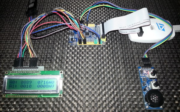
 Demo video: https://www.youtube.com/watch?v=TwMTOLkWt-Q.
Analogue Watchdog
One of the cool feature of STM32 micros is the Analogue Watchdog (AWD) unit. In traditional micros, a programmer needs to add an if-else clause to monitor if the ADC readouts are within some predefined limits. There are, therefore, some coding and resource involved. The AWD unit of STM32 micros can monitor if an ADC channel or all ADC channels are exceeding or within predefine upper and lower ADC count limits. In this way we can effectively set an analogue voltage level window for the ADC block. Thus this unit allows users to easily implement signal level monitors, zero-crossing detectors, analogue comparators and many other stuffs. Thanks to ST for hardcoding this useful feature with the ADC block. 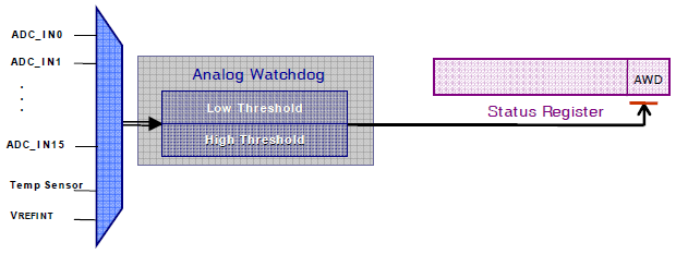 The upper and lower limit 12-bit values are stored in the High Threshold (HTR) and Lower Threshold (LTR) registers respectively. When the analogue input to be monitored is within these limits or inside guarded zone the AWD unit stays idle. When it is the other way around, the AWD wakes up. An AWD event interrupt can be generated if the AWD interrupt is enabled.
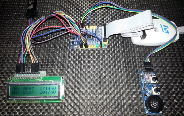
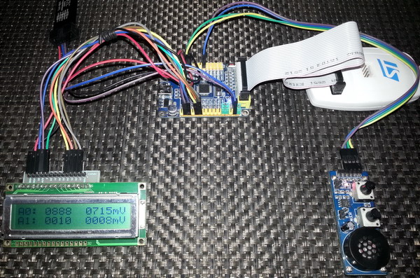
 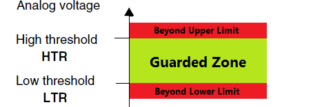 Setting AWDSGL bit, AWDEN bit and JAWDEN bit in the ADC_CR1 select which channel types the AWD unit would monitor. The demo code for AWD is just same as the previous one but this time the AWD is also used to monitor all regular ADC channels. If the ADC readings exceed the guarded zone of 400 to 3695 ADC counts, the AWD fires. This mark starts to blink a LED connected to PC13, indicating an AWD event.
sbit LCD_RS at GPIOB_ODR.B1;
sbit LCD_EN at GPIOB_ODR.B2;
sbit LCD_D4 at GPIOB_ODR.B12;
sbit LCD_D5 at GPIOB_ODR.B13;
sbit LCD_D6 at GPIOB_ODR.B14;
sbit LCD_D7 at GPIOB_ODR.B15;
#define high_level 3695
#define low_level 400
void setup();
unsigned int adc_avg(unsigned char no_of_samples, unsigned char channel);
void lcd_print(unsigned char x_pos, unsigned char y_pos, unsigned int value);
float map(float v, float x_min, float x_max, float y_min, float y_max);
void main()
{
unsigned char s = 0;
register unsigned int adc_data = 0;
float v = 0.0;
setup();
while(1)
{
for(s = 0; s < 2; s++)
{
adc_data = adc_avg(20, s);
v = map(adc_data, 0, 4095, 0, 3300);
lcd_print(5, (s + 1), adc_data);
lcd_print(11, (s + 1), v);
}
if(ADC1_SRbits.AWD == 1)
{
GPIOC_ODRbits.ODR13 ^= 1;
ADC1_SRbits.AWD = 0;
}
else
{
GPIOC_ODRbits.ODR13 = 0;
}
delay_ms(400);
};
}
void setup()
{
GPIO_Clk_Enable(&GPIOA_BASE);
GPIO_Clk_Enable(&GPIOB_BASE);
GPIO_Clk_Enable(&GPIOC_BASE);
GPIO_Config(&GPIOA_BASE, (_GPIO_PINMASK_0 | _GPIO_PINMASK_1), (_GPIO_CFG_MODE_ANALOG | _GPIO_CFG_PULL_NO));
GPIO_Config(&GPIOC_BASE, _GPIO_PINMASK_13, (_GPIO_CFG_MODE_OUTPUT | _GPIO_CFG_SPEED_MAX | _GPIO_CFG_OTYPE_PP));
ADC1_init();
ADC1_LTR = low_level;
ADC1_HTR = high_level;
ADC1_CR1bits.AWDEN = 1;
LCD_Init();
LCD_Cmd(_LCD_CLEAR);
LCD_Cmd(_LCD_CURSOR_OFF);
lcd_out(1, 1, "A0:");
lcd_out(2, 1, "A1:");
lcd_out(1, 15, "mV");
lcd_out(2, 15, "mV");
}
unsigned int adc_avg(unsigned char no_of_samples, unsigned char channel)
{
register unsigned long avg = 0;
unsigned char samples = no_of_samples;
while(samples > 0)
{
avg += ADC1_Get_Sample(channel);
samples--;
}
avg /= no_of_samples;
return avg;
}
void lcd_print(unsigned char x_pos, unsigned char y_pos, unsigned int value)
{
unsigned char tmp = 0;
tmp = (value / 1000);
lcd_chr(y_pos, x_pos, (tmp + 48));
tmp = ((value / 100) % 10);
lcd_chr_cp((tmp + 48));
tmp = ((value / 10) % 10);
lcd_chr_cp((tmp + 48));
tmp = (value % 10);
lcd_chr_cp((tmp + 48));
}
float map(float v, float x_min, float x_max, float y_min, float y_max)
{
return (y_min + (((y_max - y_min)/(x_max - x_min)) * (v - x_min)));
}
 Demo video link: https://www.youtube.com/watch?v=xMDIaEq-Q8o.
|
|
Hi,
Simply I need like this: Kindly help me.
For example, I will have 3 adc channels need to be read as per my choice without wasting uC runtime and using interrupt, for example, i have coded here which i typically use in all projects with other uCs,
I need similar thing in STM32 but confused with too many options.
Could you suggest the right way here ?
ISR_intr_vector;
ADR_ISR()
{
static byte channel;
if(channel==0)
{
adcvalue = ADCVALUE from STM;
channel = 1;
}
else if(channel==1)
{
adcvalue = ADCVALUE from STM;
channel = 2;
}
else if(channel==2)
{
adcvalue = ADCVALUE from STM;
channel = 0;
}
channelregofstm32 = channel;
}
Hi,
Thanks for the great post. Do you have a version of your spl library for stm32f407?
thanks
Currently I’m focused towards the STM32F1xx series only…. After completing the tutorials of this series I’ll be going for the STM32F4 series…. Thanks…. 🙂
Great tutorial, thanks for the explanations! Is the DMA post already out? Would be very much appreciated.
Working on it but can’t say when it’ll be published…. Thanks…. 🙂
nice tutorial but you coding looks a bit compiicated for beginners
Thanks…. STM32 or any ARM family is not meant for beginners…. These families of complex micros are intended for high level works and so the learning curve is very steep…. It’s the best I could do rather than making tutorials with magic hexadecimal numbers and funny register names….