STM32 Analogue-to-Digital Converter (ADC)
|
|
Injected Group vs. Regular Group
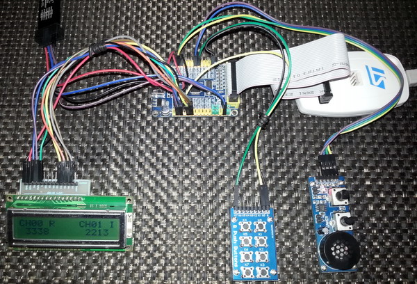
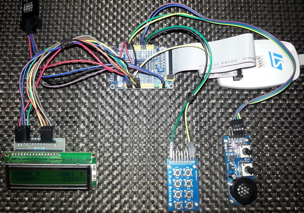
Till now we saw regular and injected groups independently. In this example we’ll see them together. There are two ADC channels. One of them belongs to regular group while the other belongs to injected group. We’ll see that the injected channel will override the conversion of regular channel. Both of these groups are triggered externally. A flashing LED is indicated which conversion is going on. Please check the video for better understanding.
#include "ADC.h"
#include "GPIO.h"
#include "AFIO.h"
#include "Ex_Int.h"
sbit LCD_RS at GPIOB_ODR.B1;
sbit LCD_EN at GPIOB_ODR.B2;
sbit LCD_D4 at GPIOB_ODR.B12;
sbit LCD_D5 at GPIOB_ODR.B13;
sbit LCD_D6 at GPIOB_ODR.B14;
sbit LCD_D7 at GPIOB_ODR.B15;
register unsigned int regular_adc_data = 0;
register unsigned int injected_adc_data = 0;
void setup();
void GPIO_init();
void ADC_init();
void exeternal_interrupt_init();
void lcd_print(unsigned char x_pos, unsigned char y_pos, unsigned int value);
void ADC1_2_ISR()
iv IVT_INT_ADC1_2
ics ICS_AUTO
{
if(ADC1_SRbits.EOC)
{
ADC1_SRbits.EOC = 0;
regular_adc_data = (ADC1_DR & 0x0FFF);
}
if(ADC1_SRbits.JEOC)
{
ADC1_SRbits.JEOC = 0;
injected_adc_data = (ADC1_JDR1 & 0x0FFF);
}
}
void void EXTI11_ISR()
iv IVT_INT_EXTI15_10
ics ICS_AUTO
{
unsigned char s = 0;
if(read_pending_reg(15) != 0)
{
for(s = 0; s < 3; s++)
{
bit_set(GPIOC_ODR, 13);
delay_ms(10);
bit_clr(GPIOC_ODR, 13);
delay_ms(10);
}
pending_clr(15);
}
if(read_pending_reg(11) != 0)
{
for(s = 0; s < 6; s++)
{
bit_set(GPIOC_ODR, 13);
delay_ms(90);
bit_clr(GPIOC_ODR, 13);
delay_ms(90);
}
pending_clr(11);
}
}
void main()
{
setup();
while(1)
{
lcd_print(2, 2, regular_adc_data);
lcd_print(12, 2, injected_adc_data);
};
}
void setup()
{
GPIO_init();
ADC_init();
exeternal_interrupt_init();
LCD_Init();
LCD_Cmd(_LCD_CLEAR);
LCD_Cmd(_LCD_CURSOR_OFF);
lcd_out(1, 1, "CH00 R");
lcd_out(1, 11, "CH01 I");
}
void GPIO_init()
{
enable_GPIOA(enable);
enable_GPIOB(enable);
enable_GPIOC(enable);
pin_configure_low(GPIOA_CRL, 0, (analog_input | input_mode));
pin_configure_low(GPIOA_CRL, 1, (analog_input | input_mode));
pin_configure_high(GPIOB_CRH, 11, (digital_input | input_mode));
pin_configure_high(GPIOC_CRH, 15, (digital_input | input_mode));
pin_configure_high(GPIOC_CRH, 13, (GPIO_PP_output | output_mode_low_speed));
pull_up_enable(GPIOB_ODR, 11);
pull_up_enable(GPIOC_ODR, 15);
}
void ADC_init()
{
ADC1_Enable();
clr_ADC1_settings();
set_ADC_mode(independent_mode);
set_ADC1_data_alignment(right_alignment);
set_ADC1_scan_conversion_mode(disable);
set_ADC1_continuous_conversion_mode(disable);
set_ADC1_sample_time(sample_time_239_5_cycles, 0);
set_ADC1_sample_time(sample_time_239_5_cycles, 1);
set_ADC1_injected_sequence(4, 1);
set_ADC1_injected_number_of_conversions(1);
set_ADC1_external_trigger_injected_conversion_edge(EXTI_15_trigger);
set_ADC1_injected_end_of_conversion_interrupt(enable);
set_ADC1_regular_sequence(1, 1);
set_ADC1_regular_number_of_conversions(1);
set_ADC1_external_trigger_regular_conversion_edge(EXTI_11_trigger);
set_ADC1_regular_end_of_conversion_interrupt(enable);
NVIC_IntEnable(IVT_INT_ADC1_2);
EnableInterrupts();
ADC1_calibrate();
start_ADC1();
}
void exeternal_interrupt_init()
{
AFIO_enable(enable);
falling_edge_selector(11);
falling_edge_selector(15);
set_EXTI8_11(11, PB_pin);
set_EXTI12_15(15, PC_pin);
interrupt_mask(11);
interrupt_mask(15);
NVIC_IntEnable(IVT_INT_EXTI15_10);
}
void lcd_print(unsigned char x_pos, unsigned char y_pos, unsigned int value)
{
unsigned char tmp = 0;
tmp = (value / 1000);
lcd_chr(y_pos, x_pos, (tmp + 48));
tmp = ((value / 100) % 10);
lcd_chr_cp((tmp + 48));
tmp = ((value / 10) % 10);
lcd_chr_cp((tmp + 48));
tmp = (value % 10);
lcd_chr_cp((tmp + 48));
}
 Demo video link: https://www.youtube.com/watch?v=K5XTYtVEoSo.
Common Pitfalls
When dealing with new stuffs, we often make some silly mistakes. In the case of STM32 ADC, the following mistakes are pretty much common:
- ADC not powered.
- ADC not calibrated.
- ADC settings not cleared/reset to defaults.
- Incorrect GPIO port selection and configuration. If a pin is to be set for an analogue input channel then it should be either kept floating or configured as analogue input.
- Wrong mode of operation selected.
- Incorrect peripheral clock selection.
- Same channels configured for different ADCs, for example CH0 configured for ADC1 and 2.
- Different sampling times for two simultaneous channels in dual conversion mode.
- Interrupts not enabled when using them. MikroC’s interrupt assistant feature should be used to avoid such mistakes. The interrupt assistant also help in code generation.
- Improper selection of regular and injected modes.
- Incorrect data alignment. Right alignment should always be used unless needed otherwise.
- Wrong variable type declaration. If the resulting data from a conversion is signed then signed integers should be used.
- Wrong ADC channel sequencing with incorrect channel order.
Final Words
There are many ways to meet a specific measurement case with STM32 ADCs. Imagination is the limit for so. As I stated earlier it is not possible for me to show all ADC operations in this post. Thus I would like readers to try and experiment whatever I showed. If you can take the challenge and if you have understood the basics then I would suggest that you experiment those stuffs which I didn’t cover. Finally there’s a saying
ADC + DMA = Unbeatable Assets
Of course the DMA block is an asset and when there’s an ADC-DMA collaboration, the result is a revolution in measurement. This issue was not regarding DMA and so when I cover the DMA block, I’ll show more about ADC. For now this post is enough to introduce the basics of STM32 ADC.
Happy coding.
Repository: https://github.com/sshahryiar/STM32-Tutorials
Author: Shawon M. Shahryiar
https://www.youtube.com/c/sshahryiar
|
|
Hi,
Simply I need like this: Kindly help me.
For example, I will have 3 adc channels need to be read as per my choice without wasting uC runtime and using interrupt, for example, i have coded here which i typically use in all projects with other uCs,
I need similar thing in STM32 but confused with too many options.
Could you suggest the right way here ?
ISR_intr_vector;
ADR_ISR()
{
static byte channel;
if(channel==0)
{
adcvalue = ADCVALUE from STM;
channel = 1;
}
else if(channel==1)
{
adcvalue = ADCVALUE from STM;
channel = 2;
}
else if(channel==2)
{
adcvalue = ADCVALUE from STM;
channel = 0;
}
channelregofstm32 = channel;
}
Hi,
Thanks for the great post. Do you have a version of your spl library for stm32f407?
thanks
Currently I’m focused towards the STM32F1xx series only…. After completing the tutorials of this series I’ll be going for the STM32F4 series…. Thanks…. 🙂
Great tutorial, thanks for the explanations! Is the DMA post already out? Would be very much appreciated.
Working on it but can’t say when it’ll be published…. Thanks…. 🙂
nice tutorial but you coding looks a bit compiicated for beginners
Thanks…. STM32 or any ARM family is not meant for beginners…. These families of complex micros are intended for high level works and so the learning curve is very steep…. It’s the best I could do rather than making tutorials with magic hexadecimal numbers and funny register names….