STM32 Analogue-to-Digital Converter (ADC)
|
|
Most of us who have experienced 8-bit MCUs previously know how much important it is to have an Analogue-to-Digital Converter (ADC) built-in with a microcontroller. Apart from other hardware extensions unavailable in the early era microcontrollers, many former 8051 microcontroller users shifted primarily to more robust Atmel AVRs and Microchip PICs just for this important peripheral. I don’t feel it necessary to restate the advantages of having such a peripheral embedded in a micro. In traditional 8-bit MCUs aforementioned, the ADC block is somewhat incomplete and users have to work out tricky methods to solve certain problems. The ADC block of STM32 micros is one of the most advanced and sophisticated element to deal with in the entire STM32 arena. There are way too many options for this block in a STM32 micro. In this issue, we will explore this block. 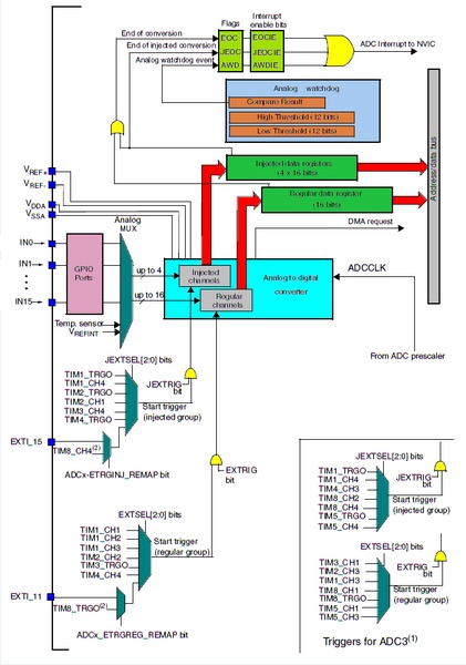
A Simplified Overview of STM32’s ADC Block
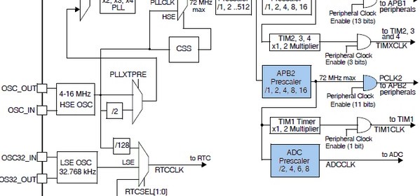
The block diagram shown above might look a bit complex at first but it still worth having a look. It shows us the interfaces that are related to the ADC block and some key features. It seems that some external interrupt pins and internal timer peripherals have some kind of relation with the ADC block. Well these hardware peripherals can trigger ADC conversion. The more we go forward, the more we explore. In short I would like to point out some key features of a typical STM32 ADC:
- 12-bit successive approximation ADC.
- Maximum ADC conversion rate is 1MHz and more than 2MHz in some STM32 families.
- A/D conversion range: 0 – 3.6V DC.
- ADC power supply operating range: 2.4V – 3.6V DC.
- ADC input range: (V_Ref- and V_Ref+ pins are available only in some devices and packages).
- Different modes of operation available for different measurement cases.
- Dual mode conversion on devices with at least 2 ADC units. Some devices have more than 2 ADCs.
- An integrated ADC sequencer ranks channels according to order.
- Channel-by-channel sample time programmability. Having this feature is an advantage because we can set different sampling time for different channels and the ADC block need not to be stopped for making such changes.
- Several external input channels are available. 10 external channels in STM32F103C8T6.
- Two internal ADC channels available with ADC1 (aka. Master ADC). These channels are connected to an internal band gap voltage reference source and an on-chip temperature sensor.
- An Analogue Watchdog (AWD) unit can detect if an ADC channel(s) is operating within a predefined ADC count window.
- DMA-based fast data transferability.
- Several hardware interrupts are available to flag important events.
The Basics of the STM32 ADC Block
The words mode and conversion in STM32 documentations are somewhat ambiguous unless you get them straight. Down to the basics, there are two modes of operation primarily. These are:
- Independent mode. It is just as the typical ADC use. Each ADC unit is operating on its own and without any mutual dependency.
- Dual mode. In this mode two ADCs are converted simultaneously or with some (literally negligible) delay. Two ADC units mutually working together as if they are a single unit.
A/D conversion can be:
- Single Conversion. One sample conversion at a given instant.
- Continuous Conversion. Non-stop sample collection and conversion.
- Discontinuous Conversion. Sequential conversion of some channels in a group.
- Scan Conversion. Sequential sampling and converting of an array of channels one after another.
To start A/D conversion, an ADC unit needs to be stimulated with a trigger signal:
- Software Trigger. A/D conversion as per demand from coded program.
- Hardware Trigger. A/D conversion as per hardware events like external interrupts or timer events.
A/D conversions are done in groups. Group members are ADC channels and need not to be multiple channels. A group may consist of only one channel. Within these groups ADC channels are converted on a scheduled round-robin basis. The good stuff is the fact that unlike most micros we can program which channels belong in a group and with which sequence the A/D conversion is commenced. We can also set the sampling time for each channel separately. ADC groups can be categorized as follows:
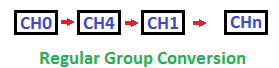
- Regular Group. A given fixed group of ADC channels are regularly converted. Up to 16 channels can be present in a regular group. A regular group is similar to a code running in the main loop.
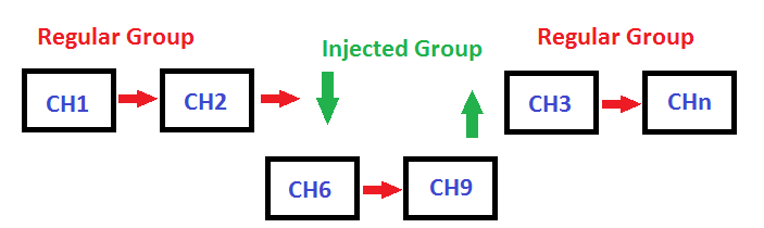
- Injected Group. This group can interrupt a regular group conversion as it has a higher priority over the former. Up to 4 channels can be present in an injected group. When an injected group is present or injected over a regular group, all regular group conversions are halted temporarily. The injected group is processed first and then the regular groups are resumed. An injected group is analogous to having an interrupt over a running code. Alone without a regular group present, an injected group will behave like a regular group.
|
|
Hi,
Simply I need like this: Kindly help me.
For example, I will have 3 adc channels need to be read as per my choice without wasting uC runtime and using interrupt, for example, i have coded here which i typically use in all projects with other uCs,
I need similar thing in STM32 but confused with too many options.
Could you suggest the right way here ?
ISR_intr_vector;
ADR_ISR()
{
static byte channel;
if(channel==0)
{
adcvalue = ADCVALUE from STM;
channel = 1;
}
else if(channel==1)
{
adcvalue = ADCVALUE from STM;
channel = 2;
}
else if(channel==2)
{
adcvalue = ADCVALUE from STM;
channel = 0;
}
channelregofstm32 = channel;
}
Hi,
Thanks for the great post. Do you have a version of your spl library for stm32f407?
thanks
Currently I’m focused towards the STM32F1xx series only…. After completing the tutorials of this series I’ll be going for the STM32F4 series…. Thanks…. 🙂
Great tutorial, thanks for the explanations! Is the DMA post already out? Would be very much appreciated.
Working on it but can’t say when it’ll be published…. Thanks…. 🙂
nice tutorial but you coding looks a bit compiicated for beginners
Thanks…. STM32 or any ARM family is not meant for beginners…. These families of complex micros are intended for high level works and so the learning curve is very steep…. It’s the best I could do rather than making tutorials with magic hexadecimal numbers and funny register names….