STM32 Timers
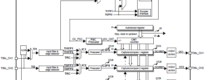
|
|
Time Base Generation
This is most basic use of a timer. In this mode of operation, we will have to program the timer as such that it’ll periodically generate timed events. For this purpose we can use any timer but I recommend using either GP timers or basic timer (if any). There is no specific reason for this recommendation. It is just my way of using STM32 timers – use things that have been designed for their purposes.
For making time base generators we need to follow a few steps and the overall thing is very easy. We will use interrupt-based method. First we need to determine which timer we will be using and what should be the frequency of the timer interrupt. We, then, need to calculate the values for the prescaler (PSC), the auto-reload register (ARR) and the repetition counter (RCR) (if any). Repetition counters are available only in advanced timers only. We can use the following formula for determining interrupt rate:
 RCR will be zero unless used or available and so generally the formula will be:
 TIMx clock is dependent on APB bus clock.
Finally we will be enabling timer interrupts and the counter module itself.
Sometime along its path in the world of embedded systems, MikroElektronika (MikroE), a well-reputed microcontroller-based hardware and software solution provider, developed a free tool called Timer Calculator. This tool made life easy. We can use it to generate codes necessary for timer interrupts. It generate codes for MikroC, MikroBasic or MikroPascal. Originally Timer Calculator used support PIC and AVR platforms only but recently after unveiling MikroE ARM compilers, ARM platforms were incorporated with it. If we have fairly some sound idea of how things are working inside a STM32, we can avoid all the time-consuming, tiring silly calculations and use it to complete your job easily. We just need to select the STM32 family, MCU clock and desired interrupt rate either in terms of time or in terms of frequency. There are also some preset code examples than can also be used to get a head start.
Timer Calculator can be downloaded from here:
http://www.libstock.com/projects/view/398/timer-calculator.
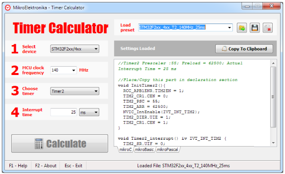
In terms of registers we just need to deal with the following registers only when we need to generate time-bases. I will not explain them in details as their coding will do that.
Code Examples
MikroE Timer Calculator Example
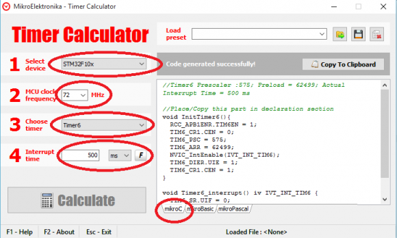
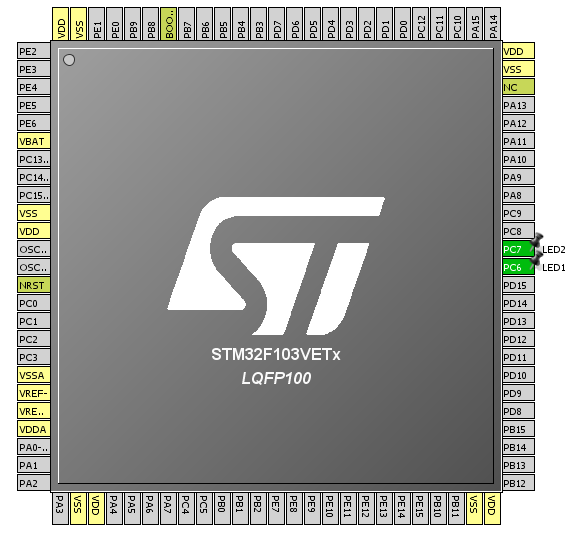
There’s nothing to say about this example as the software says for itself. We just need to the stuffs as marked in the image below. In this example two LEDs connected to GPIOC pin 6 and 7 will toggle logic states every 500ms. Pin C7 LED flashes due to timer 6 update interrupt and pin C6 LED blinks due one main loop execution. After every interrupt, interrupt flags in the timer status registers need to be cleared.
The following setup is used for this code example and the next.
void setup();
void GPIO_init();
void Timer6_init();
void TIM6_ISR()
iv IVT_INT_TIM6
ics ICS_AUTO
{
TIM6_SR.UIF = 0;
GPIOC_ODRbits.ODR7 ^= 1;
}
void main()
{
setup();
while(1)
{
GPIOC_ODRbits.ODR6 ^= 1;
delay_ms(500);
};
}
void setup()
{
GPIO_init();
Timer6_init();
}
void GPIO_init()
{
GPIO_Clk_Enable(&GPIOC_BASE);
GPIO_Config(&GPIOC_BASE,
(_GPIO_PINMASK_6 | _GPIO_PINMASK_7),
(_GPIO_CFG_MODE_OUTPUT | _GPIO_CFG_SPEED_MAX | _GPIO_CFG_OTYPE_PP));
GPIOC_ODRbits.ODR6 = 0;
GPIOC_ODRbits.ODR7 = 0;
}
void Timer6_init()
{
RCC_APB1ENR.TIM6EN = 1;
TIM6_CR1.CEN = 0;
TIM6_PSC = 575;
TIM6_ARR = 62499;
NVIC_IntEnable(IVT_INT_TIM6);
EnableInterrupts();
TIM6_DIER.UIE = 1;
TIM6_CR1.CEN = 1;
}
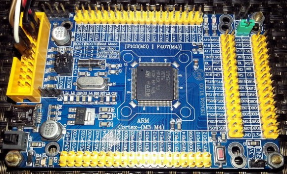
Demo video link: https://www.youtube.com/watch?v=L3TVU7BGK9s.
There are some ignorable limitations of the MikroE Timer Calculator software. For instance it doesn’t support advance timers but I don’t find it as a problem. You can use any other timer like Timer 4 for instance, generated codes for it and then renumber/rename the registers. Another reason for which I’m not bothered by this is due to the fact that advance timers are meant for dedicated advanced tasks and not for silly time-keeping.
|
|


well done sir
How to set the PWM with Center aligned mode ?
Read this app note: http://www.st.com/web/en/resource/technical/document/application_note/DM00042534.pdf
Thanks,
Now need the sample code to change the CMS bits different from ’00’
Great tutorials! Best I’ve found so far.
Thanks…. 🙂
first of all i like to say a million thanks for this tutorial and i have been waiting for this
tutorial i am your biggest fan in stm32 programming for there is little information about it on the web you’ve motivated me to keep having interest in on knowing about the 32bit micros
Thanks…. People like you keeps me going…. 🙂
Pingback: STM32 Timers - Arduino collector blog