STM32 Analogue-to-Digital Converter (ADC)
|
|
Interrupt-Driven Single Channel Continuous Conversion Mode
Many of us may overlook one feature of STM32 micros and that is no other than the presence of an on-chip temperature sensor. All STM32 micros have this sensor. Although it is not recommended for precise temperature measurements, it can be used to estimate PCB or surrounding temperatures around a STM32 micro. The single channel continuous conversion mode is one of the most basic ADC mode. In this mode, once an ADC is triggered a single channel associated with it is continuously converted. In this demo, the single channel is the temperature sensor. The end of conversion interrupt is used to extract ADC conversion result after a conversion finishes. In this way, the CPU is not busy waiting for the ADC to finish conversion. After the end of a conversion, the entire process is repeated and this makes it continuous. From this example onwards you’ll mostly see me incorporating header file from my own SPL with my codes. Take this into account. In the reference manual for STM32F10x series, there’s an entire section dedicated to this temperature sensor. I suggest that you check it out first before trying to understand the code example.
#include "ADC.h"
#include "GPIO.h"
#define V25 1430
#define T_offset 17.5
sbit LCD_RS at GPIOB_ODR.B1;
sbit LCD_EN at GPIOB_ODR.B2;
sbit LCD_D4 at GPIOB_ODR.B12;
sbit LCD_D5 at GPIOB_ODR.B13;
sbit LCD_D6 at GPIOB_ODR.B14;
sbit LCD_D7 at GPIOB_ODR.B15;
register unsigned int adc_data = 0;
const char symbol[8] = {0x00, 0x06, 0x09, 0x09, 0x06, 0x00, 0x00, 0x00};
void setup();
void GPIO_init();
void ADC_init();
void CustomChar(unsigned char y_pos, unsigned char x_pos);
void lcd_print(unsigned char x_pos, unsigned char y_pos, unsigned int value, unsigned char disp_type);
float map(float v, float x_min, float x_max, float y_min, float y_max);
void ADC_ISR()
iv IVT_INT_ADC1_2
ics ICS_AUTO
{
adc_data = (ADC1_DR & 0x0FFF);
bit_set(GPIOC_ODR, 13);
}
void main()
{
register float t = 0.0;
setup();
while(1)
{
t = map(adc_data, 0, 4095, 0, 3300);
t = (((V25 - t) / 4.3) + 25);
t -= T_offset;
t *= 100;
if(t <= 0)
{
t = 0;
}
if(t >= 9999)
{
t = 9999;
}
lcd_print(13, 1, adc_data, 1);
lcd_print(12, 2, t, 0);
bit_clr(GPIOC_ODR, 13);
delay_ms(90);
};
}
void setup()
{
GPIO_init();
ADC_init();
LCD_Init();
LCD_Cmd(_LCD_CLEAR);
LCD_Cmd(_LCD_CURSOR_OFF);
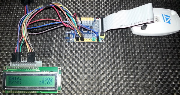
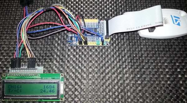
lcd_out(1, 1, "CH16:");
lcd_out(2, 1, "T/ C:");
CustomChar(2, 3);
}
void GPIO_init()
{
enable_GPIOB(enable);
enable_GPIOC(enable);
pin_configure_high(GPIOC_CRH, 13, (GPIO_PP_output | output_mode_low_speed));
}
void ADC_init()
{
ADC1_Enable();
clr_ADC1_settings();
set_ADC_mode(independent_mode);
set_ADC1_data_alignment(right_alignment);
set_ADC1_scan_conversion_mode(disable);
set_ADC1_continuous_conversion_mode(enable);
set_ADC1_external_trigger_regular_conversion_edge(SWSTART_trigger);
set_ADC1_regular_number_of_conversions(1);
set_ADC1_sample_time(sample_time_13_5_cycles, 16);
set_ADC1_regular_sequence(1, 16);
set_ADC1_reference_and_temperature_sensor(enable);
set_ADC1_regular_end_of_conversion_interrupt(enable);
NVIC_IntEnable(IVT_INT_ADC1_2);
EnableInterrupts;
ADC1_calibrate();
start_ADC1();
}
void CustomChar(unsigned char y_pos, unsigned char x_pos)
{
unsigned char i = 0;
Lcd_Cmd(64);
for (i = 0; i < 8; i += 1)
{
Lcd_Chr_CP(symbol[i]);
}
Lcd_Cmd(_LCD_RETURN_HOME);
Lcd_Chr(y_pos, x_pos, 0);
}
void lcd_print(unsigned char x_pos, unsigned char y_pos, unsigned int value, unsigned char disp_type)
{
unsigned char tmp = 0;
tmp = (value / 1000);
lcd_chr(y_pos, x_pos, (tmp + 48));
tmp = ((value / 100) % 10);
lcd_chr_cp((tmp + 48));
switch(disp_type)
{
case 0:
{
lcd_chr_cp(46);
break;
}
case 1:
{
break;
}
}
tmp = ((value / 10) % 10);
lcd_chr_cp((tmp + 48));
tmp = (value % 10);
lcd_chr_cp((tmp + 48));
}
float map(float v, float x_min, float x_max, float y_min, float y_max)
{
return (y_min + (((y_max - y_min)/(x_max - x_min)) * (v - x_min)));
}
 Demo video link: https://www.youtube.com/watch?v=01sV-vgegtk.
Interrupt-Driven Single Channel Single Conversion Mode
STM32 micros have an internal bandgap voltage reference source. The internal voltage reference source is not used by the ADC unlike other micros. It can, however, be used as a comparator input for zero-crossing detection. It may also be possible to use it to calibrate external readings or the V_Ref+ pin. The single channel single conversion mode is another basic ADC mode. In this mode a single channel (the internal reference source as in this example) is converted once when triggered. A single software trigger is used to invoke one ADC conversion. The end of conversion interrupt is used to notify the completion of ADC conversion and then the ADC stops. The only difference between the previous example and this one is how often the ADC conversion is done.
#include "ADC.h"
#include "GPIO.h"
sbit LCD_RS at GPIOB_ODR.B1;
sbit LCD_EN at GPIOB_ODR.B2;
sbit LCD_D4 at GPIOB_ODR.B12;
sbit LCD_D5 at GPIOB_ODR.B13;
sbit LCD_D6 at GPIOB_ODR.B14;
sbit LCD_D7 at GPIOB_ODR.B15;
register unsigned int adc_data = 0;
void setup();
void GPIO_init();
void ADC_init();
void lcd_print(unsigned char x_pos, unsigned char y_pos, unsigned int value);
float map(float v, float x_min, float x_max, float y_min, float y_max);
void ADC_ISR()
iv IVT_INT_ADC1_2
ics ICS_AUTO
{
adc_data = (ADC1_DR & 0x0FFF);
bit_clr(GPIOC_ODR, 13);
}
void main()
{
register float V = 0;
setup();
while(1)
{
set_ADC1_regular_conversions(enable);
bit_set(GPIOC_ODR, 13);
V = map(adc_data, 0, 4095, 0, 3300);
lcd_print(13, 1, adc_data);
lcd_print(13, 2, V);
delay_ms(90);
};
}
void setup()
{
GPIO_init();
ADC_init();
LCD_Init();
LCD_Cmd(_LCD_CLEAR);
LCD_Cmd(_LCD_CURSOR_OFF);
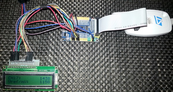
lcd_out(1, 1, "CH17:");
lcd_out(2, 1, "Vref/mV:");
}
void GPIO_init()
{
enable_GPIOB(enable);
enable_GPIOC(enable);
pin_configure_high(GPIOC_CRH, 13, (GPIO_PP_output | output_mode_low_speed));
}
void ADC_init()
{
ADC1_Enable();
clr_ADC1_settings();
set_ADC_mode(independent_mode);
set_ADC1_data_alignment(right_alignment);
set_ADC1_scan_conversion_mode(disable);
set_ADC1_continuous_conversion_mode(disable);
set_ADC1_external_trigger_regular_conversion_edge(SWSTART_trigger);
set_ADC1_regular_number_of_conversions(1);
set_ADC1_sample_time(sample_time_13_5_cycles, 17);
set_ADC1_regular_sequence(1, 17);
set_ADC1_reference_and_temperature_sensor(enable);
set_ADC1_regular_end_of_conversion_interrupt(enable);
NVIC_IntEnable(IVT_INT_ADC1_2);
EnableInterrupts();
ADC1_calibrate();
start_ADC1();
}
void lcd_print(unsigned char x_pos, unsigned char y_pos, unsigned int value)
{
unsigned char tmp = 0;
tmp = (value / 1000);
lcd_chr(y_pos, x_pos, (tmp + 48));
tmp = ((value / 100) % 10);
lcd_chr_cp((tmp + 48));
tmp = ((value / 10) % 10);
lcd_chr_cp((tmp + 48));
tmp = (value % 10);
lcd_chr_cp((tmp + 48));
}
float map(float v, float x_min, float x_max, float y_min, float y_max)
{
return (y_min + (((y_max - y_min)/(x_max - x_min)) * (v - x_min)));
}
 Demo video link: https://www.youtube.com/watch?v=BpiCa0ANWVI.
|
|
Hi,
Simply I need like this: Kindly help me.
For example, I will have 3 adc channels need to be read as per my choice without wasting uC runtime and using interrupt, for example, i have coded here which i typically use in all projects with other uCs,
I need similar thing in STM32 but confused with too many options.
Could you suggest the right way here ?
ISR_intr_vector;
ADR_ISR()
{
static byte channel;
if(channel==0)
{
adcvalue = ADCVALUE from STM;
channel = 1;
}
else if(channel==1)
{
adcvalue = ADCVALUE from STM;
channel = 2;
}
else if(channel==2)
{
adcvalue = ADCVALUE from STM;
channel = 0;
}
channelregofstm32 = channel;
}
Hi,
Thanks for the great post. Do you have a version of your spl library for stm32f407?
thanks
Currently I’m focused towards the STM32F1xx series only…. After completing the tutorials of this series I’ll be going for the STM32F4 series…. Thanks…. 🙂
Great tutorial, thanks for the explanations! Is the DMA post already out? Would be very much appreciated.
Working on it but can’t say when it’ll be published…. Thanks…. 🙂
nice tutorial but you coding looks a bit compiicated for beginners
Thanks…. STM32 or any ARM family is not meant for beginners…. These families of complex micros are intended for high level works and so the learning curve is very steep…. It’s the best I could do rather than making tutorials with magic hexadecimal numbers and funny register names….