STM32 Analogue-to-Digital Converter (ADC)
|
|
Single Injected Channel Continuous Conversion Mode
Previously I stated that injected groups are no different than regular groups when used alone. They will behave like regular groups if regular groups are absent. In this demo there’s no regular group channel and you’ll see that the injected group channel is behaving like a regular group channel.
#include "ADC.h"
#include "GPIO.h"
sbit LCD_RS at GPIOB_ODR.B1;
sbit LCD_EN at GPIOB_ODR.B2;
sbit LCD_D4 at GPIOB_ODR.B12;
sbit LCD_D5 at GPIOB_ODR.B13;
sbit LCD_D6 at GPIOB_ODR.B14;
sbit LCD_D7 at GPIOB_ODR.B15;
void setup();
void GPIO_init();
void ADC_init();
unsigned int read_ADC1();
void lcd_print(unsigned char x_pos, unsigned char y_pos, unsigned int value);
float map(float v, float x_min, float x_max, float y_min, float y_max);
void main()
{
register unsigned int adc_data = 0;
float V = 0.0;
setup();
while(1)
{
bit_set(GPIOC_ODR, 13);
delay_ms(10);
adc_data = read_ADC1();
V = map(adc_data, 0, 4095, 0, 3300);
lcd_print(13, 1, adc_data);
lcd_print(13, 2, V);
bit_clr(GPIOC_ODR, 13);
delay_ms(90);
};
}
void setup()
{
GPIO_init();
ADC_init();
LCD_Init();
LCD_Cmd(_LCD_CLEAR);
LCD_Cmd(_LCD_CURSOR_OFF);
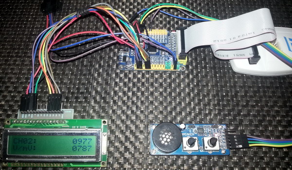
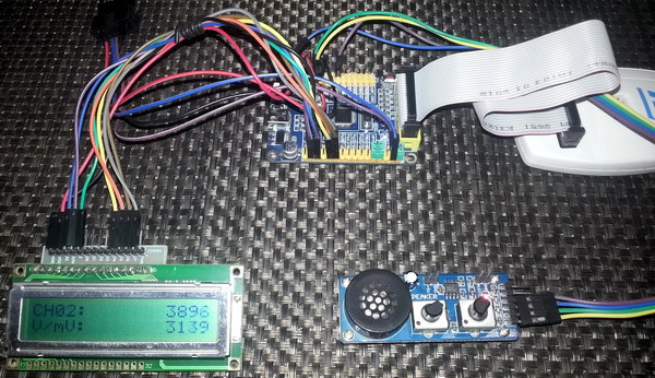
lcd_out(1, 1, "CH03:");
lcd_out(2, 1, "V/mV:");
}
void GPIO_init()
{
enable_GPIOA(enable);
enable_GPIOB(enable);
enable_GPIOC(enable);
pin_configure_low(GPIOA_CRL, 3, (analog_input | input_mode));
pin_configure_high(GPIOC_CRH, 13, (GPIO_PP_output | output_mode_low_speed));
}
void ADC_init()
{
ADC1_Enable();
clr_ADC1_settings();
set_ADC_mode(independent_mode);
set_ADC1_data_alignment(right_alignment);
set_ADC1_scan_conversion_mode(disable);
set_ADC1_continuous_conversion_mode(enable);
set_ADC1_injected_number_of_conversions(1);
set_ADC1_sample_time(sample_time_239_5_cycles, 3);
set_ADC1_injected_sequence(4, 3);
set_ADC1_external_trigger_injected_conversion_edge(JSWSTART_trigger);
ADC1_calibrate();
start_ADC1();
}
unsigned int read_ADC1()
{
set_ADC1_injected_conversions(enable);
while(ADC1_SRbits.JEOC == 0);
return (ADC1_JDR1 & 0x0FFF);
}
void lcd_print(unsigned char x_pos, unsigned char y_pos, unsigned int value)
{
unsigned char tmp = 0;
tmp = (value / 1000);
lcd_chr(y_pos, x_pos, (tmp + 48));
tmp = ((value / 100) % 10);
lcd_chr_cp((tmp + 48));
tmp = ((value / 10) % 10);
lcd_chr_cp((tmp + 48));
tmp = (value % 10);
lcd_chr_cp((tmp + 48));
}
float map(float v, float x_min, float x_max, float y_min, float y_max)
{
return (y_min + (((y_max - y_min)/(x_max - x_min)) * (v - x_min)));
}
 Demo video link: https://www.youtube.com/watch?v=R1MuJaWrfn8.
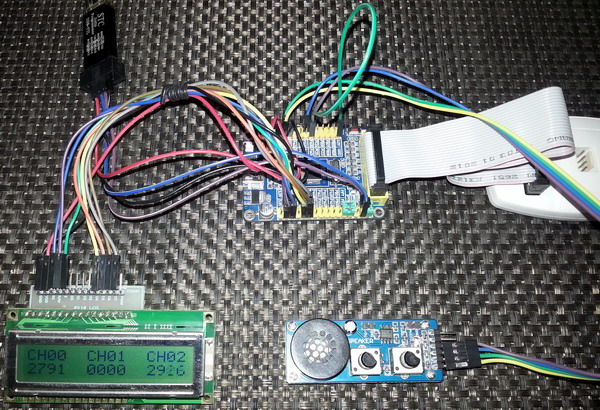
Multiple Injected Channels in Discontinuous Conversion Mode
In discontinuous mode, each injected group channel is converted according to a sequence and after each channel conversion an injected channel end of conversion flag is set. Since there can be four channels in an injected group, their conversion results are stored in four separate data registers. We just need to read those data registers when valid data values are ready. To use discontinuous mode we must specify the number of channels in the discontinuous mode apart from how many channels that are actually present in the group.
#include "ADC.h"
#include "GPIO.h"
sbit LCD_RS at GPIOB_ODR.B1;
sbit LCD_EN at GPIOB_ODR.B2;
sbit LCD_D4 at GPIOB_ODR.B12;
sbit LCD_D5 at GPIOB_ODR.B13;
sbit LCD_D6 at GPIOB_ODR.B14;
sbit LCD_D7 at GPIOB_ODR.B15;
void setup();
void GPIO_init();
void ADC_init();
void read_ADC1_injected(unsigned int temp_data[3]);
void lcd_print(unsigned char x_pos, unsigned char y_pos, unsigned int value);
void main()
{
unsigned int channel_data[3];
setup();
while(1)
{
read_ADC1_injected(channel_data);
lcd_print(1, 2, channel_data[0]);
lcd_print(7, 2, channel_data[1]);
lcd_print(13, 2, channel_data[2]);
bit_set(GPIOC_ODR, 13);
delay_ms(10);
bit_clr(GPIOC_ODR, 13);
delay_ms(90);
};
}
void setup()
{
GPIO_init();
ADC_init();
LCD_Init();
LCD_Cmd(_LCD_CLEAR);
LCD_Cmd(_LCD_CURSOR_OFF);
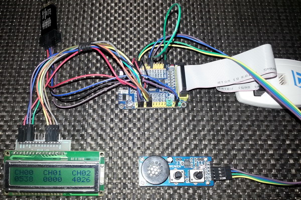
lcd_out(1, 1, "CH00 CH01 CH02");
}
void GPIO_init()
{
enable_GPIOA(enable);
enable_GPIOB(enable);
enable_GPIOC(enable);
pin_configure_low(GPIOA_CRL, 0, (analog_input | input_mode));
pin_configure_low(GPIOA_CRL, 1, (analog_input | input_mode));
pin_configure_low(GPIOA_CRL, 2, (analog_input | input_mode));
pin_configure_high(GPIOC_CRH, 13, (GPIO_PP_output | output_mode_low_speed));
}
void ADC_init()
{
ADC1_Enable();
clr_ADC1_settings();
set_ADC_mode(independent_mode);
set_ADC1_data_alignment(right_alignment);
set_ADC1_scan_conversion_mode(disable);
set_ADC1_continuous_conversion_mode(disable);
set_ADC1_injected_number_of_conversions(3);
set_ADC1_sample_time(sample_time_28_5_cycles, 0);
set_ADC1_sample_time(sample_time_41_5_cycles, 1);
set_ADC1_sample_time(sample_time_13_5_cycles, 2);
set_ADC1_injected_sequence(1, 0);
set_ADC1_injected_sequence(2, 2);
set_ADC1_injected_sequence(3, 1);
set_ADC1_number_of_discontinuous_conversions(3);
set_ADC1_external_trigger_injected_conversion_edge(JSWSTART_trigger);
set_ADC1_discontinuous_conversion_mode_in_injected_mode(enable);
ADC1_calibrate();
start_ADC1();
}
void read_ADC1_injected(unsigned int temp_data[3])
{
set_ADC1_injected_conversions(enable);
while(ADC1_SRbits.JEOC == 0);
temp_data[0] = (ADC1_JDR3 & 0x0FFF);
set_ADC1_injected_conversions(enable);
while(ADC1_SRbits.JEOC == 0);
temp_data[1] = (ADC1_JDR2 & 0x0FFF);
set_ADC1_injected_conversions(enable);
while(ADC1_SRbits.JEOC == 0);
temp_data[2] = (ADC1_JDR1 & 0x0FFF);
}
void lcd_print(unsigned char x_pos, unsigned char y_pos, unsigned int value)
{
unsigned char tmp = 0;
tmp = (value / 1000);
lcd_chr(y_pos, x_pos, (tmp + 48));
tmp = ((value / 100) % 10);
lcd_chr_cp((tmp + 48));
tmp = ((value / 10) % 10);
lcd_chr_cp((tmp + 48));
tmp = (value % 10);
lcd_chr_cp((tmp + 48));
}
 Demo video link: https://www.youtube.com/watch?v=YwymJs8LlNU.
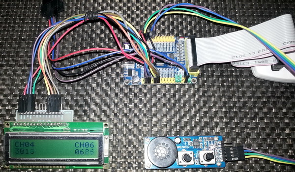
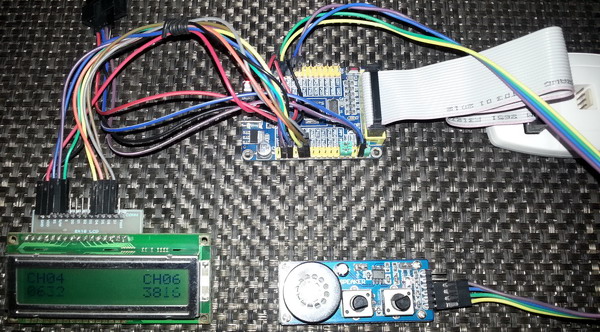
Multiple Injected Channels in Scan Conversion Mode
Scan mode is another interesting mode. In scan mode all ADC channels are scanned as per sequence. One conversion is performed for each channel. After having completed a scan an injected channel end of conversion flag is set. If interrupt is used then an end of conversion interrupt is issued. Scan mode is useful when we need to monitor several ADC channels, for example temperature and relative humidity. There’s a word of caution for using scan mode. STM32 reference manual states it like this:
Unlike a regular conversion sequence, if JL[1:0] length is less than four, the channels are converted in a sequence starting from (4-JL). Example: ADC_JSQR[21:0] = 10 00011 00011 00111 00010 means that a scan conversion will convert the following channel sequence: 7, 3, 3. (not 2, 7, 3)This is why you’ll see some anomalies in this code example:
set_ADC2_injected_sequence(3, 4);
set_ADC2_injected_sequence(4, 6);
void ADC1_2_ISR()
iv IVT_INT_ADC1_2
ics ICS_AUTO
{
ADC2_SRbits.JEOC = 0;
channel_data[0] = (ADC2_JDR1 & 0x0FFF);
channel_data[1] = (ADC2_JDR2 & 0x0FFF);
}
Notice the sequence order and how the data is actually extracted. Keep this in mind while coding for injected groups in scan mode. Also note that in this code I used ADC2 instead of ADC1. This is not mandatory. I did so just to show that you can also use ADC2 rather than ADC1. For regular group channels the scan mode is DMA dependent because for regular group channels there’s only one data register for all the regular channels. I didn’t find a good way to avoid using the DMA unit. Of course using DMA is a much more clever approach. Since I won’t be discussing about DMA in this issue, I’m skipping this part for future.
#include "ADC.h"
#include "GPIO.h"
sbit LCD_RS at GPIOB_ODR.B1;
sbit LCD_EN at GPIOB_ODR.B2;
sbit LCD_D4 at GPIOB_ODR.B12;
sbit LCD_D5 at GPIOB_ODR.B13;
sbit LCD_D6 at GPIOB_ODR.B14;
sbit LCD_D7 at GPIOB_ODR.B15;
unsigned int channel_data[2];
void setup();
void GPIO_init();
void ADC_init();
void lcd_print(unsigned char x_pos, unsigned char y_pos, unsigned int value);
void ADC1_2_ISR()
iv IVT_INT_ADC1_2
ics ICS_AUTO
{
ADC2_SRbits.JEOC = 0;
channel_data[0] = (ADC2_JDR1 & 0x0FFF);
channel_data[1] = (ADC2_JDR2 & 0x0FFF);
}
void main()
{
setup();
while(1)
{
bit_set(GPIOC_ODR, 13);
set_ADC2_injected_conversions(enable);
delay_ms(10);
lcd_print(1, 2, channel_data[0]);
lcd_print(13, 2, channel_data[1]);
bit_clr(GPIOC_ODR, 13);
delay_ms(90);
};
}
void setup()
{
GPIO_init();
LCD_Init();
ADC_init();
LCD_Cmd(_LCD_CLEAR);
LCD_Cmd(_LCD_CURSOR_OFF);
lcd_out(1, 1, "CH04 CH06");
}
void GPIO_init()
{
enable_GPIOA(enable);
enable_GPIOB(enable);
enable_GPIOC(enable);
pin_configure_low(GPIOA_CRL, 4, (analog_input | input_mode));
pin_configure_low(GPIOA_CRL, 6, (analog_input | input_mode));
pin_configure_high(GPIOC_CRH, 13, (GPIO_PP_output | output_mode_low_speed));
}
void ADC_init()
{
ADC2_Enable();
clr_ADC2_settings();
set_ADC_mode(independent_mode);
set_ADC2_data_alignment(right_alignment);
set_ADC2_scan_conversion_mode(enable);
set_ADC2_continuous_conversion_mode(disable);
set_ADC2_sample_time(sample_time_1_5_cycles, 4);
set_ADC2_sample_time(sample_time_13_5_cycles, 6);
set_ADC2_external_trigger_injected_conversion_edge(JSWSTART_trigger);
set_ADC2_injected_number_of_conversions(2);
set_ADC2_injected_sequence(3, 4);
set_ADC2_injected_sequence(4, 6);
set_ADC2_injected_end_of_conversion_interrupt(enable);
NVIC_IntEnable(IVT_INT_ADC1_2);
EnableInterrupts();
ADC2_calibrate();
start_ADC2();
}
void lcd_print(unsigned char x_pos, unsigned char y_pos, unsigned int value)
{
unsigned char tmp = 0;
tmp = (value / 1000);
lcd_chr(y_pos, x_pos, (tmp + 48));
tmp = ((value / 100) % 10);
lcd_chr_cp((tmp + 48));
tmp = ((value / 10) % 10);
lcd_chr_cp((tmp + 48));
tmp = (value % 10);
lcd_chr_cp((tmp + 48));
}
 Demo video link: https://www.youtube.com/watch?v=Mjax8dwClGE.
|
|
Hi,
Simply I need like this: Kindly help me.
For example, I will have 3 adc channels need to be read as per my choice without wasting uC runtime and using interrupt, for example, i have coded here which i typically use in all projects with other uCs,
I need similar thing in STM32 but confused with too many options.
Could you suggest the right way here ?
ISR_intr_vector;
ADR_ISR()
{
static byte channel;
if(channel==0)
{
adcvalue = ADCVALUE from STM;
channel = 1;
}
else if(channel==1)
{
adcvalue = ADCVALUE from STM;
channel = 2;
}
else if(channel==2)
{
adcvalue = ADCVALUE from STM;
channel = 0;
}
channelregofstm32 = channel;
}
Hi,
Thanks for the great post. Do you have a version of your spl library for stm32f407?
thanks
Currently I’m focused towards the STM32F1xx series only…. After completing the tutorials of this series I’ll be going for the STM32F4 series…. Thanks…. 🙂
Great tutorial, thanks for the explanations! Is the DMA post already out? Would be very much appreciated.
Working on it but can’t say when it’ll be published…. Thanks…. 🙂
nice tutorial but you coding looks a bit compiicated for beginners
Thanks…. STM32 or any ARM family is not meant for beginners…. These families of complex micros are intended for high level works and so the learning curve is very steep…. It’s the best I could do rather than making tutorials with magic hexadecimal numbers and funny register names….