STM32 Analogue-to-Digital Converter (ADC)
|
|
Regular Group Channels Discontinuous in Mode
This example is similar to the one I coded for injected group channels. It is somewhat an alternative of scan mode for regular group though technically they are not same. You can use this mode to monitor several ADC channels in a systematic order.
#include "ADC.h"
#include "GPIO.h"
sbit LCD_RS at GPIOB_ODR.B1;
sbit LCD_EN at GPIOB_ODR.B2;
sbit LCD_D4 at GPIOB_ODR.B12;
sbit LCD_D5 at GPIOB_ODR.B13;
sbit LCD_D6 at GPIOB_ODR.B14;
sbit LCD_D7 at GPIOB_ODR.B15;
unsigned char channel_no = 0;
unsigned int ch_data[3] = {0x0000, 0x0000, 0x0000};
void setup();
void GPIO_init();
void ADC_init();
void lcd_print(unsigned char x_pos, unsigned char y_pos, unsigned int value);
void ADC1_2_ISR()
iv IVT_INT_ADC1_2
ics ICS_AUTO
{
ADC2_SRbits.EOC = 0;
ch_data[channel_no] = (ADC2_DR & 0x0FFF);
channel_no++;
}
void main()
{
unsigned char s = 0;
setup();
while(1)
{
bit_set(GPIOC_ODR, 13);
set_ADC2_regular_conversions(enable);
while(channel_no < 3);
channel_no = 0;
for(s = 0 ; s < 3; s++)
{
lcd_print(((s * 6) + 1), 2, ch_data[s]);
}
bit_clr(GPIOC_ODR, 13);
};
}
void setup()
{
GPIO_init();
ADC_init();
LCD_Init();
LCD_Cmd(_LCD_CLEAR);
LCD_Cmd(_LCD_CURSOR_OFF);
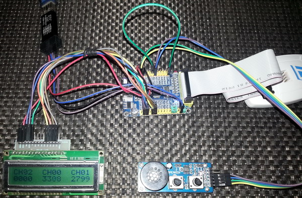
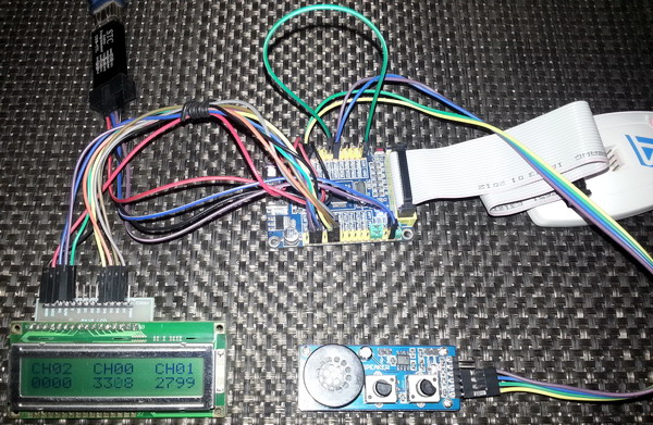
lcd_out(1, 1, "CH02 CH00 CH01");
}
void GPIO_init()
{
enable_GPIOA(enable);
enable_GPIOB(enable);
enable_GPIOC(enable);
pin_configure_low(GPIOA_CRL, 0, (analog_input | input_mode));
pin_configure_low(GPIOA_CRL, 1, (analog_input | input_mode));
pin_configure_low(GPIOA_CRL, 2, (analog_input | input_mode));
pin_configure_high(GPIOC_CRH, 13, (GPIO_PP_output | output_mode_low_speed));
}
void ADC_init()
{
ADC2_Enable();
clr_ADC2_settings();
set_ADC_mode(independent_mode);
set_ADC2_data_alignment(right_alignment);
set_ADC2_scan_conversion_mode(disable);
set_ADC2_continuous_conversion_mode(disable);
set_ADC2_regular_number_of_conversions(3);
set_ADC2_number_of_discontinuous_conversions(3);
set_ADC2_sample_time(sample_time_41_5_cycles, 0);
set_ADC2_sample_time(sample_time_13_5_cycles, 1);
set_ADC2_sample_time(sample_time_28_5_cycles, 2);
set_ADC2_regular_sequence(1, 0);
set_ADC2_regular_sequence(2, 1);
set_ADC2_regular_sequence(3, 2);
set_ADC2_external_trigger_regular_conversion_edge(SWSTART_trigger);
set_ADC2_discontinuous_conversion_mode_in_regular_mode(enable);
set_ADC2_regular_end_of_conversion_interrupt(enable);
NVIC_IntEnable(IVT_INT_ADC1_2);
EnableInterrupts();
ADC2_calibrate();
start_ADC2();
}
void lcd_print(unsigned char x_pos, unsigned char y_pos, unsigned int value)
{
unsigned char tmp = 0;
tmp = (value / 1000);
lcd_chr(y_pos, x_pos, (tmp + 48));
tmp = ((value / 100) % 10);
lcd_chr_cp((tmp + 48));
tmp = ((value / 10) % 10);
lcd_chr_cp((tmp + 48));
tmp = (value % 10);
lcd_chr_cp((tmp + 48));
}
 Demo video link: https://www.youtube.com/watch?v=pz-y_W2Lxr8.
Dual Conversion Mode
One of the cool feature of STM32’s ADC is its ability to simultaneous convert two ADC channels. This ability is sometimes highly demanded in some applications. For example in an energy meter you’ll need to measure both voltage and current simultaneous if you want precision. Applications like such demand the use of dual ADC mode. Please note that this feature is available only in those STM32 micros that have at least two ADC units. Fortunately there are only a few STM32 micros that have only one ADC unit. ST provided several sub modes for dual ADC modes but none attracted me much because those seemed to my achievable using one ADC and some programming tricks. It’s just my instinct. I could be wrong. To use dual ADC mode, we need to configure two ADC units separately. They’ll have some common setups. The individual ADCs are configured as such that as if they are configured for single ADC operation. The common settings are just ADC mode of operation setting and interrupt configuration. The results of ADC conversions of both channels are stored in ADC1_DR register Please note that ST recommends that we set the DMA bit for ADC1 even if we don’t use the DMA block itself.
#include "ADC.h"
#include "GPIO.h"
sbit LCD_RS at GPIOB_ODR.B1;
sbit LCD_EN at GPIOB_ODR.B2;
sbit LCD_D4 at GPIOB_ODR.B12;
sbit LCD_D5 at GPIOB_ODR.B13;
sbit LCD_D6 at GPIOB_ODR.B14;
sbit LCD_D7 at GPIOB_ODR.B15;
register unsigned long adc_data = 0;
void setup();
void GPIO_init();
void ADC_init();
void setup_ADC1();
void setup_ADC2();
void setup_common_ADC_settings();
void lcd_print(unsigned char x_pos, unsigned char y_pos, unsigned int value);
void ADC1_2_ISR()
iv IVT_INT_ADC1_2
ics ICS_AUTO
{
ADC1_SRbits.EOC = 0;
ADC2_SRbits.EOC = 0;
adc_data = adc1_dr;
bit_set(GPIOC_ODR, 13);
}
void main()
{
unsigned int adc1_data = 0;
unsigned int adc2_data = 0;
setup();
while(1)
{
set_ADC1_regular_conversions(enable);
adc1_data = (adc_data & 0x00000FFF);
adc2_data = ((adc_data & 0x0FFF0000) >> 16);
lcd_print(1, 2, adc1_data);
lcd_print(13, 2, adc2_data);
bit_clr(GPIOC_ODR, 13);
delay_ms(90);
};
}
void setup()
{
GPIO_init();
ADC_init();
LCD_Init();
LCD_Cmd(_LCD_CLEAR);
LCD_Cmd(_LCD_CURSOR_OFF);
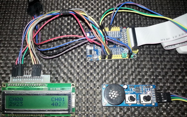
lcd_out(1, 1, "CH00 CH01");
}
void GPIO_init()
{
enable_GPIOA(enable);
enable_GPIOB(enable);
enable_GPIOC(enable);
pin_configure_low(GPIOA_CRL, 0, (analog_input | input_mode));
pin_configure_low(GPIOA_CRL, 1, (analog_input | input_mode));
pin_configure_high(GPIOC_CRH, 13, (GPIO_PP_output | output_mode_low_speed));
}
void ADC_init()
{
setup_ADC1();
setup_ADC2();
setup_common_ADC_settings();
}
void setup_ADC1()
{
ADC1_Enable();
clr_ADC1_settings();
set_ADC1_data_alignment(right_alignment);
set_ADC1_scan_conversion_mode(disable);
set_ADC1_continuous_conversion_mode(disable);
set_ADC1_sample_time(sample_time_41_5_cycles, 0);
set_ADC1_external_trigger_regular_conversion_edge(SWSTART_trigger);
set_ADC1_regular_number_of_conversions(1);
set_ADC1_regular_sequence(1, 0);
set_ADC1_regular_end_of_conversion_interrupt(enable);
ADC1_calibrate();
start_ADC1();
}
void setup_ADC2()
{
ADC2_Enable();
clr_ADC2_settings();
set_ADC2_data_alignment(right_alignment);
set_ADC2_scan_conversion_mode(disable);
set_ADC2_continuous_conversion_mode(disable);
set_ADC2_sample_time(sample_time_41_5_cycles, 1);
set_ADC2_external_trigger_regular_conversion_edge(SWSTART_trigger);
set_ADC2_regular_number_of_conversions(1);
set_ADC2_regular_sequence(1, 1);
set_ADC2_regular_end_of_conversion_interrupt(enable);
ADC2_calibrate();
start_ADC2();
}
void setup_common_ADC_settings()
{
set_ADC1_DMA(enable);
set_ADC_mode(regular_simultaneous_mode_only);
NVIC_IntEnable(IVT_INT_ADC1_2);
EnableInterrupts();
}
void lcd_print(unsigned char x_pos, unsigned char y_pos, unsigned int value)
{
unsigned char tmp = 0;
tmp = (value / 1000);
lcd_chr(y_pos, x_pos, (tmp + 48));
tmp = ((value / 100) % 10);
lcd_chr_cp((tmp + 48));
tmp = ((value / 10) % 10);
lcd_chr_cp((tmp + 48));
tmp = (value % 10);
lcd_chr_cp((tmp + 48));
}
 Demo video link: https://www.youtube.com/watch?v=sSGJUkX-mSg.
|
|
Hi,
Simply I need like this: Kindly help me.
For example, I will have 3 adc channels need to be read as per my choice without wasting uC runtime and using interrupt, for example, i have coded here which i typically use in all projects with other uCs,
I need similar thing in STM32 but confused with too many options.
Could you suggest the right way here ?
ISR_intr_vector;
ADR_ISR()
{
static byte channel;
if(channel==0)
{
adcvalue = ADCVALUE from STM;
channel = 1;
}
else if(channel==1)
{
adcvalue = ADCVALUE from STM;
channel = 2;
}
else if(channel==2)
{
adcvalue = ADCVALUE from STM;
channel = 0;
}
channelregofstm32 = channel;
}
Hi,
Thanks for the great post. Do you have a version of your spl library for stm32f407?
thanks
Currently I’m focused towards the STM32F1xx series only…. After completing the tutorials of this series I’ll be going for the STM32F4 series…. Thanks…. 🙂
Great tutorial, thanks for the explanations! Is the DMA post already out? Would be very much appreciated.
Working on it but can’t say when it’ll be published…. Thanks…. 🙂
nice tutorial but you coding looks a bit compiicated for beginners
Thanks…. STM32 or any ARM family is not meant for beginners…. These families of complex micros are intended for high level works and so the learning curve is very steep…. It’s the best I could do rather than making tutorials with magic hexadecimal numbers and funny register names….