Author Archives: Shawon Shahryiar

XMega Analog Comparator
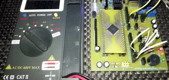
Previously we dealt with the XMega Analog-to-Digital Converter (ADC) block. We know that we can use the ADC to measure voltages and take decisions based on voltage values/levels but sometimes it is enough to detect voltage levels and not to measure the exact voltage values. In such occasions where we just need to check voltage levels relative to a reference or threshold value, we need an Analog Comparator (AC). An analog comparator can be used to compare two voltage levels and based on that it can be used to generate a logic output (0 or 1) to indicate which of the two levels is higher or lower than the other. That’s all and there isn’t much about analog comparators. The XMega family of micros come loaded with high performance dual analog comparator modules. However so far we saw that between the traditional 8-bit micros and the XMega micros, the major difference apart from programming is the overall nifty enhancements in all common hardware blocks. When it comes to the analog comparators of the XMega micros, the same is true. In this issue we will explore the XMega analog comparator block.
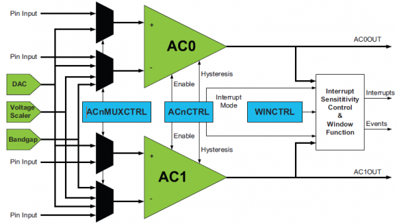
Block Diagram


Read more

STM32 Timers

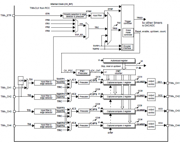
Everything related to digital electronics is related to time. Timer, counter, frequency, pulse width, clock and time are the most common words one may find in this arena. Microcontrollers just like humans need heart-beats and these come from clock sources. Apart from system clock, timers are clock sources that can be used as heart-beats for various applications. All modern micros are embedded with timer-counter modules and generally they are used for generating time bases, counting pulses, measuring time periods of waveforms, generating pulse width modulation (PWM) signals, triggering external devices and timing special events. STM32 micros have several timers designed for such applications. However unlike most 8-bit micros which possess two/three timers with limited functionalities, the timers of STM32s are very elaborate and complex. This explains why documentations related to timer modules take about 25% of any STM32 reference manual.

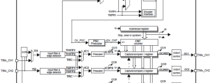
Block Diagram

Before we begin exploring STM32 timers, I must point out that I won’t be able to cover every aspect of all timer modules as they are vast and need lot of explanations, something which is beyond the scope of a single post. This is why in this issue we shall explore the very basics of timer modules enough to get STM32 timers to work.

Read more

XMega ADC

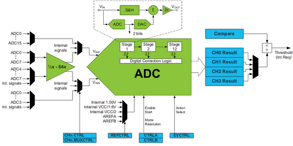
For users of advance MCUs like the XMega it is not necessary to tell what an analog-to-digital converter (ADC) is or what it does. I assume this is not the first family of microcontroller they are dealing with. Unlike the ADCs of other microcontroller the ADC of XMega devices is a highly complex tool. The level of complexity is so much that without understanding every bits-and-pieces of this piece of hardware a user won’t enjoy its absolute power. XMega ADC is also the most confusing hardware as it is not like other MCU ADCs. We will be dealing with ATXMega32A4U and it has only one ADC block, named ADCA but some other XMega devices like the XMega128A1 have more than one ADC block – ADCA and ADCB. By the way the XMega reference manual provides a long literature on the ADC and I’m not willing to state everything.

A quick view of the ADC block diagram shows most of the internal arrangement.

ADC internal

Read more

XMega Clock System

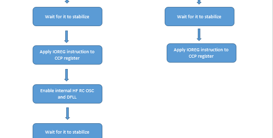
Okay firstly the reason I wrote about the clock system instead of I/O ports or something else in this second post of the XMega series is simply because of the fact that without understanding clock configurations you won’t get what you want from your chip. Since XMega’s clock system is software-level configurable and complex at first, it makes itself the first priority module before anything else.

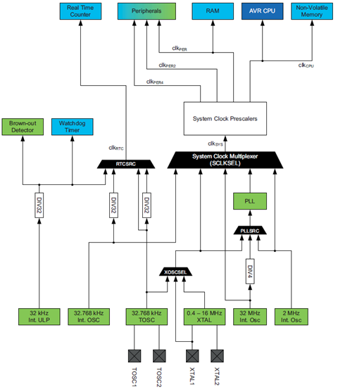
There are several clock sources that XMega micros can use as clock. These are both internal and external clock sources. As stated earlier, clocks are not set by fuse settings unlike traditional Mega AVRs, they are controlled by software and the outputs from these sources can be multiplied using the internal Phase Locked-Loop (PLL). Thus there’s a wide range of clocks available in the XMega and it’ll not be needed to shut down and reprogram the XMega just to change its clock – a great relief from meddling with fuse settings. Some port pins can also output the system clock frequency. Literally there’s no need to depend on external quartz crystals which are not available in all frequencies.

XMega Clock System Internal
Read more

STM32 GPIO Ports Insights

In any microcontroller there is at least one general purpose input-output port. STM32 is a not different breed and as expected it also has several GPIO ports. These ports are usually named GPIOA, GPIOB, etc. but unlike most 8/16-bit micros these ports are 16 bit wide. Thus, in general, every port has 16 IO pins. Port pins have several modes of operation and this is what that makes them both robust and complex at first. In development boards the IO port pin naming is cut short and so we’ll find PA0, PB12, etc. instead of GPIOA0, GPIOB12, etc. Even in the reference manuals this short naming is used widely. In the end every I/O pin is general purpose in nature.

Key points with STM32’s GPIO

  • Upon any reset event all GPIOs are floating inputs. This prevents any accidental damage to GPIOs in the event of emergency.
  • All GPIO registers are needed to be accessed with 32 bit words. This is mandatory.
  • Reserved bits for any GPIO register are kept at reset values i.e. 0.
  • For every GPIO port there are seven registers but the only the first four are the most important ones. The rest can be ignored most of the times.
  • These important GPIO registers per port are CRL, CRH, IDR and ODR. The rest three registers for GPIO ports can be avoided at the beginning.
  • For bit set and for bit clear, operations REGx |= (1 << bit) and REGx &= ~ (1 << bit) respectively are very handy and efficient. However MikroC compiler provides bit level access though its internal header file coding like this GPIOB_BSRRbits.BS15. We can use this method or the other one.
  • Some IOs are 5V tolerant and are label “FT” in datasheets and other docs. The rest of the I/O pins are not that tolerant and so 3.3V operation should always be ensured. STM32 has a maximum VDD tolerance of 4V but this value shouldn’t be used in any situation for safe operation. Best is to avoid 5V use with GPIOs whenever possible. This will help in avoiding accidental damage to the micro due to common mistakes.
  • Unused GPIO pins should be kept at reset state or tied to ground with 10kΩ resistors so that they remain either as floating inputs or safely connected to ground though it’s not a must.
  • I/O pins can source or sink currents up to 25mA. Thus direct LED drive is possible with them. To drive loads that need more than this value, we must use external BJTs, MOSFETs, optocouplers, transistor arrays or other driver devices.
  • I/O pins should not directly drive inductive or capacitive loads.
  • Care should be taken to avoid driving outputs beyond 50MHz. This is the maximum I/O pin frequency rating.
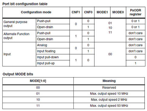
  • CRL/H registers essential set GPIO pin operating mode independently as according to the table below:

Port Configurations

  • CRL sets GPIOs from 0 – 7 while CRH sets from 8 – 15. All IO ports are 16 bit wide unlike common 8 bit micros like PIC or AVR.

Read more

« Older Entries Recent Entries »