Starting STM8 Microcontrollers
|
|
External Interrupt (EXTI)
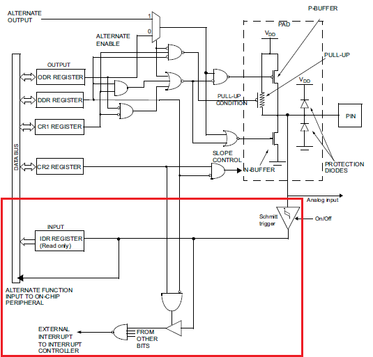
External interrupt is an additional feature of GPIOs in input mode. It makes a micro to respond instantly to changes done on it GPIO input pin(s) by an external events/triggers, skipping other tasks. External interrupts are useful in many scenarios. For instance, an emergency button. Consider the case of a treadmill. You are running at a speed and suddenly you get an ache in one of your ankles. You’ll surely want to stop running immediately. Rather decreasing speed in small steps, you can hit the emergency button to quickly stop the treadmill. The emergency button will interrupt all other processes and immediately instruct the treadmill’s CPU to decrease speed faster than otherwise possible. Thus, it has high priority over other processes.
In most 8-bit micros, there are few external interrupt pins and very limited options are available for them but that’s not the case with STM’s micros. In STM8s, almost all GPIO pins have independent external interrupt capability with input Schmitt triggers. Additionally, there’s interrupt controller to set interrupt priority.
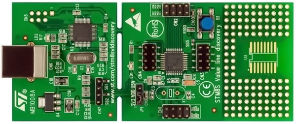
Hardware Connection
Code Example
We will do the same variable flash rate LED blinking example as in the GPIO example but this time with the DISCO board’s button in external interrupt mode. The code here needs special attention as now we will see how interrupts are configured and coded. This code is way different than anything I saw before. I’m saying so because you’ll need to follow certain steps unlike other compilers. In other compilers, all we do is create the interrupt function and tell the compiler the interrupt vector address. Same here too but too many steps involved.
Now check the interrupt vector table of STM8S003 below:

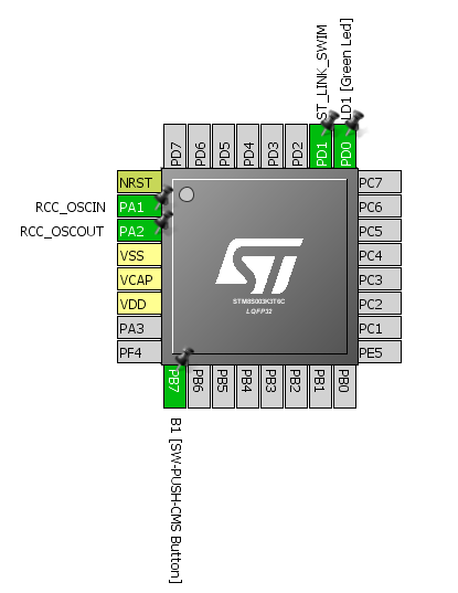
You’ll find this table not in the reference manual but in the device’s datasheet. This table varies with devices and so be sure of correct datasheet. The DISCO board’s button is connected to PB7 and so clearly, we will need IRQ4, i.e. EXTI1 or PORTB external interrupts. All external interrupts on GPIOB pin are masked in this vector address.
Please note that codes that use peripheral interrupts need stm8s_it.h and stm8s_it.c files. Therefore, add them if you are to use interrupts.
main.c
#include "stm8s.h"
bool state = FALSE;
void GPIO_setup(void);
void EXTI_setup(void);
void clock_setup(void);
void main(void)
{
GPIO_setup();
EXTI_setup();
clock_setup();
do
{
GPIO_WriteReverse(GPIOD, GPIO_PIN_0);
if(state == TRUE)
{
delay_ms(100);
}
else
{
delay_ms(1000);
}
}while (TRUE);
}
void GPIO_setup(void)
{
GPIO_DeInit(GPIOB);
GPIO_Init(GPIOB, GPIO_PIN_7, GPIO_MODE_IN_PU_IT);
GPIO_DeInit(GPIOD);
GPIO_Init(GPIOD, GPIO_PIN_0, GPIO_MODE_OUT_PP_LOW_FAST);
}
void EXTI_setup(void)
{
ITC_DeInit();
ITC_SetSoftwarePriority(ITC_IRQ_PORTB, ITC_PRIORITYLEVEL_0);
EXTI_DeInit();
EXTI_SetExtIntSensitivity(EXTI_PORT_GPIOB, EXTI_SENSITIVITY_FALL_ONLY);
EXTI_SetTLISensitivity(EXTI_TLISENSITIVITY_FALL_ONLY);
enableInterrupts();
}
void clock_setup(void)
{
CLK_DeInit();
CLK_HSECmd(DISABLE);
CLK_LSICmd(DISABLE);
CLK_HSICmd(ENABLE);
while(CLK_GetFlagStatus(CLK_FLAG_HSIRDY) == FALSE);
CLK_ClockSwitchCmd(ENABLE);
CLK_HSIPrescalerConfig(CLK_PRESCALER_HSIDIV1);
CLK_SYSCLKConfig(CLK_PRESCALER_CPUDIV1);
CLK_ClockSwitchConfig(CLK_SWITCHMODE_AUTO, CLK_SOURCE_HSI,
DISABLE, CLK_CURRENTCLOCKSTATE_ENABLE);
CLK_PeripheralClockConfig(CLK_PERIPHERAL_SPI, DISABLE);
CLK_PeripheralClockConfig(CLK_PERIPHERAL_I2C, DISABLE);
CLK_PeripheralClockConfig(CLK_PERIPHERAL_ADC, DISABLE);
CLK_PeripheralClockConfig(CLK_PERIPHERAL_AWU, DISABLE);
CLK_PeripheralClockConfig(CLK_PERIPHERAL_UART1, DISABLE);
CLK_PeripheralClockConfig(CLK_PERIPHERAL_TIMER1, DISABLE);
CLK_PeripheralClockConfig(CLK_PERIPHERAL_TIMER2, DISABLE);
CLK_PeripheralClockConfig(CLK_PERIPHERAL_TIMER4, DISABLE);
}
stm8_interrupt_vector.c
/* BASIC INTERRUPT VECTOR TABLE FOR STM8 devices
* Copyright (c) 2007 STMicroelectronics
*/
#include "stm8s_it.h"
typedef void @far (*interrupt_handler_t)(void);
struct interrupt_vector
{
unsigned char interrupt_instruction;
interrupt_handler_t interrupt_handler;
};
//@far @interrupt void NonHandledInterrupt (void)
//{
/* in order to detect unexpected events during development,
it is recommended to set a breakpoint on the following instruction
*/
// return;
//}
extern void _stext(); /* startup routine */
struct interrupt_vector const _vectab[] = {
{0x82, (interrupt_handler_t)_stext}, /* reset */
{0x82, NonHandledInterrupt}, /* trap */
{0x82, NonHandledInterrupt}, /* irq0 */
{0x82, NonHandledInterrupt}, /* irq1 */
{0x82, NonHandledInterrupt}, /* irq2 */
{0x82, NonHandledInterrupt}, /* irq3 */
{0x82, (interrupt_handler_t)EXTI1_IRQHandler}, /* irq4 */
{0x82, NonHandledInterrupt}, /* irq5 */
{0x82, NonHandledInterrupt}, /* irq6 */
{0x82, NonHandledInterrupt}, /* irq7 */
{0x82, NonHandledInterrupt}, /* irq8 */
{0x82, NonHandledInterrupt}, /* irq9 */
{0x82, NonHandledInterrupt}, /* irq10 */
{0x82, NonHandledInterrupt}, /* irq11 */
{0x82, NonHandledInterrupt}, /* irq12 */
{0x82, NonHandledInterrupt}, /* irq13 */
{0x82, NonHandledInterrupt}, /* irq14 */
{0x82, NonHandledInterrupt}, /* irq15 */
{0x82, NonHandledInterrupt}, /* irq16 */
{0x82, NonHandledInterrupt}, /* irq17 */
{0x82, NonHandledInterrupt}, /* irq18 */
{0x82, NonHandledInterrupt}, /* irq19 */
{0x82, NonHandledInterrupt}, /* irq20 */
{0x82, NonHandledInterrupt}, /* irq21 */
{0x82, NonHandledInterrupt}, /* irq22 */
{0x82, NonHandledInterrupt}, /* irq23 */
{0x82, NonHandledInterrupt}, /* irq24 */
{0x82, NonHandledInterrupt}, /* irq25 */
{0x82, NonHandledInterrupt}, /* irq26 */
{0x82, NonHandledInterrupt}, /* irq27 */
{0x82, NonHandledInterrupt}, /* irq28 */
{0x82, NonHandledInterrupt}, /* irq29 */
};
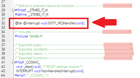
Now check the top parts of the stm8s_it.h and stm8s_it.c files respectively.
stm8s_it.h
stm8s_it.c
These must be coded.
Explanation
Most part of the code is same as previous codes and so I won’t be going through them again. However, there’s something new:
void EXTI_setup(void)
{
ITC_DeInit();
ITC_SetSoftwarePriority(ITC_IRQ_PORTB, ITC_PRIORITYLEVEL_0);
EXTI_DeInit();
EXTI_SetExtIntSensitivity(EXTI_PORT_GPIOB, EXTI_SENSITIVITY_FALL_ONLY);
EXTI_SetTLISensitivity(EXTI_TLISENSITIVITY_FALL_ONLY);
enableInterrupts();
}
This function is where we are setting up the external interrupt. The first two lines deinitiate the interrupt controller and set priority while initiating it. It is not mandatory unless you want to set interrupt priority. Then we configure the external interrupt on PORTB pins. We also set the edge that will invoke an interrupt. Finally, we enable global interrupt. There goes the main.c file
Now it’s time to explain the stm8_interrupt_vector.c file. The top part of this file must include this line #include “stm8s_it.h”. It must also have the following section commented out:
//@far @interrupt void NonHandledInterrupt (void)
//{
/* in order to detect unexpected events during development,
it is recommended to set a breakpoint on the following instruction
*/
// return;
//}
We need to let our compiler know the name of the function that it should call when a particular interrupt is triggered. There are two parts for that. Firstly, the interrupt vector address and secondly the name of the function. This is reason for this line:
{0x82, (interrupt_handler_t)EXTI1_IRQHandler}, /* irq4 */
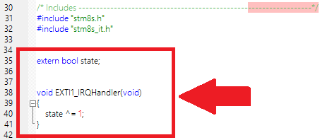
Lastly, the stm8s_it.h and stm8s_it.c files contain the prototype and the function that will execute the interrupt service routine (ISR). In our case, the ISR will change the logic state of the Boolean variable state. This will alter that flashing rate in the main loop.
Demo
|
|
Good morning , i am using stm8s003f3 for programming , i am using cosmic complier for programming,
Statement : i want to create a millis() function so that i can calculate timer between events.
i have done some programming but not able to create millis(), project bulid succesfully. but there is no output.
below i am attaching my code…..
////////////////////Tim4millis.c file ////////////
#include “tim4millis.h”
//__IO uint32_t current_millis = 0; //–IO: volatile read/write
volatile uint32_t current_millis = 0;
//this entire function using ST’s code
void TIM4_init(void)
{
CLK_HSIPrescalerConfig(CLK_PRESCALER_HSIDIV1); //f_master = HSI = 16Mhz
/* TIM4 configuration:
– TIM4CLK is set to 16 MHz, the TIM4 Prescaler is equal to 128 so the TIM1 counter
clock used is 16 MHz / 128 = 125 000 Hz
– With 125 000 Hz we can generate time base:
max time base is 2.048 ms if TIM4_PERIOD = 255 –> (255 + 1) / 125000 = 2.048 ms
min time base is 0.016 ms if TIM4_PERIOD = 1 –> ( 1 + 1) / 125000 = 0.016 ms
– In this example we need to generate a time base equal to 1 ms
so TIM4_PERIOD = (0.001 * 125000 – 1) = 124 */
/* Time base configuration */
TIM4_TimeBaseInit(TIM4_PRESCALER_128, TIM4_PERIOD);
/* Clear TIM4 update flag */
TIM4_ClearFlag(TIM4_FLAG_UPDATE);
/* Enable update interrupt */
TIM4_ITConfig(TIM4_IT_UPDATE, ENABLE);
/* enable interrupts */
enableInterrupts();
/* Enable TIM4 */
TIM4_Cmd(ENABLE);
}
uint32_t millis(void)
{
return current_millis;
}
//Interupt event, happen every 1 ms
INTERRUPT_HANDLER(TIM4_UPD_OVF_IRQHandler, 23)
{
//increase 1, for millis() function
current_millis ++;
TIM4_ClearITPendingBit(TIM4_IT_UPDATE);
}
///////////////////////////tim4millis.h////////////////////
#ifndef TIM4MILLIS_H_
#define TIM4MILLIS_H_
#include “stm8s.h”
#define TIM4_PERIOD 124
//volatile uint32_t current_millis
void TIM4_init(void);
uint32_t millis(void);
#endif
/////main.c file////
#include “stm8s_conf.h”
#include “tim4millis.h”
#define blinkInterval 100
uint32_t lastBlink = 0;
uint16_t currentTime = 0;
int main( void )
{
//setup clock
// CLK_DeInit();
TIM4_init(); //already setup f_Master = HSI/1 = 16MHz
GPIO_DeInit(GPIOB);
GPIO_Init(GPIOB, GPIO_PIN_5, GPIO_MODE_OUT_PP_LOW_SLOW);
while(1)
{
currentTime = millis();
if (currentTime – lastBlink >= blinkInterval)
{
GPIO_WriteLow(GPIOB, GPIO_PIN_5);
lastBlink = currentTime;
}
}
// return 0; //remove Warning[Pe111]
}
please help me out……….
thanks and regards
Ankur Bhatt
The best way to implement millis() function is to start a timer at boot time and have it increase a 32-bit variable every millisecond upon its overflow interrupt….
can you give me a snippet of code
my timer is working but the overflow is not working : for checking that i am toggling led but there is no led is working here i am attaching snippet of my code
@far @interrupt void TIM1_UPD_OVF_IRQHandler(void)
{
millis_counter++; // Increment milliseconds counter
GPIOB->ODR ^= (1 <SR1 &= ~TIM1_SR1_UIF; // Clear update interrupt flag
}
// ? Return the current milliseconds count
uint32_t millis(void)
{
uint32_t ms;
disableInterrupts();
ms = millis_counter;
enableInterrupts();
return ms;
}
Thank you for your great tutorials. They are priceless.
One question regarding the initialization of TIM2:
Why you use 1000 for “TIM2_Pulse” in TIM2_OC1Init()? Couldn’t you use instead the 625 and save the very next instruction “TIM2_SetCompare1”?
Regards Mario
typo mistake it seems….
Hi Shawon,
Thanks for the AWD tutorial https://embedded-lab.com/blog/starting-stm8-microcontrollers/14/. I dont see an LED flashing connected to PD0 as you have mentioned in the code/article. Will the AWD work in single shot mode or it has to be in continues conversion mode?
Regards
Sajeev
Very interesting article
hi sir…
I am getting this error at compile time…………. please help me.
Compiling main.c…
cxstm8 +mods0 +debug -pxp -no -pp -l -i”C:\Program Files (x86)\COSMIC\FSE_Compilers\Hstm8″ -clDebug\ -coDebug\ main.c
#error cpstm8 C:\Program Files (x86)\COSMIC\FSE_Compilers\CXSTM8\HSTM8\mods0.h:1 FlexLM License file does not support this version.
main.c:
The command: “cxstm8 +mods0 +debug -pxp -no -pp -l -i”C:\Program Files (x86)\COSMIC\FSE_Compilers\Hstm8″ -clDebug\ -coDebug\ main.c” has failed, the returned value is: 1
exit code=1.
it says right there your license file is the issue
Hi Shawon Shahryiar, I’m using stm8s003f3 chip, And I want to capture the PWM signal from PC7 which is Tim1_Channel 2.
And I Refer to your code and make the following changes.
“`
void GPIO_setup(void)
{
GPIO_DeInit(GPIOC);
GPIO_Init(GPIOC, GPIO_PIN_7, GPIO_MODE_IN_FL_NO_IT);
}
void TIM1_setup(void)
{
TIM1_DeInit();
TIM1_TimeBaseInit(2000, TIM1_COUNTERMODE_UP, 55535, 1);
TIM1_ICInit(TIM1_CHANNEL_2, TIM1_ICPOLARITY_RISING,
TIM1_ICSELECTION_DIRECTTI, 1, 1);
TIM1_ITConfig(TIM1_IT_UPDATE, ENABLE);
TIM1_ITConfig(TIM1_IT_CC2, ENABLE);
TIM1_Cmd(ENABLE);
enableInterrupts();
}
“`
And because I’m using iar embedded Dev environment for stm8, so I using following format IRQ function
“`
/**
* @brief Timer1 Capture/Compare Interrupt routine
* @param None
* @retval
* None
*/
INTERRUPT_HANDLER(TIM1_CAP_COM_IRQHandler, 12)
{
if (TIM1_GetITStatus(TIM1_IT_CC2))
{
…
}
}
“`
But when I set breakpoint in this IRQ_Handler function in “if” line, and make sure the PWM signal is coming in PC7 pin.
It just connot enter the IRQ function…
I used oscilloscope to make sure there is an signal into the PC7, but it just cannot enter the Interrupt service function TAT
Can you give me some advice on how to debug it? I would be appreciate it!!
Can I use the void TIM1_CH1_CCP_IRQHandler(void) ; function to toggle a led each time I turn my encoder? I’m trying to do this but when I scroll the encoder it reaches the interrupt function only after the overflow.
Helo Sir
I am trayig to read RMS voltage on stm8s003k3 but i read only +voltage not – voltage my signal is booth side – side and positive side plesase help me i am also read FFT term but i cant understand it Kindly Help me
Although not with STM8, this should surely help:
https://libstock.mikroe.com/projects/view/4754/estimating-ac-line-frequency-while-measuring-rms-voltage
Thank you so much for these tutorials … in fact I learned a lot here … but I am not very clear about a few concepts like timer capture.
I want to read a frequency of around 200 to 500 kHz, (actual reading is not so important, I just want to detect frequency variations) which values am I supposed to put in my code ?
Please HELP !!!
Chunks from my code are as below:
…
CLK_HSICmd(ENABLE); // high speed internal clock enabled (16MHz)
…
CLK_HSIPrescalerConfig(CLK_PRESCALER_HSIDIV2); // cpu clock
CLK_SYSCLKConfig(CLK_PRESCALER_CPUDIV1); // pripheral clock
…
CLK_PeripheralClockConfig(CLK_PERIPHERAL_UART1, ENABLE); // uart enabled
CLK_PeripheralClockConfig(CLK_PERIPHERAL_TIMER1, ENABLE); // timer1 enabled
…
// Frequency reading
TIM1_DeInit();
TIM1_TimeBaseInit(
2, // prescalar
TIM1_COUNTERMODE_UP, // up counting mode
65000, // period
1 // repitition
);
TIM1_ICInit(
TIM1_CHANNEL_1, // input channel 1
TIM1_ICPOLARITY_RISING, //rising edge input
TIM1_ICSELECTION_DIRECTTI, //
10, // input capture prescalar
1 // filter
);
TIM1_ITConfig(TIM1_IT_UPDATE, ENABLE);
TIM1_ITConfig(TIM1_IT_CC1, ENABLE);
TIM1_Cmd(ENABLE);
enableInterrupts();
Hello to All. STM8AF6213. I am at the stage where I did the first compile yet I see no sign of a code assistant. Does it need to be enabled somewhere? I glanced through the menus and saw no sign of such a setting. Any help would be appreciated. Thanks, Ted.
just hit Control + Space in your keyboard….
Thank you very much SS!
How could you download the cosmic compiler.download link doesn’t work.
https://www.cosmic-software.com/compiler.php
I have been trying for a very long time but couldn’t reach it.download button does not work.”Always The connection has timed out appeared”.Is there any way to get the software and key.
may be you should try a VPN like Hide.Me
I want to know how i can put 15 minute timer in stm8l microcontroller ? I want to count 15 minute and also perform operation in that time? Can i use timer4 , clock function , RTC?
Hi sir, Thank you very much for making all of these beneficial tutorials.
I have a problem. Please resolve it.
I am using the stm8s003f3p6 development board.
In my board TIM1_CH1 is on pin PC6, I have configured it as below instead of PC1 as you did.
I am using the “stm8s103_serial.h” library instead of LCD to print the time period.
Below is the code:
///////////////////////////////////////////////////////////
#include “STM8S.h”
#include “stm8s103_serial.h”
unsigned int overflow_count;
unsigned long pulse_ticks;
unsigned long start_time;
unsigned long end_time;
unsigned long int time_period;
void clock_setup(void);
void GPIO_setup(void);
void TIM1_setup(void);
void TIM2_setup(void);
void delay_ms (int ms) //Function Definition
{int i,j;
for (i=0; i<=ms; i++)
for (j=0; j<120; j++) // Nop = Fosc/4
_asm("nop"); //Perform no operation //assembly code
}
void main()
{
int cnt = 0;
Serial_begin(9600);
Serial_print_string("***RESET");
clock_setup();
GPIO_setup();
TIM1_setup();
TIM2_setup();
while(TRUE)
{
time_period = pulse_ticks;
Serial_print_char(time_period);
delay_ms(1000);
};
}
void clock_setup(void)
{
CLK_DeInit();
CLK_HSECmd(DISABLE);
CLK_LSICmd(DISABLE);
CLK_HSICmd(ENABLE);
while(CLK_GetFlagStatus(CLK_FLAG_HSIRDY) == FALSE);
CLK_ClockSwitchCmd(ENABLE);
CLK_HSIPrescalerConfig(CLK_PRESCALER_HSIDIV8);
CLK_SYSCLKConfig(CLK_PRESCALER_CPUDIV2);
CLK_ClockSwitchConfig(CLK_SWITCHMODE_AUTO, CLK_SOURCE_HSI,
DISABLE, CLK_CURRENTCLOCKSTATE_ENABLE);
CLK_PeripheralClockConfig(CLK_PERIPHERAL_SPI, DISABLE);
CLK_PeripheralClockConfig(CLK_PERIPHERAL_I2C, DISABLE);
CLK_PeripheralClockConfig(CLK_PERIPHERAL_ADC, DISABLE);
CLK_PeripheralClockConfig(CLK_PERIPHERAL_AWU, DISABLE);
CLK_PeripheralClockConfig(CLK_PERIPHERAL_UART1, ENABLE);
CLK_PeripheralClockConfig(CLK_PERIPHERAL_TIMER1, ENABLE);
CLK_PeripheralClockConfig(CLK_PERIPHERAL_TIMER2, ENABLE);
CLK_PeripheralClockConfig(CLK_PERIPHERAL_TIMER4, DISABLE);
}
void GPIO_setup(void)
{
GPIO_DeInit(GPIOC);
GPIO_Init(GPIOC, GPIO_PIN_6, GPIO_MODE_IN_FL_NO_IT);
GPIO_DeInit(GPIOD);
GPIO_Init(GPIOD, GPIO_PIN_4, GPIO_MODE_OUT_PP_HIGH_FAST);
}
void TIM1_setup(void)
{
TIM1_DeInit();
TIM1_TimeBaseInit(2000, TIM1_COUNTERMODE_UP, 55535, 1);
TIM1_ICInit(TIM1_CHANNEL_1, TIM1_ICPOLARITY_RISING,
TIM1_ICSELECTION_DIRECTTI, 1, 1);
TIM1_ITConfig(TIM1_IT_UPDATE, ENABLE);
TIM1_ITConfig(TIM1_IT_CC1, ENABLE);
TIM1_Cmd(ENABLE);
enableInterrupts();
}
void TIM2_setup(void)
{
TIM2_DeInit();
TIM2_TimeBaseInit(1,16550);//ARR = 16550 for 60Hz,1 as prescaler
TIM2_OC1Init(TIM2_OCMODE_PWM2, TIM2_OUTPUTSTATE_ENABLE, 0,
TIM2_OCPOLARITY_LOW);
TIM2_SetCompare1(8225);//16550/2 = 50% duty
TIM2_Cmd(ENABLE);
}
@far @interrupt void TIM1_UPD_IRQHandler(void)
{
overflow_count++;
TIM1_ClearITPendingBit(TIM1_IT_UPDATE);
TIM1_ClearFlag(TIM1_FLAG_UPDATE);
}
@far @interrupt void TIM1_CH1_CCP_IRQHandler(void)
{
end_time = TIM1_GetCapture1();
pulse_ticks = ((overflow_count << 16) – start_time + end_time);
start_time = end_time;
overflow_count = 0;
TIM1_ClearITPendingBit(TIM1_IT_CC1);
TIM1_ClearFlag(TIM1_FLAG_CC1);
}
///////////////////////////////////////////////////////////////////
thanks for sharing code , are you trying to capture capture the duty cycles ? , can you tell what error are facing .
Hi sir, Thank you very much for making all of these beneficial tutorials.
I have a problem. Please resolve it.
I am using the stm8s003f3p6 development board.
In my board TIM1_CH1 is on pin PC6, I have configured it as below instead of PC1 as you did.
I am using the “stm8s103_serial.h” library instead of LCD to print the time period.
Below is the code:
///////////////////////////////////////////////////////////
#include “STM8S.h”
#include “stm8s103_serial.h”
unsigned int overflow_count;
unsigned long pulse_ticks;
unsigned long start_time;
unsigned long end_time;
unsigned long int time_period;
void clock_setup(void);
void GPIO_setup(void);
void TIM1_setup(void);
void TIM2_setup(void);
void delay_ms (int ms) //Function Definition
{int i,j;
for (i=0; i<=ms; i++)
for (j=0; j<120; j++) // Nop = Fosc/4
_asm("nop"); //Perform no operation //assembly code
}
void main()
{
int cnt = 0;
Serial_begin(9600);
Serial_print_string("***RESET");
clock_setup();
GPIO_setup();
TIM1_setup();
TIM2_setup();
while(TRUE)
{
time_period = pulse_ticks;
Serial_print_char(time_period);
delay_ms(1000);
};
}
void clock_setup(void)
{
CLK_DeInit();
CLK_HSECmd(DISABLE);
CLK_LSICmd(DISABLE);
CLK_HSICmd(ENABLE);
while(CLK_GetFlagStatus(CLK_FLAG_HSIRDY) == FALSE);
CLK_ClockSwitchCmd(ENABLE);
CLK_HSIPrescalerConfig(CLK_PRESCALER_HSIDIV8);
CLK_SYSCLKConfig(CLK_PRESCALER_CPUDIV2);
CLK_ClockSwitchConfig(CLK_SWITCHMODE_AUTO, CLK_SOURCE_HSI,
DISABLE, CLK_CURRENTCLOCKSTATE_ENABLE);
CLK_PeripheralClockConfig(CLK_PERIPHERAL_SPI, DISABLE);
CLK_PeripheralClockConfig(CLK_PERIPHERAL_I2C, DISABLE);
CLK_PeripheralClockConfig(CLK_PERIPHERAL_ADC, DISABLE);
CLK_PeripheralClockConfig(CLK_PERIPHERAL_AWU, DISABLE);
CLK_PeripheralClockConfig(CLK_PERIPHERAL_UART1, ENABLE);
CLK_PeripheralClockConfig(CLK_PERIPHERAL_TIMER1, ENABLE);
CLK_PeripheralClockConfig(CLK_PERIPHERAL_TIMER2, ENABLE);
CLK_PeripheralClockConfig(CLK_PERIPHERAL_TIMER4, DISABLE);
}
void GPIO_setup(void)
{
GPIO_DeInit(GPIOC);
GPIO_Init(GPIOC, GPIO_PIN_6, GPIO_MODE_IN_FL_NO_IT);
GPIO_DeInit(GPIOD);
GPIO_Init(GPIOD, GPIO_PIN_4, GPIO_MODE_OUT_PP_HIGH_FAST);
}
void TIM1_setup(void)
{
TIM1_DeInit();
TIM1_TimeBaseInit(2000, TIM1_COUNTERMODE_UP, 55535, 1);
TIM1_ICInit(TIM1_CHANNEL_1, TIM1_ICPOLARITY_RISING,
TIM1_ICSELECTION_DIRECTTI, 1, 1);
TIM1_ITConfig(TIM1_IT_UPDATE, ENABLE);
TIM1_ITConfig(TIM1_IT_CC1, ENABLE);
TIM1_Cmd(ENABLE);
enableInterrupts();
}
void TIM2_setup(void)
{
TIM2_DeInit();
TIM2_TimeBaseInit(1,16550);//ARR = 16550 for 60Hz,1 as prescaler
TIM2_OC1Init(TIM2_OCMODE_PWM2, TIM2_OUTPUTSTATE_ENABLE, 0,
TIM2_OCPOLARITY_LOW);
TIM2_SetCompare1(8225);//16550/2 = 50% duty
TIM2_Cmd(ENABLE);
}
@far @interrupt void TIM1_UPD_IRQHandler(void)
{
overflow_count++;
TIM1_ClearITPendingBit(TIM1_IT_UPDATE);
TIM1_ClearFlag(TIM1_FLAG_UPDATE);
}
@far @interrupt void TIM1_CH1_CCP_IRQHandler(void)
{
end_time = TIM1_GetCapture1();
pulse_ticks = ((overflow_count << 16) – start_time + end_time);
start_time = end_time;
overflow_count = 0;
TIM1_ClearITPendingBit(TIM1_IT_CC1);
TIM1_ClearFlag(TIM1_FLAG_CC1);
}
///////////////////////////////////////////////////////////////////
Thank you very much for making all of these beneficial tutorials.
I have a problem. Please resolve it.
I am using the stm8s003f3p6 development board.
In my board TIM1_CH1 is on pin PC6, I have configured it as below instead of PC1.
I am using the “stm8s103_serial.h” library instead of LCD to print the time period.
Below is the code:
///////////////////////////////////////////////////////////
#include “STM8S.h”
#include “stm8s103_serial.h”
unsigned int overflow_count;
unsigned long pulse_ticks;
unsigned long start_time;
unsigned long end_time;
unsigned long int time_period;
void clock_setup(void);
void GPIO_setup(void);
void TIM1_setup(void);
void TIM2_setup(void);
void delay_ms (int ms) //Function Definition
{int i,j;
for (i=0; i<=ms; i++)
for (j=0; j<120; j++) // Nop = Fosc/4
_asm("nop"); //Perform no operation //assembly code
}
void main()
{
int cnt = 0;
Serial_begin(9600);
Serial_print_string("***RESET");
clock_setup();
GPIO_setup();
TIM1_setup();
TIM2_setup();
while(TRUE)
{
time_period = pulse_ticks;
Serial_print_int(time_period);
delay_ms(1000);
};
}
void clock_setup(void)
{
CLK_DeInit();
CLK_HSECmd(DISABLE);
CLK_LSICmd(DISABLE);
CLK_HSICmd(ENABLE);
while(CLK_GetFlagStatus(CLK_FLAG_HSIRDY) == FALSE);
CLK_ClockSwitchCmd(ENABLE);
CLK_HSIPrescalerConfig(CLK_PRESCALER_HSIDIV8); //2MHz
CLK_SYSCLKConfig(CLK_PRESCALER_CPUDIV2); //1KHz
CLK_ClockSwitchConfig(CLK_SWITCHMODE_AUTO, CLK_SOURCE_HSI,
DISABLE, CLK_CURRENTCLOCKSTATE_ENABLE);
CLK_PeripheralClockConfig(CLK_PERIPHERAL_SPI, DISABLE);
CLK_PeripheralClockConfig(CLK_PERIPHERAL_I2C, DISABLE);
CLK_PeripheralClockConfig(CLK_PERIPHERAL_ADC, DISABLE);
CLK_PeripheralClockConfig(CLK_PERIPHERAL_AWU, DISABLE);
CLK_PeripheralClockConfig(CLK_PERIPHERAL_UART1, ENABLE);
CLK_PeripheralClockConfig(CLK_PERIPHERAL_TIMER1, ENABLE);
CLK_PeripheralClockConfig(CLK_PERIPHERAL_TIMER2, ENABLE);
CLK_PeripheralClockConfig(CLK_PERIPHERAL_TIMER4, DISABLE);
}
void GPIO_setup(void)
{
GPIO_DeInit(GPIOC);
GPIO_Init(GPIOC, GPIO_PIN_6, GPIO_MODE_IN_FL_NO_IT);
GPIO_DeInit(GPIOD);
GPIO_Init(GPIOD, GPIO_PIN_4, GPIO_MODE_OUT_PP_HIGH_FAST);
}
void TIM1_setup(void)
{
TIM1_DeInit();
TIM1_TimeBaseInit(2000, TIM1_COUNTERMODE_UP, 55535, 1);
TIM1_ICInit(TIM1_CHANNEL_1, TIM1_ICPOLARITY_RISING,
TIM1_ICSELECTION_DIRECTTI, 1, 1);
TIM1_ITConfig(TIM1_IT_UPDATE, ENABLE);
TIM1_ITConfig(TIM1_IT_CC1, ENABLE);
TIM1_Cmd(ENABLE);
enableInterrupts();
}
void TIM2_setup(void)
{
TIM2_DeInit();
TIM2_TimeBaseInit(1,16550);//ARR = 16550 for 60Hz,1 as prescaler
TIM2_OC1Init(TIM2_OCMODE_PWM2, TIM2_OUTPUTSTATE_ENABLE, 0,
TIM2_OCPOLARITY_LOW);
TIM2_SetCompare1(8225);//16550/2 = 50% duty
TIM2_Cmd(ENABLE);
}
@far @interrupt void TIM1_UPD_IRQHandler(void)
{
overflow_count++;
TIM1_ClearITPendingBit(TIM1_IT_UPDATE);
TIM1_ClearFlag(TIM1_FLAG_UPDATE);
}
@far @interrupt void TIM1_CH1_CCP_IRQHandler(void)
{
end_time = TIM1_GetCapture1();
pulse_ticks = ((overflow_count << 16) – start_time + end_time);
start_time = end_time;
overflow_count = 0;
TIM1_ClearITPendingBit(TIM1_IT_CC1);
TIM1_ClearFlag(TIM1_FLAG_CC1);
}
///////////////////////////////////////////////////////////////////
thanks for sharing this code, are you trying to capture duty cycles .
Thank you for making all of these good tutorials.
I have some problems
----------- Project blink - STM8 Cosmic - Configuration Debug -------------
Compiling d:\stm8ssaucefiles\delay.c...
cxstm8 -id:\stm8ssaucefiles +debug -pxp -no -l +mods0 -pp -i"C:\Program Files (x86)\COSMIC\FSE_Compilers\CXSTM8\Hstm8" -clDebug\ -coDebug\ d:\stm8ssaucefiles\delay.c
d:\stm8ssaucefiles\delay.c:
Compiling stm8_interrupt_vector.c...
cxstm8 -id:\stm8ssaucefiles +debug -pxp -no -l +mods0 -pp -i"C:\Program Files (x86)\COSMIC\FSE_Compilers\CXSTM8\Hstm8" -clDebug\ -coDebug\ stm8_interrupt_vector.c
stm8_interrupt_vector.c:
Running Linker
clnk -m Debug\blink.map -l"C:\Program Files (x86)\COSMIC\FSE_Compilers\CXSTM8\Lib" -o Debug\blink.sm8 Debug\blink.lkf
#error clnk Debug\blink.lkf:1 symbol _GPIO_DeInit not defined (Debug\main.o )
#error clnk Debug\blink.lkf:1 symbol _GPIO_Init not defined (Debug\main.o )
#error clnk Debug\blink.lkf:1 symbol _GPIO_ReadInputPin not defined (Debug\main.o )
#error clnk Debug\blink.lkf:1 symbol _GPIO_WriteReverse not defined (Debug\main.o )
The command: "clnk -m Debug\blink.map -l"C:\Program Files (x86)\COSMIC\FSE_Compilers\CXSTM8\Lib" -o Debug\blink.sm8 Debug\blink.lkf " has failed, the returned value is: 1
exit code=1.
blink.elf - 6 error(s), 0 warning(s)
Is there anything i could do to resolve this error ?
Because in your other tutorial (Driving LCD with I2C), i have this kind of error too (with I2C addition)
Once again,
Thank you for making all of these good tutorials.
looks like that project is not finding the GPIO files….
It is.
in this case i should add the stm8s_gpio.c & stm8s_gpio.h from SPL into project.
Thanks dude
yes you should add these files….
Where can i get complete lesion in pdf file
I am trying to implement simple spi communication between 2 stm8s. Sending 0x04( address of pin2) and passing the received data as argument to GPIO high function so that LED connected at PORT D PIN 2 will glow. Master code is working properly, degugging properly, but in slave the TXE is not becoming 1 and program is stuck there only. Does any one can help locating the problem if its in code?
Master code:
#include “stm8s.h”
#include “stm8s_gpio.h”
#include “stm8s_spi.h”
#include “stm8s_clk.h”
void GPIO_setup(void);
void clock_setup(void);
void GPIO_setup(void)
{ GPIO_DeInit(GPIOC);
GPIO_DeInit(GPIOB);
GPIO_DeInit(GPIOD);
GPIO_DeInit(GPIOA);
// led pin
GPIO_Init(GPIOA, GPIO_PIN_3,GPIO_MODE_OUT_PP_HIGH_FAST);//NSS
GPIO_Init(GPIOC,GPIO_PIN_5, GPIO_MODE_OUT_PP_HIGH_FAST );//sck pin 5
GPIO_Init(GPIOC, GPIO_PIN_6, GPIO_MODE_OUT_PP_HIGH_FAST);//mosi pin 6
GPIO_Init(GPIOC, GPIO_PIN_7, GPIO_MODE_IN_PU_NO_IT);//miso pin 7
}
void clock_setup(void)
{
CLK_DeInit();
CLK_HSECmd(DISABLE);
CLK_LSICmd(DISABLE);
CLK_HSICmd(ENABLE);
while(CLK_GetFlagStatus(CLK_FLAG_HSIRDY) == FALSE);
CLK_ClockSwitchCmd(ENABLE);
CLK_HSIPrescalerConfig(CLK_PRESCALER_HSIDIV1);//00
CLK_SYSCLKConfig(CLK_PRESCALER_CPUDIV8);//0x80
CLK_ClockSwitchConfig(CLK_SWITCHMODE_AUTO,CLK_SOURCE_HSI,DISABLE, CLK_CURRENTCLOCKSTATE_ENABLE);
CLK_PeripheralClockConfig(CLK_PCKENR1_SPI,ENABLE);
}
void main(void)
{
clock_setup();
GPIO_setup();
SPI_DeInit();
SPI_Init(SPI_FIRSTBIT_MSB, SPI_BAUDRATEPRESCALER_2, SPI_MODE_MASTER, SPI_CLOCKPOLARITY_HIGH,
SPI_CLOCKPHASE_1EDGE,SPI_DATADIRECTION_2LINES_FULLDUPLEX,SPI_NSS_SOFT,0x00);
SPI_NSSInternalSoftwareCmd(DISABLE);
SPI_Cmd(ENABLE);
GPIO_WriteLow(GPIOA,GPIO_PIN_3);// pull nss low
SPI_SendData(0x04);//pin 2 address
while(SPI_GetFlagStatus(SPI_FLAG_TXE)== RESET);
while(SPI_GetFlagStatus(SPI_FLAG_BSY));
GPIO_WriteHigh(GPIOA,GPIO_PIN_3);// pull NSS high
SPI_Cmd(DISABLE);// disable spi
}
SLAVE CODE:
#define STM8S103
#include “stm8s.h”
#include “stm8s_clk.h”
#include “stm8s_gpio.h”
#include “stm8s_spi.h”
uint8_t RxBuffer2=0;
void main(void)
{CLK_DeInit();
CLK_PeripheralClockConfig(CLK_PCKENR1_SPI,ENABLE);
GPIO_DeInit(GPIOD);
GPIO_DeInit(GPIOA);
GPIO_DeInit(GPIOC);
GPIO_DeInit(GPIOB);
GPIO_Init(GPIOC,GPIO_PIN_5,GPIO_MODE_IN_PU_NO_IT);//sck pin 5
GPIO_Init(GPIOC,GPIO_PIN_6,GPIO_MODE_IN_PU_NO_IT );//mosi pin 6
GPIO_Init(GPIOC,GPIO_PIN_7,GPIO_MODE_OUT_PP_HIGH_FAST);//miso
GPIO_Init(GPIOA,GPIO_PIN_3,GPIO_MODE_IN_PU_NO_IT);//nss
SPI_DeInit();
SPI_Init(SPI_FIRSTBIT_MSB, SPI_BAUDRATEPRESCALER_2, SPI_MODE_SLAVE, SPI_CLOCKPOLARITY_HIGH,
SPI_CLOCKPHASE_1EDGE,SPI_DATADIRECTION_2LINES_FULLDUPLEX,SPI_NSS_SOFT,0x00);
SPI_NSSInternalSoftwareCmd(DISABLE);
SPI_Cmd(ENABLE);
SPI_SendData(0x04);//pin 2
while(SPI_GetFlagStatus(SPI_FLAG_TXE)== RESET);
while (SPI_GetFlagStatus(SPI_FLAG_RXNE) == RESET);
RxBuffer2 = SPI_ReceiveData();
GPIO_Init(GPIOD,RxBuffer2,GPIO_MODE_OUT_PP_HIGH_SLOW);// turn on led at this address
GPIO_WriteHigh(GPIOD,RxBuffer2);
while(SPI_GetFlagStatus(SPI_FLAG_BSY));
}
Hello Shawon,
Thank you so much for creating such an amazing tutorial on STM8 !!! , highly appreciate your efforts.
Just wanted to add that one can also use STM Studio to watch variables in run time. This is quite a handy feature which perhaps also removes the need to use a LCD / serial debug to do the same.
Note: I had done quite a rookie mistake by using a LCD which had the SWIM pin used as EN of the LCD, so this created a conflict. just avoid using swim pin for any other purpose other than debugging.
A similar feature under the name quickwatch is also available under the debugging option of STVD however for some reason the values were not updating in it.
Let me know if someone has figured this out.
hi shawon
i am interfacing mpu6050 with stm8s003f3 but getting constant or garbage values everytime. can you please help me out.
Hi shawon
I notice that you have given the address of Bh1750 (0x46) but when i read the datasheet i found it as (0x23) . can you tell why you have don this??
Hi,
I am having problem configuring timer 2 / timer 3 tick per 2us.
No matter how i set the configuration the timer tick can never go lower than 7 microsecond.
Need help to check which part of the code below is wrong. Or missing some important part.
Here is my setup.
main.c
static void CLK_Config(void)
{
CLK_SYSCLKConfig(CLK_PRESCALER_CPUDIV1);
/* Configure the HSI prescaler to the optimal value */
CLK_SYSCLKConfig(CLK_PRESCALER_HSIDIV1);
CLK_CCOConfig(CLK_OUTPUT_MASTER);
/* Configure the system clock to use HSE clock source */
CLK_ClockSwitchConfig(CLK_SWITCHMODE_AUTO, CLK_SOURCE_HSI, DISABLE, CLK_CURRENTCLOCKSTATE_DISABLE);
}
void TIM3_Config(void)
{
TIM3_DeInit();
/* Time base configuration */
TIM3_TimeBaseInit(TIM3_PRESCALER_2,15);
/* Clear TIM3 update flag */
TIM3_ClearFlag(TIM3_FLAG_UPDATE);
/* Enable update interrupt */
TIM3_ITConfig(TIM3_IT_UPDATE, ENABLE);
}
stm8s_it.c
INTERRUPT_HANDLER(TIM3_UPD_OVF_BRK_IRQHandler, 15)
{
/* In order to detect unexpected events during development,
it is recommended to set a breakpoint on the following instruction.
*/
GPIO_WriteReverse(GPIOD,GPIO_PIN_3);
TimingDelay_Decrement();
TIM3_ClearITPendingBit(TIM3_IT_UPDATE);
}
Hi Shawon i am interfacing mpu6050 with stm8s003f3. i used the same configuration as you have used for Bh1750 eeprom but my controller gets hang.
void MPU6050_write(unsigned char cmd)
{
I2C_GenerateSTART(ENABLE);
while(!I2C_CheckEvent(I2C_EVENT_MASTER_MODE_SELECT));
I2C_Send7bitAddress(MPU6050_addr, I2C_DIRECTION_TX);
while(!I2C_CheckEvent(I2C_EVENT_MASTER_TRANSMITTER_MODE_SELECTED));
I2C_SendData(cmd);
while(!I2C_CheckEvent(I2C_EVENT_MASTER_BYTE_TRANSMITTED));
I2C_GenerateSTOP(ENABLE);
}
can you please telll me why this is happening.
any solution for this??
#error clnk Debug\icard_!.lkf:1 segment .text size overflow (619)
i am facing this error while initialize I2C. please help me
Because Cosmic compiler free version has limit of code size.
you can use IAR EW for STM8. but it has limit of 30days
Cosmic is fully free….
#error clnk Debug\icard_!.lkf:1 segment .text size overflow (619)
The command: “clnk -m Debug\icard_!.map -l”C:\Program Files\COSMIC\FSE_Compilers\Lib” -o Debug\icard_!.sm8 Debug\icard_!.lkf ” has failed, the returned value is: 1
exit code=1.
i am facing this error while initialize I2C. please help me
Hello,
First of all thanks a lot for this very educational series. I am trying the LCD program but can’t seem to get it to work. The LCD just won’t print anything. I have tried now 2 LCD 16×2 modules and both have same issue. Could you kindly help me with what can be causing this?
My set up – https://imgur.com/yVq5QkO
My Code :
#include “STM8S.h”
#include “lcd.h”
void clock_setup(void);
void GPIO_setup(void);
void delay_ms(long int n)
{
while(n–> 0);
}
void main(void)
{
char txt1[] = {“MICROARENA”};
char txt2[] = {“SShahryiar”};
char txt3[] = {“STM8S003K”};
char txt4[] = {“Discovery”};
unsigned char s = 0x00;
clock_setup();
GPIO_setup();
LCD_init();
LCD_clear_home();
LCD_goto(3, 0);
LCD_putstr(txt1);
LCD_goto(3, 1);
LCD_putstr(txt2);
delay_ms(4000);
LCD_clear_home();
for(s = 0; s < 9; s++)
{
LCD_goto((3 + s), 0);
LCD_putchar(txt3[s]);
delay_ms(90);
}
for(s = 0; s < 9; s++)
{
LCD_goto((3 + s), 1);
LCD_putchar(txt4[s]);
delay_ms(90);
}
while (TRUE);
}
void clock_setup(void)
{
CLK_DeInit();
CLK_HSECmd(DISABLE);
CLK_LSICmd(DISABLE);
CLK_HSICmd(ENABLE);
while(CLK_GetFlagStatus(CLK_FLAG_HSIRDY) == FALSE);
CLK_ClockSwitchCmd(ENABLE);
CLK_HSIPrescalerConfig(CLK_PRESCALER_HSIDIV8);
CLK_SYSCLKConfig(CLK_PRESCALER_CPUDIV1);
CLK_ClockSwitchConfig(CLK_SWITCHMODE_AUTO, CLK_SOURCE_HSI,
DISABLE, CLK_CURRENTCLOCKSTATE_ENABLE);
CLK_PeripheralClockConfig(CLK_PERIPHERAL_SPI, DISABLE);
CLK_PeripheralClockConfig(CLK_PERIPHERAL_I2C, DISABLE);
CLK_PeripheralClockConfig(CLK_PERIPHERAL_ADC, DISABLE);
CLK_PeripheralClockConfig(CLK_PERIPHERAL_AWU, DISABLE);
CLK_PeripheralClockConfig(CLK_PERIPHERAL_UART1, DISABLE);
CLK_PeripheralClockConfig(CLK_PERIPHERAL_TIMER1, DISABLE);
CLK_PeripheralClockConfig(CLK_PERIPHERAL_TIMER2, DISABLE);
CLK_PeripheralClockConfig(CLK_PERIPHERAL_TIMER4, DISABLE);
}
void GPIO_setup(void)
{
GPIO_DeInit(LCD_PORT);
}
Thanks again!
Used the same GPIOs as I did?
Yes :
#define LCD_PORT GPIOD
#define LCD_RS GPIO_PIN_2
#define LCD_EN GPIO_PIN_3
#define LCD_DB4 GPIO_PIN_4
#define LCD_DB5 GPIO_PIN_5
#define LCD_DB6 GPIO_PIN_6
#define LCD_DB7 GPIO_PIN_7
the only issue that looks to me troublesome is the delay function….
I now replaced the delay with the delay function from your repository. Similar issue again except that now I see blocks in both rows. Btw I am using IAR not STVD. Could that be an issue?
Now adjust contrast…. I think your issue is now solved….
Still the same issue. Could it because of some clock issue? Do I have to set the clock somewhere? Now I am using the project files from the library i downloaded from your repository. I have not changed any thing there.
May be the clock is too fast….
Hi, probably that is the issue. Which file do I change the clock? What speed are you using in this program
Hello, Why you used @far @interrupt before void EXT1_interrupt(void)?
As u mention in your article that stm8s is used for digital panel meter.so do you have any sample code or snippet for this applicaion.please reply me.
thanks
Sir , can u please tell me how u select this timer value in timer input capture tutorial in stm8s series .
Thanks for these amazing tutorial series how can we make this code to print floating point values to make it more accurate . The time period is only printing in int value .
Hi, Great Tutorial!
Do you know how to make it constant beep in a while loop instead of outside of while loop?
I tried below code but with no luck.
//CODE//
void main(void)
{
clock_setup();
GPIO_setup();
beeper_setup();
while(TRUE)
{
BEEP_Cmd(ENABLE);
};
}
Hi Shawon!
I’ve been studying your tutorials recently and they’ve been great.
I didn’t have a discovery board at first so I just tried to learn how to do the coding! And that was all right.
But now that I have bought a STM8s003f3p6 board and I’m trying to see my code run on board, I’ve encountered plenty of errors! I’d really appreciate it if you could help me! Thank you in advance.
First of all my board doesn’t come with a bulit-in st-link programmer. So I have bought a st-link/v2 programmer to connect my stm8 board to the PC. And here is my problem:
The st-link/v2 programmer is recognized by the PC and can be seen in the device manager. All connections from the programmer to the stm8 board are established, I mean nrst, swim, gnd and vdd. But when I try to program the board using STVP, this error pops up:
“Cannot communicate with the device! Check the swim cable connection and check all the needed pin connections on the swim connector.”
I have checked pin conncetion and I’ve surfed different websites but I can’t figure it out! Hope you can help me…
What happens why you try to read the chip?
You mean “what happens ((when)) you try to read the chip?”, right?
I just checked it and the same error occurs!
I also used IAR Embedded Workbench for STM8 just to see if makes any difference but again a similar error took place:
“Failed to set configuration with MCU name STM8S003F3: SWIM error [30006]: comm init error: chip does not answer”
I don’t know whether it’s because of the my PC’s drivers or some settings that I’m missing or anything else…
Some boards have the bug that the GND pin of connector is not connected to CPU/board ground. Please check continuity of all connector pins to CPU.
Hi,
In Window Watchdog Timer tutorial , Counter diagram is look like its wrong not 0x7F it is should be 0x3F. because i have referred the same diagram from the reference manual.
And can u please tell me the follow bit clearly ,
when you’re not pressing the key , if condition will satisfy or not ?, because it’s down-counter and need to change the counter diagram as per reference manual.
when you’re pressing the key, outside the window of watchdog refresh it get’s reset is my understanding is correct?
Hi Shawon
I used your “stm8s_delay.c” and “stm8s_delay.h” with my other source and header files.
But… delay is too long!!!
What is the reason?
Could be due to slow oscillator or clock source…. You must change
#define F_CPU 16000000ULthis line in the header file….
that’s correct
thanks
hi , where i can find these stm8s_delay.c” and “stm8s_delay.h” . not able to locate anywhere.
checkout the inc and src folders of my GitHub repo…..
Hello i am newbie on this controller i want to interface 4 digit 7 segment display to indicate measure voltage through the ADC and i have to configure my gpio adc timer and clk . thanks!!!
thanks for this lovely tutorial….i am new on this controller. i have doubt,How do i configure 4 digit 7 segment display and how to read data and display on the dispaly through the adc. i have to calculate current and voltage and display on segment .
which mode will be suitable for this conversion????
Hi Shawon,
First of all, thank you for this wonderful tutorial. While compiling code in STVP, I came across an unexpected error. When I deinitialize a port using
GPIO_DeInit(GPIOx); //x=port name
and declare a character using
char ch;
compiler throws error as
The command: “cxstm8 -i..\gpio_test\inc -iinc +debug -pxp -no -l +mods0 -pp -i”C:\Program Files (x86)\COSMIC\FSE_Compilers\CXSTM8\Hstm8″ -clDebug\ -coDebug\ main.c ” has failed, the returned value is: 1
exit code=1.
These two pieces of code do not go together. However, when I just use one of them. There is no error. Why is that?
Thank you
can anyone tell me how to use alternate function of the pin using pheriphral library?
for which MCU?
stm8s003f3
There is no alternative GPIO function in this device. Could you be specific why you are looking for alternative GPIOs?
HI,
Can you tell me the procedure to interface Seven segment displace because in th program, I cant find any thing related to seven segment, Like how you are providing serial clock and latch input to seven segment display?
thank you
Timer Interrupt (TIM4) example discusses about seven segment display. Have you not seen it?
Hi,
I am new to this stm8 .
I have a small doubt .
my doubt is “while configuring the interrupts, why we are commented or un-commented the particular part of the code
in the BASIC INTERRUPT VECTOR TABLE FOR STM8 devices file ”
//@far @interrupt void NonHandledInterrupt (void)
//{
/* in order to detect unexpected events during development,
it is recommended to set a breakpoint on the following instruction
*/
// return;
//}
this part you used in the above code .
Any specific reason for this commenting this section.
sorry for my poor English.
Thanks in advance .
Great work on this document. Highly appreciated.
I am using STM8S105K4 with PB0, PB1 PB2 and PB4 as ADC input pins. I have In my application i see when i use ADC measurement using following functions:
ADC1_Init(ADC1_CONVERSIONMODE_SINGLE,ADC1_CHANNEL_0|ADC1_CHANNEL_1|ADC1_CHANNEL_2|ADC1_CHANNEL_4|ADC1_CHANNEL_5,ADC1_PRESSEL_FCPU_D18, ADC1_EXTTRIG_GPIO, DISABLE, ADC1_ALIGN_RIGHT, ADC1_SCHMITTTRIG_CHANNEL0|ADC1_SCHMITTTRIG_CHANNEL1|ADC1_SCHMITTTRIG_CHANNEL2|ADC1_SCHMITTTRIG_CHANNEL4|ADC1_SCHMITTTRIG_CHANNEL5,DISABLE);
ADC1_Cmd(ENABLE);
I am seeing noise on PB0 pin and channel PB1, PB2 are reading 0 (even though there is significant voltage on pin) value when application is debugged. When i turn off ADC function completely noise goes away. so there is definatly some interaction on board with ADC noise. i am using HSI clk with 1Mhz frq.
Good article. I’m new to stm8. i was using stm32 till date. now I chose stm8s001j3 controller.
I’m able to compile code & open the light programmer. but it ends up saying “error: The specified module could not be found”
“error: Cannot load HaplSwim.dll”.
Am i missing something with respect to swim connection? I have left swim pin connected to ground & then is connected to ST-LinkV2.
kindly help out. Thanks.
BR,
Anantha R
seems like a programmer software issue….
Good tutorial, thanks, but I have a question about the GPIO configuration of SPI MOSI. In the SPI example code of STM8S/A Standard Peripherals Firmware Library, the GPIO of SPI MOSI, MISO are not configured.
If you setup SPI hardware, the MOSI-MISO GPIOs are automatically sets….
i use the code for my STM8S003F3P6 controller & i have changed the PIN PC2 and PC3 to Port B (due to PC2&PC3 is not available in stm8s003f3) also make changes in lcd.h &lcd.c. but while Build i found below errors. and i don’t know the meaning of error, kindly help me.
Compiling lcd.c…
cxstm8 +debug -pxp -no -l +mods0 -pp -i”C:\Program Files (x86)\COSMIC\FSE_Compilers\Hstm8″ -clDebug\ -coDebug\ lcd.c
#error cpstm8 stm8s.h:2826 bad #endif
lcd.c:
The command: “cxstm8 +debug -pxp -no -l +mods0 -pp -i”C:\Program Files (x86)\COSMIC\FSE_Compilers\Hstm8″ -clDebug\ -coDebug\ lcd.c ” has failed, the returned value is: 1
exit code=1.
uv_lcd_stvd_1.elf – 3 error(s), 0 warning(s)
so kindly give me the solution because i don’t understand why this error is appear.
Check email please…. I need to see your LCD code….
Is there anyway to send a float to the display? Or cast a float to a string to use the LCD_putstr function that is written?
Yes there’s a way…. I’ll send you in your gmail address….
Can you show me how to print float values?
My Gmail: mdjunaidahmed0123@gmail.com
Please reply or send me a mail.
Thank You.
Yes,same configuration for both adc1 0/1 channel.
void ADC1_setup(void)
{
ADC1_DeInit();
ADC1_Init(ADC1_CONVERSIONMODE_CONTINUOUS,
ADC1_CHANNEL_0, // on PB0 analog input EUT Mains voltage
ADC1_PRESSEL_FCPU_D8,
ADC1_EXTTRIG_GPIO,
DISABLE,
ADC1_ALIGN_RIGHT,
ADC1_SCHMITTTRIG_CHANNEL0,DISABLE);
“same for channell 1″….then:
ADC1_ConversionConfig(ADC1_CONVERSIONMODE_CONTINUOUS,
((ADC1_Channel_TypeDef)(ADC1_CHANNEL_0 | ADC1_CHANNEL_1)),
ADC1_ALIGN_RIGHT);
ADC1_DataBufferCmd(ENABLE);
ADC1_Cmd(ENABLE);
thank you for the answers!
First of all a big thank you for the work done!
I have a issue with ADC1 in stm8s105k4 device:for my project i have used ADC1 in scan mode (i have to measure two analog voltage),I used the code that you described in your course (Multi Channel ADC with Scan Mode).
I have enable AIN0(on PB0) and AIN1(on PB1) but the result is that only the reading on PB0 is continuos updated,the value on PB1 is updated only one time (after reset).
Do you have any suggestions?
Thanks!
Both channels have same settings?
Hi,
I am trying to compile the Source code for SM8S, and getting error
#error cpstm8 ..\..\stm8s_eval.h:127 “Please select first the STM8S EVAL board to be used (in stm8s_eval.h)”
I ALREADY DEFINED THE BOARD UNDER TOOL CHAIN, COULD YOU TELL ME WHERE I CAN DEFINE THE EVAL BOARD, ”
REGARDS,
I never tried to use this…. Can’t help in this regard….
You can try uncommenting the line respective to eval board you are using in “stm8s_eval.h”.
thank you so much sir for sharing good tutorials for us. i complete all your tutorials also done my minor project in stm8s. love from india.
Many thanks….
clnk -l”C:\Program Files (x86)\Common Files\Lib” -o Debug\alpha_lcd.sm8 -mDebug\alpha_lcd.map Debug\alpha_lcd.lkf
#error clnk Debug\alpha_lcd.lkf:79 Debug\stm8_interrupt_vector.o: symbol f_NonHandledInterrupt multiply defined (Debug\stm8s_it.o)
The command: “clnk -l”C:\Program Files (x86)\Common Files\Lib” -o Debug\alpha_lcd.sm8 -mDebug\alpha_lcd.map Debug\alpha_lcd.lkf ” has failed, the returned value is: 1
exit code=1.
lcd file add file stm8s_it.c compile error
lcd and external interrupt compile error
Compiling ..\stm8s_3f3_library\src\stm8s_it.c…
cxstm8 -i..\stm8s_3f3_library\inc +debug -pxp -no -l +mods0 -pp -i”C:\Program Files\COSMIC\FSE_Compilers\Hstm8″ -clDebug\ -coDebug\ ..\stm8s_3f3_library\src\stm8s_it.c
this error– ” #error cgstm8:0 x() unknown space: intrrupt ”
..\stm8s_3f3_library\src\stm8s_it.c:
The command: “cxstm8 -i..\stm8s_3f3_library\inc +debug -pxp -no -l +mods0 -pp -i”C:\Program Files\COSMIC\FSE_Compilers\Hstm8″ -clDebug\ -coDebug\ ..\stm8s_3f3_library\src\stm8s_it.c ” has failed, the returned value is: 1
exit code=1.
intrupt.elf – 3 error(s), 0 warning(s)
i dont know what i can do
Thank you so much for shering this kind of information. Sir something wrong with me after extract zip (spl) file i cannot find config.h and flash.h , please sir tell me what i can do ?
Try re-downloading….
Thank you, Shawon and Embedded Lab for these wonderful tutorials. I’d just like to ask if you’ve added a (preferably linked) index of their titles somewhere? As far as I can tell, one has to select a blind number (above) before one can tell what subject it’s a tutorial about!
Recommend that you use the PDF document of the tutorial.
Thank you for the example code. What series of steps should one take in order to migrate your code to a different MCU? I have an STM8TL52F4.
In the section “Preparing the Software Tools” I discussed what you need.
I used scan mode example from your example files, but its not updating ADC result when i change voltage on ADC pin. It keeps showing initial value.
Hello Sir
Sir i am little bit confuse about code size its ” s19 ” files is too big to controler memory
how can we know about our code how big it
Please Replay Me
Pingback: آموزش میکروکنترلر STM8 قسمت پنجم: آماده سازی ابزارهای نرمافزاری برای STM8 - سیسوگ - Sisoog
I am little confused about usage of ADC:
I am trying to use one ADC channel PB0 for ADC interrupt
I am trying to use another channel PB3 to measure voltage.
How should i use ADC here?
If i use ADC interrupt PB0 with single channel and want to use PB3 for measurement of voltage using single channel ADC,
how processor would know which channel i am scanning?
Use scan mode conversion when you are using multiple ADC channels….
Thanks for your comment. I used scan mode but its not updating ADC result when i change voltage on ADC pin. It keeps showing initial value.
I love You Very Well this side i am very happy to work on this controller Thank again
Hello!
And HUGE thanks for a one of the best documenting on “Embedded-lab Starting STM8 Microcontrollers” projects.
I am trying making SPI demo with MAX7219- based scrolling dot-matrix display and a STM8S003k3, but there is something wrong with my debugging giving an error: “#error clnk Debug\matriisi2.lkf:1 symbol _delay_ms not defined (Debug\main.o Debug\max72xx.o )”
I`m Not sure if I copied the MAIN.c, MAX72XX.h MAX72xx.h- files accordingly because of copy/paste function from “Code Example section”
Please help me with the situation. THANKS!
P.S. PC4 SPI__SS does not work for my STM8CUBEMX and PE5 shows SPI_NSS?!?!?!
Seems like software delay library is missing from your project….
Hello again and thanks for your reply!
HMM…Obvioysly software delay library is missing, but…. I´m I totally lost trying to solve the problem by using the section “Creation & Addition of libraries” under “Some Useful Tips”? Please tell me where to find this “stm8s_delay.h”-file. Only I find is a STM8L15x “delay.h” which hardly suitable for my STM8S ?!?!?
My workaround was to use function “void delay(unsigned int n)” I dont know if the trick is an acceptable programming practice but VOILA!!!! I can see and read the text from my Matrix-LCD.
ER
You can find stm8s_delay.h and stm8s_delay.c files in inc and src folders of project folders like LCD example project folder….
Hello Shawon,
Thanks for taking effort to put such a nice document on STM8. I would like to have multiple interrupt routines for multiple pins on PORT B. how can i declare multiple routines under PORT B. Here you are showing Port B Pin 7 routine. I would like to have Port B Pin6 also as external interrupt. How can i declare its routine seperatly like EXTI1_IRQHandle.
Since there is one interrupt vector for each port, you have to read needed GPIO pins of the respective port once interrupt triggers. In this way you can have multiple external interrupts on same port.
Thanks for your response Shawon.
I have similar question regarding ADC usability. In my application i will be using multiple ADC pins. How can read ADC value of specific pin. I am refering to your ADC continuous conversion example.
In that exaple you have PB0 as ADC pin and when you call ADC1_startcoversion(); it reads PB0 and you collect result at A0= ADC1_GetConversionValue();
Now, if i have multiples ADC pin how can i get conversion value from intended pin? for e.g. PB1(AN1) and PB2(AN2)
Use Scan Mode conversion to read multiple ADC channels….
Thanks Shawon for your reply. I missed your scan mode example.
How to find sampling period of ADC in this example. I will probably measure 50 samples and take average.
Thanks once again to put together very good document.
Hi! I’m trying to run the Timer 1 PWM program on my Discovery Board (105C6T6 MCU). I’m testing it on all the channels of Timer 1. I get complementary PWM outputs from channel 2 on my oscilloscope. But for channel 1 and 3, only the complementary pins i.e. CH1N and CH3N pins give outputs while their counterparts only show some noise on the scope. Also channel 4 gives proper output. I’ve also tried with the code example given in the Standard Peripheral Library, but the same thing happens. What could be the reason? Please help!
Hi! I’m using your codes on my DISCOVERY BOARD (STM8S105C6T6 MCU) . Every time I try to debug a program on STVD it says “configuration error: detected mcu different from the selected one”. I’ve tried to change the MCU from Project settings => MCU selection, but to no avail. Please help!
Also I’ve uncommented my MCU in the stm8s.h file and commented out the previous one. Is there anything else that needs to be done?
Solved it. Thanks!
Hi Shawon Shahryiar,
I am sorry for my English,
I’m using translate.
Did you use software uart with stm8?
can you share a example study?
Didn’t do such but I do have software UART example for other microcontrollers….
Hi Shawon Shahryiar
“stm8s conf.h” not there in stm library pls upload in drive and share the link for it
Everything has been included…. Please check: http://embedded-lab.com/blog/stm8-microcontrollers-final-chapters/10/
thank you , you have used in many programs like this delay_ms(20) but if i use this it is showing missing prototype so where you have defined it if you have that c or header file pls drop a link of that
my mail id is dharanipathi002@gmail.com can you send those delay header and c file (delay.h and delay.c)
thanks in advance
Showing “Missing Prototype” means that “stm8s_delay.h” is missing from your project…. Everything has been included…. Please check: http://embedded-lab.com/blog/stm8-microcontrollers-final-chapters/10/
stm8s_delay.h and .c is not there i have searched fully
Of course it is there…. thousands of people have read and used the codes of this blog….
thank you got it sorry for disturbing thank you Shawon Shahryiar
Hi Shawon Shahryiar,
I have debug time base example, but not getting any timer output. Actually i am not able to start any of timer. I have also tried with your example but same result. Am i doing anything wrong or something missing?
Hardware : STM8S003F3
As per my demo videos, things are working in my case…. I guess you are making a mistake somewhere or overlooking something….
I am using simulator for debug, Not hardware. In simulator HSICLK_RDY bit always remains zero, So in simulator it is possible to check or not?
I don’t believe in simulations and so I go for real hardware tests….
hi Shawon , i tried this for kit stm8s discovery with 105C6T6 and have nothing on the display of LCD . can u help me !!! tks a lot , brate !!!
Which LCD? Text LCD/OLED/TFT LCD?
LCD 16X6 bro !!
16×2 ,sr
i hope u can send me this project.
text LCD 16×2
R/W pin grounded and the pins connected to the MCU as in the code? Is it a 3.3V compatible LCD or a 5V one? At what voltage the MCU is running?
Pingback: آموزش میکروکنترلر STM8 قسمت 21: بررسی اجمالی ارتباطات - سیسوگ - Sisoog
Hi, just wanted to ask where did you get the documentation for the SPL. The pic in your GPIO tutorial, where did you get that from ?
Got the documentation , thankz for your tutorial , it really helped a lot.
🙂
Hi sir, I’m using stvp + cosmic for almost a year. Recently as I compile there happens errors as follows: flexLM features has expired. I think my cosmic licence has expired. Thus I want to know what can I do? Can I get licence like the first time?
Yeah just like first time you have to reacquire a new license from Cosmic and reapply….
Excuse me shawon, I’m a bjt confused. I should resend the “CM8_license.txt” file to cosmic and how can I reapply the new license?should I replace it with previous license? I couldn’t find the previous license file. I don’t know where did I copy it…
First go to this location of your PC: “C:\Program Files (x86)\COSMIC\FSE_Compilers\CXSTM8″…. Run LmregFSE.exe file and fill in the infos…. You send them the generated info via email and they will send you a new license file…. Copy-paste and overwrite the license file they will send here: “C:\Program Files (x86)\COSMIC\FSE_Compilers\CXSTM8\License”…. Your license would then be renewed for another year…. Simple…. 🙂
I sent it for cosmic but the problem is that I don’t remember where I copied license.lic. It’s not in “C:\Program Files (x86)\COSMIC\FSE_Compilers\CXSTM8\License” I must overwrite the new license. how can I find previous license location?
It should be “C:\Program Files (x86)\COSMIC\FSE_Compilers\CXSTM8\License” if your Windows is 64-bit edition or “C:\Program Files\COSMIC\FSE_Compilers\CXSTM8\License” if your Windows is 32-bit edition….
Pingback: آموزش میکروکنترلر STM8 قسمت 20: PWM تایمر 1 - سیسوگ - Sisoog
Pingback: آموزش میکروکنترلر STM8 قسمت 19 : PWM - سیسوگ - Sisoog
Shawon I’ve really progressed with your masterly article. I have a question; in “interupt.vector.c” you said we should comment the “@far @interrupt void nonHandledInterrupt(void)” ( in above the interrupt.vextor.c file ) but as I comment this function I got 33 errors for 33 nonHandeledInterupts… so I didn’t do that and I’ve never had an issue yet. I want to know does it make a problem? Is it necessary to comment that function??
No not mandatory…. In my case, it was needed to be so….
Hi shawon☺ , I used an External interupt for connecting a switch to micro. The problem is that when I push the button the ISR repeated many times but I want my ISR run only a time. Can you help me please??
Firstly did you use pull-up and glitch removal capacitor across the switching point? Secondly, you can remove this repetitive interrupt by disabling external/global interrupt once an interrupt has been detected and reenabling external/global after processing the ISR….
Thanks a lot shawon. I’ve tried to achieve real time. For do that I used 11.0592 Mhz crystal and timer2 on prescaler 1024, timer period: 108. With this regulation the interupt must occurs every 1ms. But it doesn’t work probably . In other words it has 1 second difference in a minute. What’s the problem?
With these values you should be getting 10ms and certainly not 1ms…. (1024 x 108) / 11059200 = 0.01
Yes you right. I want to make a stop watch so it’s the right value for me. (.01 × 100 = 1) . It’s 1 sec behind the real time every 2 minutes…
That’s because it is not based on a real time clock (RTC)…. It is rather a rudimentary RTC and won’t be accurate enough as a stopwatch….
So there isn’t any way to do that?? What about timer 4? Another type of stm8s micro?
You can use a crystal resonator instead of quartz crystal or dedicated timer/counter chip for timing….
Hi shawon, I had a look at register map and I realised that the reset value of ARR register is 0xFF provided other control register reset value are 0x00, thus I’ve putted timer period on 107 and it’s been extremely precise. What do u think about it?
Pingback: آموزش میکروکنترلر STM8 قسمت 17: تایمر 2 - سیسوگ - Sisoog
Pingback: آموزش میکروکنترلر STM8 قسمت 16: اصول اولیه تایمرها - سیسوگ - Sisoog
Pingback: آموزش میکروکنترلر STM8 قسمت 15: تایمر نگهبان محدوده ای (WWDG) - سیسوگ - Sisoog
Hi Gents,
I’m using the IAR environment and tried to use the delay feature from these tutorials. Unfortunately I
meet an issue with the dealay function.
I have imported both .c & .h files to the project and tried to use the delay_ms(); but during compilation I see error like below:
“Error[Li005]: no definition for “_asm” [referenced from D:\…\Debug\Obj\stm8s_delay.o].
I have no idea what can be wrong, maybe I missed add some definitions, perhaps someone could explain it to me?
Thank U in advance
I have no idea about IAR compiler…. Can’t help in this regard….
I see
Thanks for response
Try “__asm”
Hey guys;
Could you help me please, I’ve copied the Tmer Interupt(TIM4) project, but when I built it, there was an error:
“@svlreg missing for function f_TIM4_UPD_IRQHandler”
I just recomment the top of “interupt_vector.c” because I had 33 errors.
It should work as I have shown…. Somewhere you are doing something wrong….
Maybe, why STVD doesn’t permit me to write in libraries, I have to run them with Subline text and make changes there. Afterthat I can do it in STVD.
Hey shawon; when I use alphanumeric LCD’s function in my ISR that error apears.what should I do?
You should keep ISR as short as possible…. You must try to avoid external function calls in ISR….
What a pity! I want to use external functions especialy LCD when an event occurs. Is’t there any way to do it??
Use software-based flags that get triggered on interrupt…. In the main, check the flags and update the display…. Alternative use a timer to periodically check the flags and then update the display….
Pingback: آموزش میکروکنترلر STM8 قسمت 14: تایمر نگهبان (IWDG) - سیسوگ - Sisoog
Pingback: آموزش میکروکنترلر STM8 قسمت 13: تایمر نگهبان آنالوگ (AWD) - سیسوگ - Sisoog
——- Project stm8s103 – STM8 Cosmic – Configuration Release ————-
“on release option i encounter this error what is the solution for this
in debugging mode i don’t have any errors please help”
Compiling ..\..\main.c…
cxstm8 +mods0 -pp -i”C:\Program Files\COSMIC\FSE_Compilers\Hstm8″ -clRelease\ -coRelease\ ..\..\main.c
#error cpstm8 ..\..\main.c:29 can’t open stm8s.h
#error cpstm8 ..\..\main.c:46(12+8) missing )
#error cpstm8 ..\..\main.c:60(11) missing prototype
#error cpstm8 ..\..\main.c:60(45) missing prototype
#error cpstm8 ..\..\main.c:65(21) missing prototype
#error cpstm8 ..\..\main.c:65(55) missing prototype
#error cpstm8 ..\..\main.c:66(9) missing prototype
#error cpstm8 ..\..\main.c:60(45+10) GPIO_PIN_0 undefined
#error cpstm8 ..\..\main.c:60(12+5) GPIOA undefined
#error cpstm8 ..\..\main.c:60(60+25) GPIO_MODE_OUT_PP_LOW_FAST undefined
#error cpstm8 ..\..\main.c:76(11+8) missing )
#error cpstm8 ..\..\main.c:76(26) old style argument declaration
#error cpstm8 ..\..\main.c:79(9+6) nCount undefined
..\..\main.c:
The command: “cxstm8 +mods0 -pp -i”C:\Program Files\COSMIC\FSE_Compilers\Hstm8″ -clRelease\ -coRelease\ ..\..\main.c ” has failed, the returned value is: 1
exit code=1.
stm8s103.elf – 15 error(s), 0 warning(s)
Seems like the compiler doesn’t know the location of the source and header files…. Go to Project >> Settings…. Select Debug/Release and check the debug tab there…. Locations for the header and source files should be shown there or else you’ll get this sort of error….
yes, sir as per your video i did the process , but previously i use st’s standard peripheral library “template” to check GPIO ready project. in st’s standard library ” Example project” compiled in debug mode but in release mode it gives above error. then i follow your video process and error gone hex.file generated in debug and release mode too. my request is to make separate page for stm8 and explain the st’s standard peripheral library and your project list for stm8 only with separate section.Thanks.
Good to know that your issue is fixed…. But I didn’t understand your request on standard peripheral library….
Pingback: آموزش میکروکنترلر STM8 قسمت 12: مبدل آنالوگ به دیجیتال (ADC) - سیسوگ - Sisoog
Pingback: آموزش میکروکنترلر STM8 قسمت دهم: Beeper - سیسوگ - Sisoog
Pingback: آموزش میکروکنترلر STM8 قسمت نهم: وقفه خارجی (EXTI) - سیسوگ - Sisoog
Pingback: آموزش میکروکنترلر STM8 قسمت هشتم : کلاک سیستم (CLK) - سیسوگ - Sisoog
Pingback: آموزش میکروکنترلر STM8 قسمت هفتم: LED چشمکزن - سیسوگ - Sisoog
Pingback: آموزش میکروکنترلر STM8: چگونه برنامه خود را روی STM8 آپلود کنیم؟ - سیسوگ - Sisoog
Pingback: قسمت پنجم: آماده سازی ابزارهای نرمافزاری برای STM8 - سیسوگ - Sisoog
Pingback: آموزش میکروکنترلر STM8 قسمت چهارم: STM8CubeMX - سیسوگ - Sisoog
Pingback: آموزش میکروکنترلر STM8 قسمت سوم: کامپایلر و پروگرامر - سیسوگ - Sisoog
Pingback: قسمت دوم:معرفی بردهای Discovery میکروکنترلر STM8 - سیسوگ - Sisoog
Pingback: میکروکنترلر STM8 چیست و از کجا آمده است؟ - سیسوگ - Sisoog
Hi SHAWON SHAHRYIAR,
I have been working through your articles and trying to understand as much as possible. I am currently looking at the AWU,
I have brought in the project, compiled and built with no errors. 🙂
However when running the program the CPU goes into the halt mode, and never Auto wakes up! 🙁
Is there some more work that has to be done in the interrupt side of things? Does the project need the ITC.c and ITC.h files and some adjustments in there?
Could I also have the delay.c and delay .h files please.
Andy.
By the way, I am using the STM8SVL Discovery with the 003K processor on it also so all hardware is identical.
No, nothing needs to be done in the interrupt “itc” files but you need to add some lines in the “it” interrupt files:
in the “it” header file add the following line:
@far @interrupt void AWU_trigger_IRQHandler(void);and in the “it” source file add the following lines:
void AWU_trigger_IRQHandler(void){
AWU_GetFlagStatus();
}
Change the interrupt vector file as shown below:
#include "stm8s_it.h"typedef void @far (*interrupt_handler_t)(void);
struct interrupt_vector {
unsigned char interrupt_instruction;
interrupt_handler_t interrupt_handler;
};
//@far @interrupt void NonHandledInterrupt (void)
//{
/* in order to detect unexpected events during development,
it is recommended to set a breakpoint on the following instruction
*/
// return;
//}
extern void _stext(); /* startup routine */
struct interrupt_vector const _vectab[] = {
{0x82, (interrupt_handler_t)_stext}, /* reset */
{0x82, NonHandledInterrupt}, /* trap */
{0x82, NonHandledInterrupt}, /* irq0 */
{0x82, AWU_trigger_IRQHandler}, /* irq1 */
{0x82, NonHandledInterrupt}, /* irq2 */
{0x82, NonHandledInterrupt}, /* irq3 */
{0x82, NonHandledInterrupt}, /* irq4 */
{0x82, NonHandledInterrupt}, /* irq5 */
{0x82, NonHandledInterrupt}, /* irq6 */
{0x82, NonHandledInterrupt}, /* irq7 */
{0x82, NonHandledInterrupt}, /* irq8 */
{0x82, NonHandledInterrupt}, /* irq9 */
{0x82, NonHandledInterrupt}, /* irq10 */
{0x82, NonHandledInterrupt}, /* irq11 */
{0x82, NonHandledInterrupt}, /* irq12 */
{0x82, NonHandledInterrupt}, /* irq13 */
{0x82, NonHandledInterrupt}, /* irq14 */
{0x82, NonHandledInterrupt}, /* irq15 */
{0x82, NonHandledInterrupt}, /* irq16 */
{0x82, NonHandledInterrupt}, /* irq17 */
{0x82, NonHandledInterrupt}, /* irq18 */
{0x82, NonHandledInterrupt}, /* irq19 */
{0x82, NonHandledInterrupt}, /* irq20 */
{0x82, NonHandledInterrupt}, /* irq21 */
{0x82, NonHandledInterrupt}, /* irq22 */
{0x82, NonHandledInterrupt}, /* irq23 */
{0x82, NonHandledInterrupt}, /* irq24 */
{0x82, NonHandledInterrupt}, /* irq25 */
{0x82, NonHandledInterrupt}, /* irq26 */
{0x82, NonHandledInterrupt}, /* irq27 */
{0x82, NonHandledInterrupt}, /* irq28 */
{0x82, NonHandledInterrupt}, /* irq29 */
};
Sorry for the trouble…. I probably forgot to state these in the code and explanation segments…. Will be updating the post…. Thanks for this catch…. 🙂
Hey,
Grateful for the tutorial! Nice work.
I tried this section of your tutorial and got 33 errors after building:
it was due to commenting of :
@far @interrupt_handler_t void NonHandledInterrupt (void)
{
return;
}
because these were used in the interrupt vector struct again. I uncommented those lines and got one error:
“unknown space: interrupt_handler_t”
what should i do now?
please help me!
Thanks alot.
You are getting this error for which interrupt example?
Hi,
Firstly, thanks alot for your tutorials. It helps alot for beginners in STM8S because there are not much documentation for it.
Secondly, I have been trying to implement the Timer interrupt tutorial(pg. 19) and wrote the code as instructed, however I am getting this error of “invalid pointer initializer” when I added the interrupt
{0x82, (interrupt_handler_t)TIM2_IRQHandler}, /* irq13 */
in the interrupt_vector.c file as was instructed in your tutorial. Can you please help me around this issue? What am I doing wrong here? Any suggestions would be of great help.
Hi
Thank you for the post,
I ve used your code for another sensor and noticed that in the i2c read routine you’ve forgot to send a stop to release the clock line. Modification is as follows
..
Regards
unsigned int BH1750_read_word(void)
{
unsigned long value = 0x0000;
unsigned char num_of_bytes = 0x02;
unsigned char bytes[2] = {0x00, 0x00};
while(I2C_GetFlagStatus(I2C_FLAG_BUSBUSY));
I2C_GenerateSTART(ENABLE);
while(!I2C_CheckEvent(I2C_EVENT_MASTER_MODE_SELECT));
I2C_Send7bitAddress(BH1750_addr, I2C_DIRECTION_RX);
while(!I2C_CheckEvent(I2C_EVENT_MASTER_RECEIVER_MODE_SELECTED));
while(num_of_bytes)
{
if(I2C_CheckEvent(I2C_EVENT_MASTER_BYTE_RECEIVED))
{
if(num_of_bytes == 0)
{
I2C_AcknowledgeConfig(I2C_ACK_NONE);
I2C_GenerateSTOP(ENABLE);
}
bytes[(num_of_bytes – 1)] = I2C_ReceiveData();
num_of_bytes–;
}
};
/// the following line should be added
I2C_GenerateSTOP(ENABLE);
….
}
Noted with thanks…. 🙂
I reviews the code and found that I added the I2C stop command here:
if(num_of_bytes == 0)
{
I2C_AcknowledgeConfig(I2C_ACK_NONE);
I2C_GenerateSTOP(ENABLE);
}
So there is no need to add stop command after the loop….
Hi
You are right, it was due to my modification.
Anyway I just wanted to thank you for the postings.
Regards
🙂
my i2c isnt working. controller just hangs in.
Hello Sir,
I am trying to compile the code of led blink. It gives me error like this
Compiling main.c…
cxstm8 -i”..\..\..\..\users\rajes\documents\sisai technologies\software\stm8s lib\stm8s_stdperiph_lib\stm8s_stdperiph_lib\libraries\stm8s_stdperiph_driver\inc” -i”..\..\..\..\users\rajes\documents\sisai technologies\software\stm8s lib\stm8s_stdperiph_lib\stm8s_stdperiph_lib\project\stm8s_stdperiph_examples\adc2\adc2_continuousconversion” +debug -pxp -no -l +mods0 -pp -i”C:\Program Files (x86)\COSMIC\Hstm8″ -clDebug\ -coDebug\ main.c
#error cpstm8 ..\..\..\..\users\rajes\documents\sisai technologies\software\stm8s lib\stm8s_stdperiph_lib\stm8s_stdperiph_lib\libraries\stm8s_stdperiph_driver\inc\stm8s_uart1.h:106(13) missing enumeration member
#error cpstm8 ..\..\..\..\users\rajes\documents\sisai technologies\software\stm8s lib\stm8s_stdperiph_lib\stm8s_stdperiph_lib\libraries\stm8s_stdperiph_driver\inc\stm8s_uart1.h:113(13) missing enumeration member
main.c:
The command: “cxstm8 -i”..\..\..\..\users\rajes\documents\sisai technologies\software\stm8s lib\stm8s_stdperiph_lib\stm8s_stdperiph_lib\libraries\stm8s_stdperiph_driver\inc” -i”..\..\..\..\users\rajes\documents\sisai technologies\software\stm8s lib\stm8s_stdperiph_lib\stm8s_stdperiph_lib\project\stm8s_stdperiph_examples\adc2\adc2_continuousconversion” +debug -pxp -no -l +mods0 -pp -i”C:\Program Files (x86)\COSMIC\Hstm8″ -clDebug\ -coDebug\ main.c ” has failed, the returned value is: 1
exit code=1.
Can you help me?
Why are you adding ADC2 header and source files? Are you not using STM8S003?
stm8s_conf.h this file i am added from ADC2
Add only the hardware files that your target chips supports…. For example, you cannot add ADC2 for STM8S003…. This is so as STM8S003 doesn’t have these hardware blocks…. Likewise if you are using STM8S207, you cannot add UART2 files for the same reason…. If you don’t add required files then you will get errors…. You’ll also get errors if you add files that are not applicable for your target MCU….
Hi
I am using stm8s003f3 pin out board and with this code I am just testing output at micro controller pin 2 i.e. TX
I am testing this using an oscilloscope.
but not able to get any output
Can you please help?
Thanks
Did you recompile the code for your target chip?
Yes I did.
But Not getting expected output
Apart from the scope is there anything else connected with this pin? It should work as I have shown…. Can you try with a different board?
hi
nothing else is connected to that pin. yes I did try another board. but the results are same.
TX pin is just going HIGH.
hi
In STVD , STM8S003F3 MCU is not available but I am using this same so from the MCU selection list I have selected STM8S003F3P.
So does it make any difference??
no it doesn’t….
Hi Shawon
Any advice on how to code the Program to get the STM8s talking to the max31855?
This is causing me some problems.
JP
Hello
I have followed the code as per the explanation.
but I’m getting garbage values on serial port.
Can you suggest any debugging steps??
Thanks in advanced.
PS: Great tutorial. It’s helping me a lot.
1. Check wiring for loose connections….
2. Use a stable and noise-free power source like a battery-bank to power up the board…. Noise from PC port may cause unwanted issues….
3. Use CP2102 or FT232-based USB-TTL converter…. Don’t use PL2303-based ones because most are clones or fakes….
4. Use a short USB cable….
5. Use external pull-up resistors for both TX and RX pins….
6. Try with another board if these don’t solve the issue…. It should not behave as you are saying because the code has no issues….
Serial receiving program is not working
It should be unless something else is connected to the receive pin…. Please tell me about your hardware setup….
Hello sir
Do you tell me how generate pwm in pin no. B5 & B5
in Stm8 board
Which STM8 chip? Because different chips have different pin mapping and sometimes there are alternative pins for such purposes…. Check with STM8CubeMX if that pin is available for that purpose….
i have done code for multi channel adc but its not working ????
when i use single channel adc its working properly…………
Which channels are you using?
Hello guys
here i’m again for ask your help. I wrote a very easy program but when i try to send to stm8 the light programmer give me this error :
Programming…
PROGRAM MEMORY:
>Erase not feasible
>Programming
Error: Device not recognized !
some idea ?
Thank you
Sergio
Unlock it first with light programmer…. It seems you locked it probably….
First thank you so much for this wonderful tutorial, i’m new with STM8 i follow all you steps but i still have a problem and here i’m please can you help me this is the error message.
Thank you
Sergio
———– Project test_prov – STM8 Cosmic – Configuration Debug ————-
Compiling main.c…
cxstm8 -i..\..\en.stsw-stm8069\stm8s_stdperiph_lib\project\stm8s_stdperiph_template -igpio -iinc +debug -pxp -no -l +mods0 -pp -i”C:\Program Files (x86)\COSMIC\FSE_Compilers\CXSTM8\Hstm8″ -clDebug\ -coDebug\ main.c
#error cpstm8 gpio\inc\stm8s.h:74 “Please select first the target STM8S/A device used in your application (in stm8s.h file)”
main.c:
The command: “cxstm8 -i..\..\en.stsw-stm8069\stm8s_stdperiph_lib\project\stm8s_stdperiph_template -igpio -iinc +debug -pxp -no -l +mods0 -pp -i”C:\Program Files (x86)\COSMIC\FSE_Compilers\CXSTM8\Hstm8″ -clDebug\ -coDebug\ main.c ” has failed, the returned value is: 1
exit code=1.
test_prov.elf – 2 error(s), 0 warning(s)
It seems that you didn’t select the chip family or category….
Yes it’s true really i don’t know why i find another stm8s.h inside External Dependencies folder maybe i make some mistake in the beginning.
Tank you
Sergio
Hi Shawon ,
Excellent article on stms8.
within 3 days i was able to understand STMS8 very clearly.
can you send me delay library files please.
i tried to create my own without any success.
warm regards
Firstly thanks…. All library files and materials can be found here https://libstock.mikroe.com/projects/view/2056/stm8-microcontroller-tutorials
Please search for stm8s_delay.c and stm8s_delay.h in projects like TFT display demo, OLED demo, LCD libraries, etc….
hi sir now also getting problem in compilation time …..’
so plz can u send me the soft copy of software wat properly working at u…??
my emain id…
imran.vectorindia@gmail.com
I’m using the same software you are using – the latest one out there…. and so someone sending it has no meaning…. I suggest that you uninstall it and give it fresh retry, following all the steps carefully…. No one can help you with licensing issue unless to do it correctly….
hi geting poroblem while click on programmer ten my softare automatically close tab
The latest version of STVD has this issue…. I’m also facing this issue and so are many other like us…. Hope STM fixes this issue fast…. For now use STVD for coding and STVP for flashing….
thanks sir
hi sir…
i getting problem for license configured……………. at compile time getting error like that…………. plz help out
#error cpstm8 C:\Program Files (x86)\COSMIC\FSE_Compilers\CXSTM8\HSTM8\mods0.h:1 FlexLM Cannot find license file.
main.c:
The command: “cxstm8 -iinc +debug -pxp -no -l +mods0 -pp -i”C:\Program Files (x86)\COSMIC\FSE_Compilers\Hstm8″ -clDebug\ -coDebug\ main.c ” has failed, the returned value is: 1
exit code=1.
alpha_lcd.elf – 3 error(s), 0 warning(s)
Did you follow the procedure as I showed?
YES SIR
helo…we hav stm8svl discovery..i need embedded c program for the glowing of led,connecting ir receiver and also powersupply…for connecting these things i need code can u please guide me
Thanks for this article..
I am looking for microsd card interface with STM8s discovery board. can you please provide the tutorial for microsd card?
It is on my plan but not possible recently….
In relation to disabling unused peripheral clocks as suggested by you:
I found the following list of peripherals in the STM8S105 Discovery Board: Advanced control timer (TIM1), General-purpose timers (TIM2 and TIM3), Basic timer (TIM4), SPI, I2C, UART2, Window WDG, Independent WDG, ADC1,
AWU timer, Beeper.
Is this all?
I could not find the clock peripheral configuration function for Window WDG, Independent WDG, Beeper in the Standard Peripheral Library.
Is it not required?
P.S. I am new to MCU programming with a little experience on Arduino. So please forgive me if the question is foolish.
1. STM8S003K3 Discovery – the one I use for the blog is different from STM8S105…. They have different peripherals and so there will be differences in peripheral clocks…. Please check the device datasheet/STM8CubeMX for available hardware….
2. WWDG and IWDG are set in option bytes and they don’t use peripheral/CPU clock…. Their oscillator is separate…. Due to these they don’t have clock configurations like other peripherals….
P.S: No question is a noob question…. every question is allowed no matter how silly it may look….
Thank You 🙂
Hi please someone tel me where can i find stm8s_delay.h and stm8s_delay.c
Thanks
Check the inc and src folders….
There is not . Could you send me please if you have it.
Aminassadi.og@gmail.com
mail sent….
please, send me too the library delay
hi could u send me the delay,c and header files
Hi , please someone tel me . Where can i find stm8s_delay.h and stm8s_delay.c
Thanks ..
i am using stms003f3p6 controller..i have done as u told exactly but tim1 input capture is not displaying any value …according to your article it should display 10…i dont have any errors everything is fine…pulse on tim2 is ok ..it is coming as u said…but capture not working..please help me …thank you…
In STM8S003F3P6, TIM1 input capture CH1 is located in PC6 instead of PC1. Did you check this out?
i changed that too..but no response tim2- 50hz as u said..but tim1 ch1 pc6 not capturing …still 000000 on lcd..
Send me your full code so that I can check and debug it….
Hi Sir,
i have just follwed your instruction provied in yout tutorial in main.c
#include “stm8s.h”
main()
{
while (1);
}
This error comes, can you please check why this error come, i am new and learn the controller programming.
main.c:
The command: “cxstm8 -i”d:\other datasheet\new folder\lib\stm8s_stdperiph_lib\libraries\stm8s_stdperiph_driver\inc” +debug -pxp -no -l +mods0 -pp -i”C:\Program Files (x86)\COSMIC\FSE_Compilers\CXSTM8\Hstm8″ -clDebug\ -coDebug\ main.c ” has failed, the returned value is: 1
exit code=1.
main.o – 2 error(s), 0 warning(s)
Thanks,
Perhaps you should recheck according to this video: https://www.youtube.com/watch?v=sqCuSVjevrY
Hi there, i solve the previous ADC problem. Anyway, u make some good tutorial on stm8 chips. Nice work
What was causing that issue? How did you solve it?
because i put all these
ADC_DeInit(ADC1);
ADC_SamplingTimeConfig(ADC1, ADC_Group_SlowChannels, ADC_SamplingTime_4Cycles);
ADC_SchmittTriggerConfig(ADC1, ADC_Channel_7, DISABLE);
ADC_ChannelCmd(ADC1, ADC_Channel_7, ENABLE);
ADC_Init(ADC1, ADC_ConversionMode_Continuous, ADC_Resolution_12Bit, ADC_Prescaler_1);
ADC_Cmd(ADC1, ENABLE);
ADC_ExternalTrigConfig(ADC1, ADC_ExtEventSelection_None, ADC_ExtTRGSensitivity_All);
in ‘while(1)’. It keeps looping.
Once i put it before ‘while (1)’, it becomes normal.
lol, sorry im noob
Hi there, thanks for sharing. I learn alot thru your example, but I have encounter a problem with adc. Im currently using stm8l151k4t6. I wanna use the pin D7 as to read the voltage from my battery and monitor it (display on LCD). Can u please check where it goes wrong on my code?
ADC_DeInit(ADC1);
ADC_SamplingTimeConfig(ADC1, ADC_Group_SlowChannels, ADC_SamplingTime_4Cycles);
ADC_SchmittTriggerConfig(ADC1, ADC_Channel_7, DISABLE);
ADC_ChannelCmd(ADC1, ADC_Channel_7, ENABLE);
ADC_Init(ADC1, ADC_ConversionMode_Continuous, ADC_Resolution_12Bit, ADC_Prescaler_1);
ADC_Cmd(ADC1, ENABLE);
ADC_ExternalTrigConfig(ADC1, ADC_ExtEventSelection_None, ADC_ExtTRGSensitivity_All);
ADC_SoftwareStartConv(ADC1);
while(!ADC_GetFlagStatus(ADC1, ADC_FLAG_EOC));
battery = ADC_GetConversionValue(ADC1);
The adc library is here. Really appreciate your help
http://www.codelooker.com/codea/21515470915STM8L15xrefrencecode/stm8l15x_adc.c.html
What error or issue are you encountering?
Thanks.
LOL my bad, i did not mentioned what error. Basically the lcd is still displaying 4095 which is (2^12)-1, no matter what my voltage is at. I think the pin d7 is not read by the microcontroller
That’s because you are not clearing ADC conversion complete flag after reading the ADC data….
actually i did. U mean this line ?
ADC_ClearFlag(ADC1, ADC_FLAG_EOC);
It is still the same. I not really sure why. Can ADC1 works with several input ?
Did you enable the clock for the ADC module?
CLK_PeripheralClockConfig(CLK_PERIPHERAL_ADC1, ENABLE);
yes I did enable the clock for the ADC module too. Basically i noticed that the pin is like not read by the microC. It just display the bits that I set. when I put 8 bit, it shows 255, 10 bits it show 1023 and so on.
hi shawon great tutorials it would be nice too if you covered the coide compiler for arm it’s a good free compiler
I have plans to cover STM32 with STM32 System Workbench and STM32CubeMX….
hi shawon thanks for your response and support it turns out that my problem was a license issue I stupidly thought i use one license on multiple pc’s I used the license for a particular computer for mine that’s why I’ve been having compilation issues you have to use the license file stm8 sends you that is generated by your own pc else it won’t compile it’ll jus kip throwing you errors
It seems that you didn’t follow my instructions completely…. I found some issues:
1. You have included header and source files of ADC2, CAN, UART2, etc which are unavailable in STM8S103…. Add only files for the peripherals available in your target MCU…. Exclude the rest….
2. You have not included stm8s_delay header and source files…. Either disable it from stm8s_conf.h header file if you are not going to use it or add both the header and the source files for it in your project….
Resolve these and you are good to go….
Thanks….
I haven’t compiled any of the examples yet I just tried to compile the main source file just for test purpose n it just keeps showing me the same errors
yes the comic compiler was installed properly i even received a license file from my mail with the instructions to copy the license file to the license folder in the install directory if you fail to do this it will keep popping up for you to put in the license file. iincluded all the source files and header files as instructed i am working with the cheap stm8s103f i uncommented the stm8s103f in the stm8.h header file as you instructed and just to compile the main file it just throws me errors
Send me your project files and folder…. Let me see what’s going on….
no I just followed your instructions I just compiled it after setup i did not write any code yet just compiled the default main file
Need more details….
1. The version of STVD and Cosmic
2. Which example is giving this issue?
3. The chip you are using if it other than STM8S003
4. Have you tried to compile something else other than my examples?
5. Are the paths to libraries and other folders properly added?
6. Is the Cosmic compiler registered properly?
it throws this line The command: “cxstm8 -iinc +debug -pxp -no -l +mods0 -pp -i”C:\Program Files (x86)\COSMIC\FSE_Compilers\Hstm8″ -clDebug\ -coDebug\ main.c ” has failed, the returned value is: 1
exit code=1.
It is because you are making a simple silly mistake like a missing argument or semicolon somewhere in your code….
hi I’m having compilation issues when I compile it just throws me error about comic compiler located in the program file ialso excluded unwanted header files but my problems still weren’t solved
hi thanks for the tutorials but i am having compiler error issues even when I remove unnecessary header files it say comic compiler error
Hi. What does the error state?
I am new to STM8S003k3 Discovery board.I have done UART communication using STM standard peripheral library example. Now I want to define any other GPIO pin for UART communication. Is it possible to use d0 and d1 pin for the UART communication? If yes, then please let me know how?
It is possible to use any GPIO for UART communication using software UART. You’ll need to take care of character timings on your own using a timer.
thank you very much for this article!
Thank you for your time and effort.
Good job bro
Thank you for this exceptionally comprehensive article, much appreciated
Rando!
You are welcome…. 🙂
Hi Shawon Shahryiar,
I tried 16×2 LCD with stm8s003k3. here lcd donot display any thing.
I have followed all the things with the connection.
Can you please help me out on this
I have connect
#define LCD_PORT GPIOD
#define LCD_RS GPIO_PIN_2
#define LCD_EN GPIO_PIN_3
#define LCD_DB4 GPIO_PIN_4
#define LCD_DB5 GPIO_PIN_5
#define LCD_DB6 GPIO_PIN_6
#define LCD_DB7 GPIO_PIN_7
Can you please help me on this.
Are these pins set as output? Is the contrast level set properly?
Hi Shawon Shahryiar,
I have to set contrast level in code or by hardware?
I have connected V0 to 3.3vdc directly.
Contrast level is set using a potentiometer, i.e. in hardware….