Exploring STC 8051 Microcontrollers – Coding

|
|
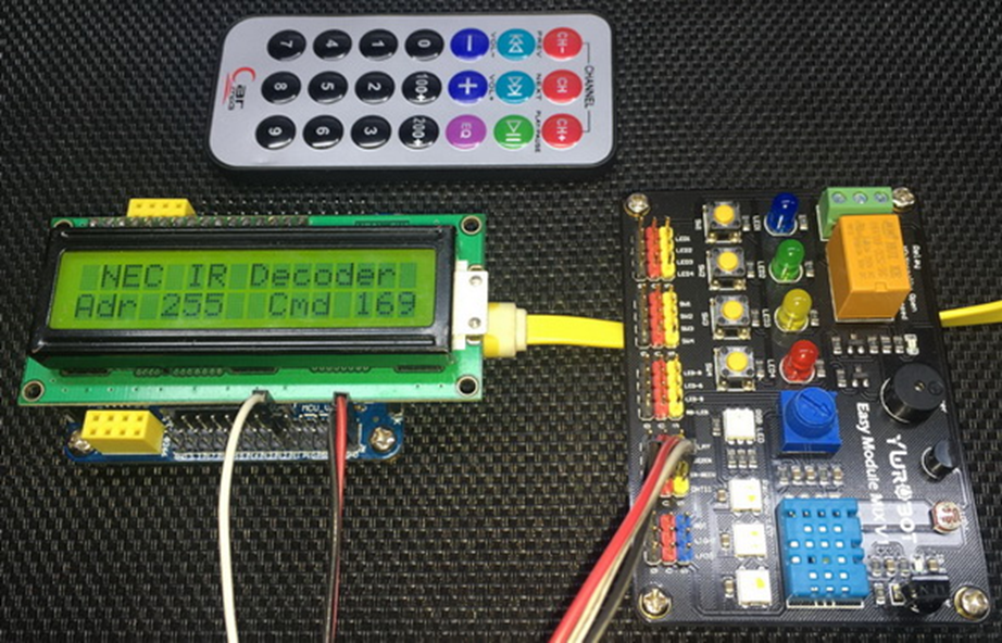
NEC IR Remote Decoding with Timer 0 and External Interrupt
In many projects, we need to control devices remotely, for example a remote-controlled appliance and so it becomes necessary to incorporate some form of remote controller. Infrared (IR) remote controllers are cheap and are widely used as remote controllers in many devices.
Data to be sent from a remote IR transmitter to a receiver is transmitted by modulating it with a carrier wave having frequency between 30kHz to 40kHz. Modulation technique ensures safety from data corruption over long-distance transmissions. An IR receiver at the receiving end picks up and demodulates the sent out modulated data and outputs a stream of pulses. These pulses can vary in terms of pulse widths/timing/position/phase and these variable properties carry the data. Pulse properties are defined by a set of rules called protocol. Decoding the pulses as per protocol help in retrieving information. In most micros, there is no dedicated hardware for decoding IR remote protocols. A micro that needs to decode IR remote data also does not know when it will be receiving an IR burst. Thus, a combination of external interrupt and timer is needed for decoding IR data.
In this segment, we will see how we can use an external interrupt and a timer to easily decode a NEC IR remote. This same method can be applied to any IR remote controller. At this stage, I recommend studying NEC IR protocol from here. SB-Project’s website is an excellent page for IR remote-related info.
Code
 #include "STC8xxx.h"
 #include "BSP.h"
 #include "LCD.c"
 #include "lcd_print.c"

 #define sync_high     5850    //approx 1.3 * 4500us
 #define sync_low      3150    //approx 0.7 * 4500us
 #define one_high      2200    //approx 1.3 * (2250 - 562.5)us
 #define one_low       1180    //approx 0.7 * (2250 - 562.5)us
 #define zero_high     732     //approx 1.3 * (1125 - 562.5)us
 #define zero_low      394     //approx 0.7 * (1125 - 562.5)us

 unsigned char bits = 0x00;
 unsigned char received = 0x00;

 unsigned int frames[33];

 void setup(void);
 void erase_frames(void);
 unsigned char decode(unsigned char start_pos, unsigned char end_pos);
 void decode_NEC(unsigned char *addr, unsigned char *cmd);

 void EXT_0_ISR(void)
 interrupt 0
 {
   frames[bits] = TMR0_get_counter();
   bits++;
   TMR0_start;

   if(bits >= 33)
   {
     received = 1;
     _disable_global_interrupt;
     TMR0_stop;
   }

   TMR0_load_counter_16(0x0000);
 }

 void main(void)
 {
   unsigned char addr = 0x00;
   unsigned char cmd = 0x00;

   setup();

   LCD_goto(1, 0);
   LCD_putstr("NEC IR Decoder");
   LCD_goto(0, 1);
   LCD_putstr("Adr      Cmd");

   while(1)
   {
      if(received != FALSE)
      {
        decode_NEC(&addr, &cmd);

        print_C(3, 1, addr);
        print_C(12, 1, cmd);

        delay_ms(100);

        erase_frames();
        _enable_global_interrupt;
      }
   };
 }

 void setup(void)
 {
   CLK_set_sys_clk(IRC_24M, 2, MCLK_SYSCLK_div_1, MCLK_SYSCLK_no_output);

   erase_frames();

   TMR0_setup(TMR0_16_bit_non_auto_reload, \
              TMR0_sysclk, \
              TMR0_clk_prescalar_12T, \
              TMR0_ext_gate, \
              TMR0_no_clk_out);

   EXT_0_priority_0;
   EXT_0_falling_edge_detection_only;
   _enable_EXT_0_interrupt;
   _enable_global_interrupt;

   LCD_init();
   LCD_clear_home();
 }

 void erase_frames(void)
 {
   for(bits = 0; bits < 33; bits++)
   {
     frames[bits] = 0x0000;
   }

   TMR0_load_counter_16(0x0000);

   received = 0;
   bits = 0;
 }

 unsigned char decode(unsigned char start_pos, unsigned char end_pos)
 {
   unsigned char value = 0;

   for(bits = start_pos; bits <= end_pos; bits++)
   {
     value <<= 1;

     if((frames[bits] >= one_low) && (frames[bits] <= one_high))
     {
       value |= 1;
     }

     else if((frames[bits] >= zero_low) && (frames[bits] <= zero_high))
     {
       value |= 0;
     }

     else if((frames[bits] >= sync_low) && (frames[bits] <= sync_high))
     {
       return 0xFF;
     }
   }

   return value;
 }

 void decode_NEC(unsigned char *addr, unsigned char *cmd)
 {
   *addr = decode(2, 9);
   *cmd = decode(18, 25);
 }
Schematic
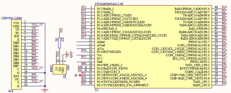
Explanation
A NEC transmission sends out a total of 33 pulses. The first one is a sync pulse and the rest 32 contain address and command info. These 32 address and command bits can be divided into 2 groups. The first 16 bits is one group that contain address and inverted address while the second group of 16-bits contain command and inverted command. The non-inverted signals can be used against the inverted ones for checking data integrity.
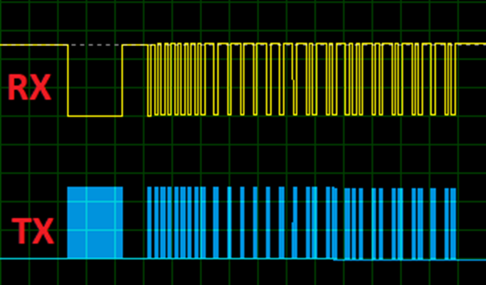
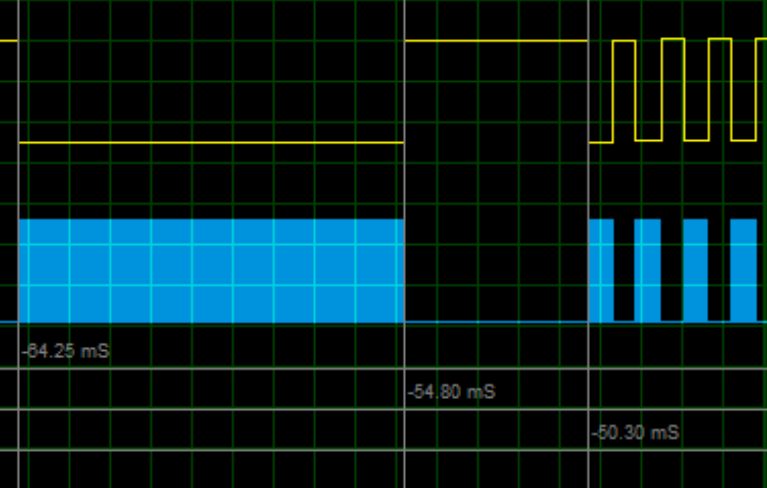
We already know that IR data is received as a steam of pulses. Pulses represent sync bit or ones and zeros. In case of NEC IR protocol, the pulses have variable widths. Sync bit is characterized by a pulse of 9ms high and 4.5ms low – the total pulse time is 13.5ms. Check the timing diagram shown below. Please note that in this timing diagram the blue pulses are from the transmitter and the yellow ones are those received by the receiver. Clearly the pulse streams are inverted. This inversion is done at the IR receiver side.
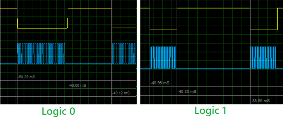
Logic one is represented by a pulse of 560μs high time and 2.25ms of low time – the total pulse time is 2.81ms. Likewise, logic zero is represented by a pulse of 560μs high time and 1.12ms of low time – the total pulse time is 1.68ms.
These timings can vary up to 30% of their ideal values due to a number of factors like medium, temperature, reflections, etc.
Now let’s look at the coding. Firstly, the system clock is set to 12MHz.
CLK_set_sys_clk(IRC_24M, 2, MCLK_SYSCLK_div_1, MCLK_SYSCLK_no_output);
External interrupt is set up to detect falling edges. This is a crucial part in detecting IR pulses because using this interrupt allows us to do other tasks and leave the MCU free for other tasks.
 EXT_0_priority_0;
 EXT_0_falling_edge_detection_only;
 _enable_EXT_0_interrupt;
 _enable_global_interrupt;
Unlike past timer examples, we will need an advanced timer here and so Timer 0 is used. This timer is clocked with the 12MHz system clock that has been divided by a prescalar of 12. Thus, the timer is operating at 1MHz speed, i.e., 1 timer tick = 1µs. We don’t want any output from the timer and so this feature is disabled. The only different thing here that sets this setup apart from the other timer examples is the “gate” feature. Gate tells Timer 0 when and when not to run. There are two possible cases with gating – either the timer runs just like other timers when instructed to run via software or it runs when it is coded to run and INT0 pin is in logic high state. The latter feature is required in this example.
 TMR0_setup(TMR0_16_bit_non_auto_reload, \
            TMR0_sysclk, \
            TMR0_clk_prescalar_12T, \
            TMR0_ext_gate, \
            TMR0_no_clk_out);
Note timer interrupt is not needed.
As soon as there is an external interrupt, the timer immediately stops because of the falling edge that triggered the interrupt and the subsequent low level at INT0 pin. Timer’s count is captured and stored in an array.
 void EXT_0_ISR(void)
 interrupt 0
 {
   frames[bits] = TMR0_get_counter();
   bits++;
   TMR0_start;

   if(bits >= 33)
 1`        {
     received = 1;
     _disable_global_interrupt;
     TMR0_stop;
   }

   TMR0_load_counter_16(0x0000);
 }
The captured counts are compared against maximum and minimum interval limits because as stated, pulse widths may slightly vary from their ideal figures. From captured counts, we can sort pulses and decode pulses. This decoded information can be used to deduce command and address.
 #define sync_high     5850    //approx 1.3 * 4500us
 #define sync_low      3150    //approx 0.7 * 4500us
 #define one_high      2200    //approx 1.3 * (2250 - 562.5)us
 #define one_low       1180    //approx 0.7 * (2250 - 562.5)us
 #define zero_high     732     //approx 1.3 * (1125 - 562.5)us
 #define zero_low      394     //approx 0.7 * (1125 - 562.5)us

 . . . .

 unsigned char decode(unsigned char start_pos, unsigned char end_pos)
 {
   unsigned char value = 0;

   for(bits = start_pos; bits <= end_pos; bits++)
   {
     value <<= 1;

     if((frames[bits] >= one_low) && (frames[bits] <= one_high))
     {
       value |= 1;
     }
     else if((frames[bits] >= zero_low) && (frames[bits] <= zero_high))
     {
       value |= 0;
     }
     else if((frames[bits] >= sync_low) && (frames[bits] <= sync_high))
     {
       return 0xFF;
     }
   }
   return value;
 }
In the main loop, address and command data are displayed on an LCD after receiving and decoding a NEC frame. After that the microcontroller is readied to receive new NEC frame.
 if(received != FALSE)
 {
   decode_NEC(&addr, &cmd);

   print_C(3, 1, addr);
   print_C(12, 1, cmd);
   delay_ms(100);
   erase_frames();
  _enable_global_interrupt;
 }
Demo
|
|
hello.
this is a very good effort to document all and still share with us. thank you very much.
I have one doubt . which programming tool are you using ?
Hi, I am trying to understand the STC15w408as chip, and found this site after weeks of searching for something that sets the output of the GPIO pins to a different state. I have a the 28 pin stc15w and have connected it up with a FTDI board and can write to it using PlatformIO. The thing is, the GPIO ports if just switched on or do a reset they are in the HIGH state and I am trying to make them LOW when you do a reset.
Is your BSP code doing this and for what port or GPIO pin is it setting? I could change your P52 and P55 in your SETUP to the GPIO pins on my development board but not under standing the BSP Code.
Wonder if you get this post? but any help would be gratefully received.
Hi,
How Purchase the development board. Please,give the purchase link for this Development board.
https://www.alibaba.com/product-detail/Development-board-1T-STC8A8K64S4A12-single-chip_62391507065.html
https://world.taobao.com/item/600882463994.htm
https://www.amazon.ca/STC8A8K64S4A12-Development-Controller-Module-Minimal/dp/B08D3Y3R6T
How To read and write string data using IAP into memory
void IAP_erase(unsigned int address)
{
IAP_CONTR = 0x80; //?? IAP
IAP_TPS = 12;
// IAP_CONTR = IAP_WT;
IAP_CMD = IAP_erase_command;
IAP_address(address);
IAP_trigger;
_nop_();
_nop_();
_nop_();
IAP_clear;
}
void IAP_send_string(unsigned int uc_send_addr,unsigned char *uca_send_string,unsigned int uc_number_of_bytes)
{
unsigned int buff_cntr=0;
do
{
IAP_CONTR = 0x80; //?? ISP/IAP ??
IAP_TPS = (unsigned char)(11509200 / 1000000L); //??????
IAP_CMD = IAP_write_command;
// IAP_CMD = IAP_write_command;
IAP_ADDRH = uc_send_addr / 256; //??????(??????????????)
IAP_ADDRL = uc_send_addr % 256; //??????
IAP_DATA = uca_send_string[buff_cntr]; //???? ISP_DATA,????????????
IAP_trigger;//IAP_TRIG();
_nop_();
_nop_();
_nop_();
uc_send_addr++;
// uca_send_string++;
buff_cntr++;
IAP_clear;
delay_ms(8);
}while(–uc_number_of_bytes);
}
void IAP_read_string(unsigned int uc_read_addr,unsigned char *data_read,unsigned int uc_number_of_bytes)
{
unsigned int buff_cntr=0;
do{
IAP_CONTR = 0x80; //?? ISP/IAP ??
IAP_TPS = (unsigned char)(11059200 / 1000000L); //??????
IAP_CMD = IAP_read_command;
// IAP_CMD = IAP_read_command;
IAP_ADDRH = uc_read_addr / 256; //??????(??????????????)
IAP_ADDRL = uc_read_addr % 256; //??????
IAP_trigger;//IAP_TRIG(); //?? 5AH,?? A5H ? ISP/IAP ?????,
//???????
//?? A5H ?, ISP/IAP ?????????
//CPU ?? IAP ???,?????????
_nop_();
_nop_();
_nop_();
data_read[buff_cntr] = IAP_DATA; //???????
uc_read_addr++;
// data_read++;
buff_cntr++;
IAP_clear;
delay_ms(8);
}while(–uc_number_of_bytes);
}
stores only last byte to all bytes of flash memory sector… memory sector selected is 0xF600
Hi, I am using STC MCU since 10 years. Tech support is ZERO. but they are low cost, very stable. Now I have a problem when the chip that I used is obsolete. Now start to use STC8C2K64S4-28I-LQFP32 but no stc8Cxx.h file, I am using stc8Hxx.h file which compiles but in some stage freeze, the existing firmware. With stc8hxx.h file I can compile STC8F2K64S4-28I-LQFP32 and works not bad
.
I wrote them many times for the stc8Cxx.h file never got answer. Where Can I find that file?
Thank you
Give me detail 8f2k64s281MCU read and write programmer
Give me detail 8f2k64s281reed and write programmer distal
Hi. Can you explain how to use I2C in the slave mode ?
I tried STC8G1K08A i2c in slave mode. Doesn’t work (no response). It does not enter interrupt, even on a start condition (everything according to the code in the documentation). I also tried master mode – it works.
Thanks for these tutorials. I’m getting back into STCmicro coding now, having left them alone for the past several years. Back then I only used the STC89C52RC (and C54RD) but this time I’m also using the more powerful STC15 and STC8 types. Your blogs provide a wealth of useful information.
Hello,
You have done great job with all these tutorials. I am an electronics engineer trying to learn some new stuff. I am located in Greece , Europe and I would like to purchase the development board that you are using and download some datasheets in English if possible but I cannot find them anywhere. Could you please help me?
I suggest you buy from AliExpress or similar platform that is available in your country…. You can find the English datasheet here. English documentation can be found in STC’s official websites such as this one….
Thank you very much for your help!!!
i always get excited when you release new tutorials ,you are really doing a great job i wish i could write code and develop libraries like you.
Well, this is very nice and thorough tutorial indeed, many thanks!
Unfortunately I doubt there is good any reason to learn the STC platform beyond curiosity.
The STC 8051, although pretty evolved from the original 8051 ISA, does not offer anything crucial to justify the relatively high price of these micros and development tools along with certain cumbersomeness of this ancient platform.
They simply can not compete even with the legacy Cortex M0 in any way. I am even not aware about any affordable debugger/emulator for them.
All in all, I would never recommend anybody to start learning/using any 8051 without some very good reason to do so.