Exploring STC 8051 Microcontrollers – Coding

|
|
Controlling a DC Motor with Complementary PWM
Complementary PWM is needed in many power system applications like three phase motor control, sine wave inverters, BLDC motor control, etc. STC8A8K64S4A12 fortunately adds features to generate complementary PWMs for the applications aforementioned.

Code
 #include "STC8xxx.h"
 #include "BSP.h"

 #define dead_time_cnt               1
 #define pwm_max_cnt                 400

 #define PB_1                        !P12_get_input
 #define PB_2                        !P13_get_input

 void setup(void);
 void set_PWM_duty(signed int value);

 void main(void)
 {
   signed int duty = 0;

   setup();

   while(1)
   {
       if(PB_1)
       {
           duty += 10;
           delay_ms(100);

           if(duty >= pwm_max_cnt)
           {
             duty = pwm_max_cnt;
           }
       }
       if(PB_2)
       {
           duty -= 10;
           delay_ms(100);

           if(duty <= 0)
           {
             duty = 0;
           }
       }
       if(PB_1 || PB_2)
       {
         set_PWM_duty(duty);
       }
   };
 }

 void setup(void)
 {
   CLK_set_sys_clk(IRC_24M, 2, MCLK_SYSCLK_no_output, MCLK_out_P54);

   P12_input_mode;
   P13_input_mode;

   PWM_clk_set(PWM_clk_sys_PS, PWM_clk_ps_sys_clk_div_1);

   PWM_set_counter(pwm_max_cnt);

   PWM0_setup(PWM_pin_is_PWM_output, \
              PWM_init_lvl_low, \
              PWM_0_pin_P10, \
              PWM_level_normal);

   PWM1_setup(PWM_pin_is_PWM_output, \
              PWM_init_lvl_low, \
              PWM_1_pin_P11, \
              PWM_level_normal);

   PWM_start_counter;
 }

 void set_PWM_duty(signed int value)
 {
   PWM_set_PWM0_T1(value);
   PWM_set_PWM0_T2(0);

   PWM_set_PWM1_T1(pwm_max_cnt - dead_time_cnt);
   PWM_set_PWM1_T2(value + dead_time_cnt);
 }
Schematic
Explanation
Since complementary PWM is a requirement for proper motor drive, the demo here is a rudimentary DC motor drive example with STC’s complementary PWM and a L293 motor driver. The motor’s speed is governed by PWM duty cycle alternation. Pressing buttons assigned with pins P1.2 and P1.3 changes motor speed.
The system clock is set to 12MHz.
CLK_set_sys_clk(IRC_24M, 2, MCLK_SYSCLK_no_output, MCLK_out_P54);
The same clock is used by the enhanced PWM module. Most of the stuffs in the setup are like the previous PWM examples.
 #define dead_time_cnt               1
 #define pwm_max_cnt                 400

 ....

 PWM_clk_set(PWM_clk_sys_PS, PWM_clk_ps_sys_clk_div_1);

 PWM_set_counter(pwm_max_cnt);

 PWM0_setup(PWM_pin_is_PWM_output, \
            PWM_init_lvl_low, \
            PWM_0_pin_P10, \
            PWM_level_normal);

 PWM1_setup(PWM_pin_is_PWM_output, \
            PWM_init_lvl_low, \
            PWM_1_pin_P11, \
            PWM_level_normal);

 PWM_start_counter;
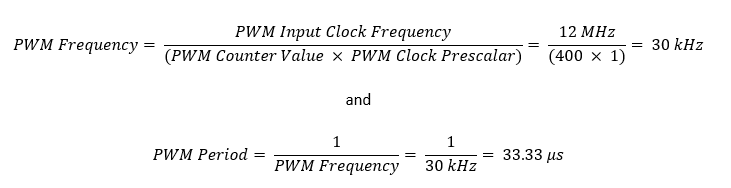
The math behind PWM generation is same as the ones we have already seen:
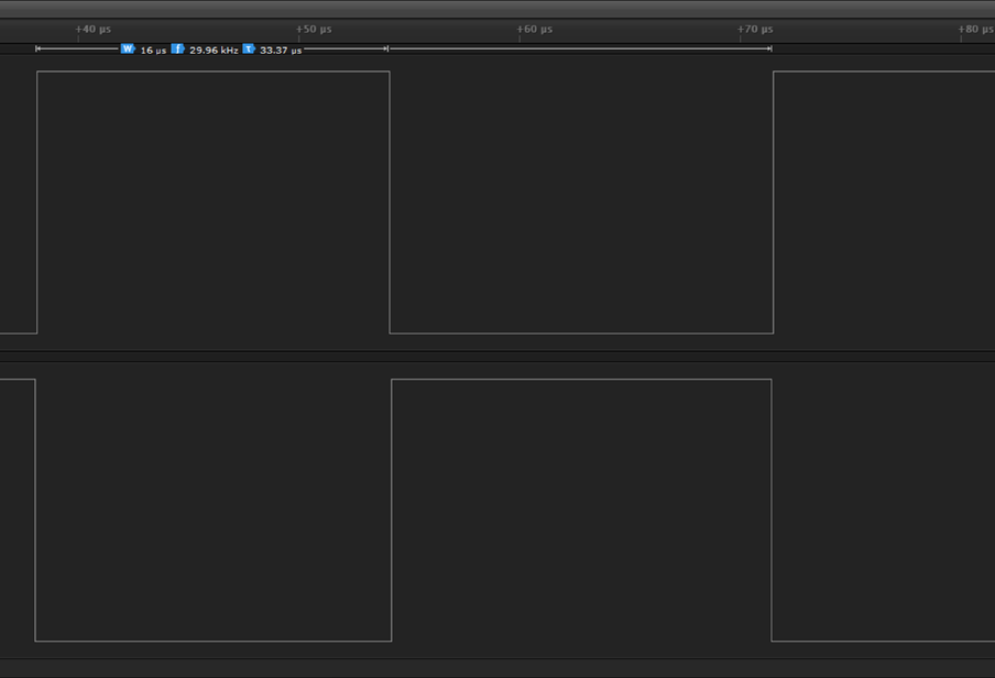
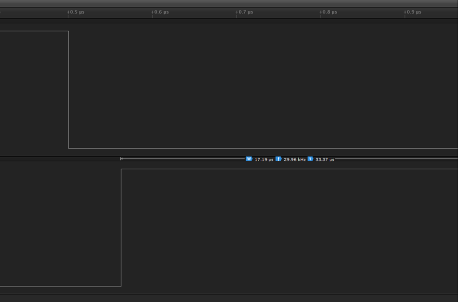
The logic analyser data proves that the above figures are correct:
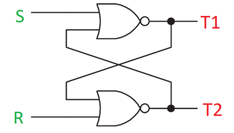
Now imagine a SR flip-flop with outputs T1 and T2. So far, we have seen that varying T1 and T2 alter PWM duty cycle. Thus, S and R can be imagined as logic transition counts. When the PWM counter reaches up to these values, high-to-low or low-to-high transition occurs in the PWM waveform.
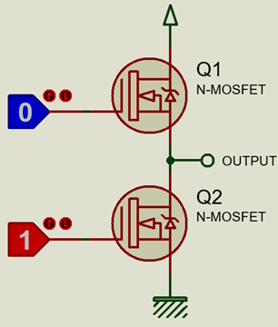
To generate complementary PWM, we would need two PWM channels and so in this example PWM channels 0 and 1 are selected. The word “complementary” suggests that two things are opposite of the other and so in such PWM technique, there are two PWMs that have opposite logic polarities. This is the simplistic presentation of complementary PWM.
In ideal terms, if one PWM channel is running with 40% duty cycle, the other should be running at 60% (-40%) duty cycle. However, doing so practically would lead to some issues because when one PWM is going from high-to-low transition, the other is doing just the opposite and during these transition times at some point both PWMs are at same logic level. If these PWMs are fed to external devices like transistors or MOSFETs as shown below then quite possibly during the transition times both MOSFETs would be momentarily turn on, leading to temporary short-circuit and unnecessary overheating. The temporal short circuit may even cause the external devices to get damaged or cause momentary power shortages. To avoid this phenomenon, we have to apply dead-time technique to ensure that the transitions occur separately with some minute delay.
Now let’s see how the PWM duty cycle is ensured while maintaining the needs so far discussed. The following code snippet is responsible for maintaining PWM duty cycles in complementary format. It may look confusing unlike the previous examples.
 #define dead_time_cnt               1
 #define pwm_max_cnt                 400

 ....

 void set_PWM_duty(signed int value)
 {
   PWM_set_PWM0_T1(value);
   PWM_set_PWM0_T2(0);

   PWM_set_PWM1_T1(pwm_max_cnt - dead_time_cnt);
   PWM_set_PWM1_T2(value + dead_time_cnt);
 }
The confusion will vanish after carefully looking at the math below. Imagine that we want to set the duty cycle to 75%.
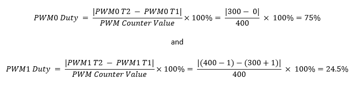
As the math shows due to the application of dead-time, PWM1’s duty cycle is slightly less than the ideal 25% mark. In this example, 1 count of dead time is equivalent to 0.25% duty cycle and since there are two such counts the total duty cycle is reduced by 0.5%.
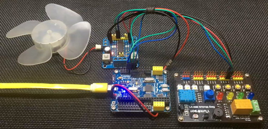
Demo
|
|
hello.
this is a very good effort to document all and still share with us. thank you very much.
I have one doubt . which programming tool are you using ?
Hi, I am trying to understand the STC15w408as chip, and found this site after weeks of searching for something that sets the output of the GPIO pins to a different state. I have a the 28 pin stc15w and have connected it up with a FTDI board and can write to it using PlatformIO. The thing is, the GPIO ports if just switched on or do a reset they are in the HIGH state and I am trying to make them LOW when you do a reset.
Is your BSP code doing this and for what port or GPIO pin is it setting? I could change your P52 and P55 in your SETUP to the GPIO pins on my development board but not under standing the BSP Code.
Wonder if you get this post? but any help would be gratefully received.
Hi,
How Purchase the development board. Please,give the purchase link for this Development board.
https://www.alibaba.com/product-detail/Development-board-1T-STC8A8K64S4A12-single-chip_62391507065.html
https://world.taobao.com/item/600882463994.htm
https://www.amazon.ca/STC8A8K64S4A12-Development-Controller-Module-Minimal/dp/B08D3Y3R6T
How To read and write string data using IAP into memory
void IAP_erase(unsigned int address)
{
IAP_CONTR = 0x80; //?? IAP
IAP_TPS = 12;
// IAP_CONTR = IAP_WT;
IAP_CMD = IAP_erase_command;
IAP_address(address);
IAP_trigger;
_nop_();
_nop_();
_nop_();
IAP_clear;
}
void IAP_send_string(unsigned int uc_send_addr,unsigned char *uca_send_string,unsigned int uc_number_of_bytes)
{
unsigned int buff_cntr=0;
do
{
IAP_CONTR = 0x80; //?? ISP/IAP ??
IAP_TPS = (unsigned char)(11509200 / 1000000L); //??????
IAP_CMD = IAP_write_command;
// IAP_CMD = IAP_write_command;
IAP_ADDRH = uc_send_addr / 256; //??????(??????????????)
IAP_ADDRL = uc_send_addr % 256; //??????
IAP_DATA = uca_send_string[buff_cntr]; //???? ISP_DATA,????????????
IAP_trigger;//IAP_TRIG();
_nop_();
_nop_();
_nop_();
uc_send_addr++;
// uca_send_string++;
buff_cntr++;
IAP_clear;
delay_ms(8);
}while(–uc_number_of_bytes);
}
void IAP_read_string(unsigned int uc_read_addr,unsigned char *data_read,unsigned int uc_number_of_bytes)
{
unsigned int buff_cntr=0;
do{
IAP_CONTR = 0x80; //?? ISP/IAP ??
IAP_TPS = (unsigned char)(11059200 / 1000000L); //??????
IAP_CMD = IAP_read_command;
// IAP_CMD = IAP_read_command;
IAP_ADDRH = uc_read_addr / 256; //??????(??????????????)
IAP_ADDRL = uc_read_addr % 256; //??????
IAP_trigger;//IAP_TRIG(); //?? 5AH,?? A5H ? ISP/IAP ?????,
//???????
//?? A5H ?, ISP/IAP ?????????
//CPU ?? IAP ???,?????????
_nop_();
_nop_();
_nop_();
data_read[buff_cntr] = IAP_DATA; //???????
uc_read_addr++;
// data_read++;
buff_cntr++;
IAP_clear;
delay_ms(8);
}while(–uc_number_of_bytes);
}
stores only last byte to all bytes of flash memory sector… memory sector selected is 0xF600
Hi, I am using STC MCU since 10 years. Tech support is ZERO. but they are low cost, very stable. Now I have a problem when the chip that I used is obsolete. Now start to use STC8C2K64S4-28I-LQFP32 but no stc8Cxx.h file, I am using stc8Hxx.h file which compiles but in some stage freeze, the existing firmware. With stc8hxx.h file I can compile STC8F2K64S4-28I-LQFP32 and works not bad
.
I wrote them many times for the stc8Cxx.h file never got answer. Where Can I find that file?
Thank you
Give me detail 8f2k64s281MCU read and write programmer
Give me detail 8f2k64s281reed and write programmer distal
Hi. Can you explain how to use I2C in the slave mode ?
I tried STC8G1K08A i2c in slave mode. Doesn’t work (no response). It does not enter interrupt, even on a start condition (everything according to the code in the documentation). I also tried master mode – it works.
Thanks for these tutorials. I’m getting back into STCmicro coding now, having left them alone for the past several years. Back then I only used the STC89C52RC (and C54RD) but this time I’m also using the more powerful STC15 and STC8 types. Your blogs provide a wealth of useful information.
Hello,
You have done great job with all these tutorials. I am an electronics engineer trying to learn some new stuff. I am located in Greece , Europe and I would like to purchase the development board that you are using and download some datasheets in English if possible but I cannot find them anywhere. Could you please help me?
I suggest you buy from AliExpress or similar platform that is available in your country…. You can find the English datasheet here. English documentation can be found in STC’s official websites such as this one….
Thank you very much for your help!!!
i always get excited when you release new tutorials ,you are really doing a great job i wish i could write code and develop libraries like you.
Well, this is very nice and thorough tutorial indeed, many thanks!
Unfortunately I doubt there is good any reason to learn the STC platform beyond curiosity.
The STC 8051, although pretty evolved from the original 8051 ISA, does not offer anything crucial to justify the relatively high price of these micros and development tools along with certain cumbersomeness of this ancient platform.
They simply can not compete even with the legacy Cortex M0 in any way. I am even not aware about any affordable debugger/emulator for them.
All in all, I would never recommend anybody to start learning/using any 8051 without some very good reason to do so.