Exploring STC 8051 Microcontrollers – Coding

|
|
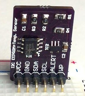
IAP/EEPROM
Storing calibration, configuration, setting data and some preset values are required in some devices and so they need to be stored in memories that can be later modified if needed or else left alone. For such cases, we would need either EEPROM or flash memories. Like many modern microcontrollers, STC microcontrollers don’t come equipped with built-in EEPROM memory but through coding we can store aforementioned data in internal flash memory through IAP/ISP technology.
Of course, there are ways to use external EEPROM and flash memories like AT24Cxx EERPOMS and W25X16 but that would require external wiring and the use of communication pins. Having flash/EEPROM memory embedded in the application chip allows us to simply avoid these and have our microcontroller ready for fast deployment.
In this section, we would see how to use internal flash to store data.
Code
 # include "STC8xxx.h"
 #include "BSP.h"
 #include "LCD.c"
 #include "lcd_print.c"

 #define BASE_ADDRESS  0x0400

 void setup(void);

 void main(void)
 {
   unsigned char i = 0;
   setup();

   LCD_goto(0, 0);
   LCD_putstr("R Addr:");
   LCD_goto(0, 1);
   LCD_putstr("R Data:");

   i = IAP_read(BASE_ADDRESS);
   delay_ms(10);
   print_I(11, 0, BASE_ADDRESS);
   print_C(14, 1, i);

   delay_ms(2000);

   if(i == 0)
   {
     LCD_clear_home();
     LCD_goto(0, 0);
     LCD_putstr("Performing Erase");
     LCD_goto(0, 1);
     LCD_putstr("....");
     IAP_erase(BASE_ADDRESS);
     delay_ms(1000);
   }

   LCD_clear_home();
   delay_ms(100);

   LCD_goto(0, 0);
   LCD_putstr("W Addr:");
   LCD_goto(0, 1);
   LCD_putstr("W Data:");

   i = (P1 & 0x03);
   IAP_write(BASE_ADDRESS, i);
   print_I(11, 0, BASE_ADDRESS);
   print_C(14, 1, i);
   delay_ms(2000);

   LCD_clear_home();
   delay_ms(100);

   LCD_goto(0, 0);
   LCD_putstr("R Addr:");
   LCD_goto(0, 1);
   LCD_putstr("R Data:");

   i = IAP_read(BASE_ADDRESS);
   delay_ms(10);
   print_I(11, 0, BASE_ADDRESS);
   print_C(14, 1, i);

   delay_ms(2000);

   while(1)
   {
   };
 }


 void setup(void)
 {
   CLK_set_sys_clk(IRC_24M, 2, MCLK_SYSCLK_div_1, MCLK_out_P54);

   P10_input_mode;
   P11_input_mode;

   LCD_init();
   LCD_clear_home();
 }
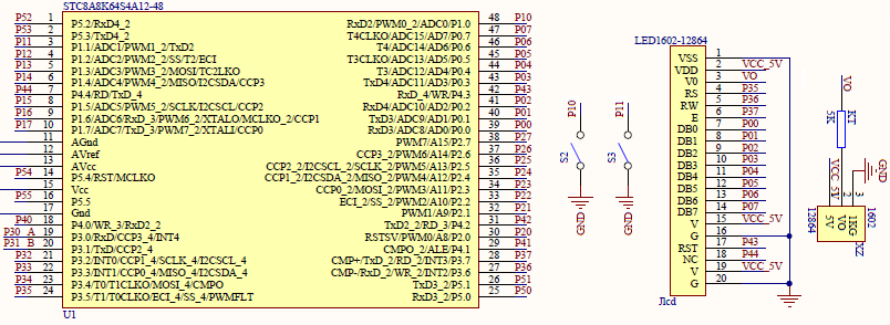
Schematic
Explanation
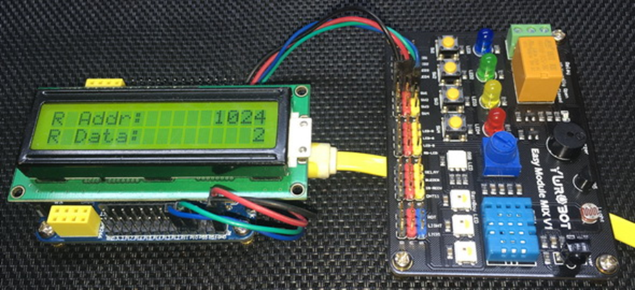
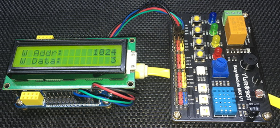
The code in this rudimentary demo works by reading a single fixed location of internal flash, here 0x0400. An LCD display is used to show the read location and its content. If the content is 0 then an erase is performed because it is assumed to be empty. After performing erase, the same location is written. The write value is generated by reading the logic states of the lowermost bits (i.e., bit 0 and 1) of P1 port. After writing, the location is read again as to check if the data is properly saved. If the micro is reset or if there is a power-down, the saved data is retained, confirming that indeed data has been preserved in the internal flash memory.
IAP functionality utilizes the following three functions. As can be seen that these functions must follow a sequence operation in order to enable access to internal flash.
 unsigned char IAP_read(unsigned int address)
 {
   unsigned char value = 0x00;

   IAP_CONTR = IAP_WT;
   IAP_CMD = IAP_read_command;
   IAP_address(address);
   IAP_trigger;
   _nop_();
   value = IAP_DATA;
   IAP_clear;

   return value;
 }

 void IAP_write(unsigned int address, unsigned char value)
 {
   IAP_CONTR = IAP_WT;
   IAP_CMD = IAP_write_command;
   IAP_address(address);
   IAP_DATA = value;
   IAP_trigger;
   _nop_();
   IAP_clear;
 }

 void IAP_erase(unsigned int address)
 {
   IAP_CONTR = IAP_WT;
   IAP_CMD = IAP_erase_command;
   IAP_address(address);
   IAP_trigger;
   _nop_();
   IAP_clear;
 }
Some key points to note while using internal flash as EEPROM:
- The flash memory of STC micro can be divided into sectors of 512 bytes.
- Byte write or byte erase operations are not possible as these are done at sector level. This means that to change one byte of a sector, we would have to totally erase and write that sector.
- Basing on point 2, it is better to use two sectors for one set of data. We can, then, maintain wear-leveling and memory ring buffer.
- We must use those locations of internal flash that won’t have any part of application code. As with other microcontrollers, STC micros begin executing code from 0x0000 location of memory. Thus, it is better to use locations at the last portion of internal flash memory.
- Flash memory has an endurance of 100,000 cycles. Thus, frequent writes/erases must be avoided. It is better to use a RAM buffer for applications that require frequent data storage. By using such a technique, flash memory is only modified before a reset or power down event. This is just like saving all your files before shutting down your PC. Most modern solid-state drives (SSD) come with a DRAM cache and this has almost similar usage.
- IAP size can be set by using STC programmer GUI.
Demo
|
|
hello.
this is a very good effort to document all and still share with us. thank you very much.
I have one doubt . which programming tool are you using ?
Hi, I am trying to understand the STC15w408as chip, and found this site after weeks of searching for something that sets the output of the GPIO pins to a different state. I have a the 28 pin stc15w and have connected it up with a FTDI board and can write to it using PlatformIO. The thing is, the GPIO ports if just switched on or do a reset they are in the HIGH state and I am trying to make them LOW when you do a reset.
Is your BSP code doing this and for what port or GPIO pin is it setting? I could change your P52 and P55 in your SETUP to the GPIO pins on my development board but not under standing the BSP Code.
Wonder if you get this post? but any help would be gratefully received.
Hi,
How Purchase the development board. Please,give the purchase link for this Development board.
https://www.alibaba.com/product-detail/Development-board-1T-STC8A8K64S4A12-single-chip_62391507065.html
https://world.taobao.com/item/600882463994.htm
https://www.amazon.ca/STC8A8K64S4A12-Development-Controller-Module-Minimal/dp/B08D3Y3R6T
How To read and write string data using IAP into memory
void IAP_erase(unsigned int address)
{
IAP_CONTR = 0x80; //?? IAP
IAP_TPS = 12;
// IAP_CONTR = IAP_WT;
IAP_CMD = IAP_erase_command;
IAP_address(address);
IAP_trigger;
_nop_();
_nop_();
_nop_();
IAP_clear;
}
void IAP_send_string(unsigned int uc_send_addr,unsigned char *uca_send_string,unsigned int uc_number_of_bytes)
{
unsigned int buff_cntr=0;
do
{
IAP_CONTR = 0x80; //?? ISP/IAP ??
IAP_TPS = (unsigned char)(11509200 / 1000000L); //??????
IAP_CMD = IAP_write_command;
// IAP_CMD = IAP_write_command;
IAP_ADDRH = uc_send_addr / 256; //??????(??????????????)
IAP_ADDRL = uc_send_addr % 256; //??????
IAP_DATA = uca_send_string[buff_cntr]; //???? ISP_DATA,????????????
IAP_trigger;//IAP_TRIG();
_nop_();
_nop_();
_nop_();
uc_send_addr++;
// uca_send_string++;
buff_cntr++;
IAP_clear;
delay_ms(8);
}while(–uc_number_of_bytes);
}
void IAP_read_string(unsigned int uc_read_addr,unsigned char *data_read,unsigned int uc_number_of_bytes)
{
unsigned int buff_cntr=0;
do{
IAP_CONTR = 0x80; //?? ISP/IAP ??
IAP_TPS = (unsigned char)(11059200 / 1000000L); //??????
IAP_CMD = IAP_read_command;
// IAP_CMD = IAP_read_command;
IAP_ADDRH = uc_read_addr / 256; //??????(??????????????)
IAP_ADDRL = uc_read_addr % 256; //??????
IAP_trigger;//IAP_TRIG(); //?? 5AH,?? A5H ? ISP/IAP ?????,
//???????
//?? A5H ?, ISP/IAP ?????????
//CPU ?? IAP ???,?????????
_nop_();
_nop_();
_nop_();
data_read[buff_cntr] = IAP_DATA; //???????
uc_read_addr++;
// data_read++;
buff_cntr++;
IAP_clear;
delay_ms(8);
}while(–uc_number_of_bytes);
}
stores only last byte to all bytes of flash memory sector… memory sector selected is 0xF600
Hi, I am using STC MCU since 10 years. Tech support is ZERO. but they are low cost, very stable. Now I have a problem when the chip that I used is obsolete. Now start to use STC8C2K64S4-28I-LQFP32 but no stc8Cxx.h file, I am using stc8Hxx.h file which compiles but in some stage freeze, the existing firmware. With stc8hxx.h file I can compile STC8F2K64S4-28I-LQFP32 and works not bad
.
I wrote them many times for the stc8Cxx.h file never got answer. Where Can I find that file?
Thank you
Give me detail 8f2k64s281MCU read and write programmer
Give me detail 8f2k64s281reed and write programmer distal
Hi. Can you explain how to use I2C in the slave mode ?
I tried STC8G1K08A i2c in slave mode. Doesn’t work (no response). It does not enter interrupt, even on a start condition (everything according to the code in the documentation). I also tried master mode – it works.
Thanks for these tutorials. I’m getting back into STCmicro coding now, having left them alone for the past several years. Back then I only used the STC89C52RC (and C54RD) but this time I’m also using the more powerful STC15 and STC8 types. Your blogs provide a wealth of useful information.
Hello,
You have done great job with all these tutorials. I am an electronics engineer trying to learn some new stuff. I am located in Greece , Europe and I would like to purchase the development board that you are using and download some datasheets in English if possible but I cannot find them anywhere. Could you please help me?
I suggest you buy from AliExpress or similar platform that is available in your country…. You can find the English datasheet here. English documentation can be found in STC’s official websites such as this one….
Thank you very much for your help!!!
i always get excited when you release new tutorials ,you are really doing a great job i wish i could write code and develop libraries like you.
Well, this is very nice and thorough tutorial indeed, many thanks!
Unfortunately I doubt there is good any reason to learn the STC platform beyond curiosity.
The STC 8051, although pretty evolved from the original 8051 ISA, does not offer anything crucial to justify the relatively high price of these micros and development tools along with certain cumbersomeness of this ancient platform.
They simply can not compete even with the legacy Cortex M0 in any way. I am even not aware about any affordable debugger/emulator for them.
All in all, I would never recommend anybody to start learning/using any 8051 without some very good reason to do so.