Exploring STC 8051 Microcontrollers – Coding

|
|
Using PCA as a High-Speed Pulse Generator
In many cases, we need to generate high-frequency carrier waveform or pulse trains. For example, this is needed when we need to make an infrared (IR) remote transmitter. This job can easily be done by using a timer or software delays. However, in STC micros, we have PCA hardware to accomplish the same job much more easily. This lets us use general purpose timers for other tasks.
Code
#include "STC8xxx.h"
#include "BSP.h"
#define freq_change (12000000L / 2 / 38400)
unsigned int value = freq_change;
void setup(void);
void PCA_ISR(void)
interrupt 7
{
clear_PCA_0_flag;
PCA0_load_value(value);
value += freq_change;
}
void main(void)
{
setup();
while(1)
{
if(P52_get_input == FALSE)
{
P24_high;
P55_low;
}
else
{
P24_low;
P55_high;
}
};
}
void setup(void)
{
CLK_set_sys_clk(IRC_24M, 2, MCLK_SYSCLK_no_output, MCLK_out_P54);
P01_push_pull_mode;
P55_open_drain_mode;
P52_input_mode;
P52_pull_up_enable;
PCA_pin_option(0x10);
PCA_setup(PCA_continue_counting_in_idle_mode, PCA_clk_sys_clk_div_1);
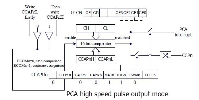
PCA_0_mode(PCA_16_bit_high_speed_pulse_output);
PCA_load_counter(0);
PCA0_load_value(value);
_enable_PCA_0_interrupt;
_enable_global_interrupt;
PCA_start_counter;
}
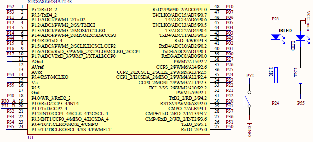
Schematic
Explanation
In this example, PCA high-speed pulse mode is used to make an IR remote transmitter.
Since PCA is a time-dependent hardware peripheral, we need to be sure of the system clock settings. As with most examples, the system clock is set to 12MHz
CLK_set_sys_clk(IRC_24M, 2, MCLK_SYSCLK_no_output, MCLK_out_P54);
Four GPIO pins are required for this example and are set right after selecting the system clock. A button is connected with pin P5.2. Pressing the button would change the logic state of both the onboard LED (P5.5) and pin P2.4. Lastly, pin P2.3 is set as the PCA CCP0 pin. This pin is the high-speed pulse output pin. P2.3 and P2.4 are connected to an IR LED.
Note that P2.4 is not set like other GPIOs because it is already set by PCA hardware.
 P01_push_pull_mode;
 P55_open_drain_mode;

 P52_input_mode;
 P52_pull_up_enable;

 PCA_pin_option(0x10);
Now let’s see how the PCA hardware is set. Firstly, the PCA clock and counting mode are set. PCA clock is set to run at 12MHz, i.e., at system clock speed. Next, the PCA channel to be used and its mode of operation is set, here – 16-bit high speed pulse output mode. The PCA counter is set 0 count and PCA0 channel is loaded with a count value.
 PCA_setup(PCA_continue_counting_in_idle_mode, PCA_clk_sys_clk_div_1);

 PCA_0_mode(PCA_16_bit_high_speed_pulse_output);

 PCA_load_counter(0);
 PCA0_load_value(value);

 _enable_PCA_0_interrupt;
 _enable_global_interrupt;

 PCA_start_counter;
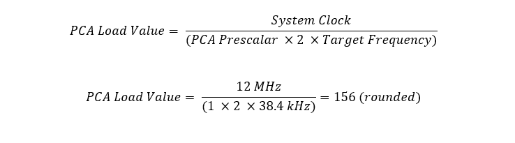
The loaded value is the count value required to generate the desired frequency of 38.4kHz (26µs period).
Finally, the PCA0 and global interrupts are enabled before starting the PCA counter.
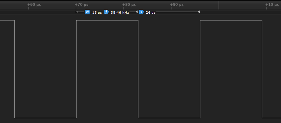
Note that PCA counter keeps counting and is not reloaded anywhere in the whole code. It is left on its own and it will rollover after 65535 counts. When the PCA counter counts to 156 counts, PCA0 interrupt is triggered. Note that 156 counts equal 13µs because the PCA clock is running at 12MHz. On each interrupt, PCA0’s channel polarity is altered. This means 13µs is the pulse width of high-speed pulse output waveform.

PCA interrupt is processed by clearing PCA0 interrupt flag and by loading PCA0 with a new count value (previous count + load value, i.e., 156 + 156 = 312) because after that new count (312) PCA0 interrupt will be triggered again and the process repeats over and over again.
 void PCA_ISR(void)
 interrupt 7
 {
   clear_PCA_0_flag;
   PCA0_load_value(value);
   value += freq_change;
 }
Inside the main loop, the push button pin is polled. If the button is pressed, the IR LED is enabled by setting P2.4 high or else it is disabled. Since P2.3 is the PCA 0 output, there is always 38.4 kHz square pulses present in that pin. Only when P2.4 is set is high, the IR LED lights up. It is just like a simple AND logic.
if(P52_get_input == FALSE)
 {
   P24_high;
   P55_low;
 }
 else
 {
   P24_low;
   P55_high;
 }
Demo
|
|
hello.
this is a very good effort to document all and still share with us. thank you very much.
I have one doubt . which programming tool are you using ?
Hi, I am trying to understand the STC15w408as chip, and found this site after weeks of searching for something that sets the output of the GPIO pins to a different state. I have a the 28 pin stc15w and have connected it up with a FTDI board and can write to it using PlatformIO. The thing is, the GPIO ports if just switched on or do a reset they are in the HIGH state and I am trying to make them LOW when you do a reset.
Is your BSP code doing this and for what port or GPIO pin is it setting? I could change your P52 and P55 in your SETUP to the GPIO pins on my development board but not under standing the BSP Code.
Wonder if you get this post? but any help would be gratefully received.
Hi,
How Purchase the development board. Please,give the purchase link for this Development board.
https://www.alibaba.com/product-detail/Development-board-1T-STC8A8K64S4A12-single-chip_62391507065.html
https://world.taobao.com/item/600882463994.htm
https://www.amazon.ca/STC8A8K64S4A12-Development-Controller-Module-Minimal/dp/B08D3Y3R6T
How To read and write string data using IAP into memory
void IAP_erase(unsigned int address)
{
IAP_CONTR = 0x80; //?? IAP
IAP_TPS = 12;
// IAP_CONTR = IAP_WT;
IAP_CMD = IAP_erase_command;
IAP_address(address);
IAP_trigger;
_nop_();
_nop_();
_nop_();
IAP_clear;
}
void IAP_send_string(unsigned int uc_send_addr,unsigned char *uca_send_string,unsigned int uc_number_of_bytes)
{
unsigned int buff_cntr=0;
do
{
IAP_CONTR = 0x80; //?? ISP/IAP ??
IAP_TPS = (unsigned char)(11509200 / 1000000L); //??????
IAP_CMD = IAP_write_command;
// IAP_CMD = IAP_write_command;
IAP_ADDRH = uc_send_addr / 256; //??????(??????????????)
IAP_ADDRL = uc_send_addr % 256; //??????
IAP_DATA = uca_send_string[buff_cntr]; //???? ISP_DATA,????????????
IAP_trigger;//IAP_TRIG();
_nop_();
_nop_();
_nop_();
uc_send_addr++;
// uca_send_string++;
buff_cntr++;
IAP_clear;
delay_ms(8);
}while(–uc_number_of_bytes);
}
void IAP_read_string(unsigned int uc_read_addr,unsigned char *data_read,unsigned int uc_number_of_bytes)
{
unsigned int buff_cntr=0;
do{
IAP_CONTR = 0x80; //?? ISP/IAP ??
IAP_TPS = (unsigned char)(11059200 / 1000000L); //??????
IAP_CMD = IAP_read_command;
// IAP_CMD = IAP_read_command;
IAP_ADDRH = uc_read_addr / 256; //??????(??????????????)
IAP_ADDRL = uc_read_addr % 256; //??????
IAP_trigger;//IAP_TRIG(); //?? 5AH,?? A5H ? ISP/IAP ?????,
//???????
//?? A5H ?, ISP/IAP ?????????
//CPU ?? IAP ???,?????????
_nop_();
_nop_();
_nop_();
data_read[buff_cntr] = IAP_DATA; //???????
uc_read_addr++;
// data_read++;
buff_cntr++;
IAP_clear;
delay_ms(8);
}while(–uc_number_of_bytes);
}
stores only last byte to all bytes of flash memory sector… memory sector selected is 0xF600
Hi, I am using STC MCU since 10 years. Tech support is ZERO. but they are low cost, very stable. Now I have a problem when the chip that I used is obsolete. Now start to use STC8C2K64S4-28I-LQFP32 but no stc8Cxx.h file, I am using stc8Hxx.h file which compiles but in some stage freeze, the existing firmware. With stc8hxx.h file I can compile STC8F2K64S4-28I-LQFP32 and works not bad
.
I wrote them many times for the stc8Cxx.h file never got answer. Where Can I find that file?
Thank you
Give me detail 8f2k64s281MCU read and write programmer
Give me detail 8f2k64s281reed and write programmer distal
Hi. Can you explain how to use I2C in the slave mode ?
I tried STC8G1K08A i2c in slave mode. Doesn’t work (no response). It does not enter interrupt, even on a start condition (everything according to the code in the documentation). I also tried master mode – it works.
Thanks for these tutorials. I’m getting back into STCmicro coding now, having left them alone for the past several years. Back then I only used the STC89C52RC (and C54RD) but this time I’m also using the more powerful STC15 and STC8 types. Your blogs provide a wealth of useful information.
Hello,
You have done great job with all these tutorials. I am an electronics engineer trying to learn some new stuff. I am located in Greece , Europe and I would like to purchase the development board that you are using and download some datasheets in English if possible but I cannot find them anywhere. Could you please help me?
I suggest you buy from AliExpress or similar platform that is available in your country…. You can find the English datasheet here. English documentation can be found in STC’s official websites such as this one….
Thank you very much for your help!!!
i always get excited when you release new tutorials ,you are really doing a great job i wish i could write code and develop libraries like you.
Well, this is very nice and thorough tutorial indeed, many thanks!
Unfortunately I doubt there is good any reason to learn the STC platform beyond curiosity.
The STC 8051, although pretty evolved from the original 8051 ISA, does not offer anything crucial to justify the relatively high price of these micros and development tools along with certain cumbersomeness of this ancient platform.
They simply can not compete even with the legacy Cortex M0 in any way. I am even not aware about any affordable debugger/emulator for them.
All in all, I would never recommend anybody to start learning/using any 8051 without some very good reason to do so.