Exploring STC 8051 Microcontrollers – Coding

|
|
Using PCA to Measure Frequency
Frequency measurement is often a challenging task as it requires good understanding of timers and input capture modules. Frequency measurement becomes very important while designing power electronics devices like generator controllers, inverters, power line measurement meters, etc. In STC8A8K64S4A12, there is no dedicated input capture hardware module but there is a PCA module that can be used to replenish this absence of a dedicated input capture peripheral.
Code
 #include "STC8xxx.h"
 #include "BSP.h"
 #include "LCD.c"
 #include "lcd_print.c"

 unsigned int first_edge = 0x0000;
 unsigned int second_edge = 0x0000;

 unsigned long clks = 0x00000000;
 unsigned long ov_cnt = 0x00000000;

 void setup(void);

 void PCA_ISR(void)
 interrupt 7
 {
     if(check_PCA_Counter_overflow_flag)
     {
       ov_cnt++;;
       clear_PCA_Counter_overflow_flag;
     }

     if(check_PCA_0_flag)
     {
       second_edge = PCA_get_CCAP0();
       clks = ((65536 * ov_cnt) + second_edge - first_edge);
       ov_cnt = 0;
       first_edge = second_edge;
       second_edge = 0;
       clear_PCA_0_flag;
     }
 }

 void main(void)
 {
   float f = 0.0;

   unsigned char s = 0;

   setup();

   LCD_goto(0, 0);
   LCD_putstr("Period/ms:");

   LCD_goto(0, 1);
   LCD_putstr("Freq./kHz:");

   while(1)
   {
     PWM_stop_counter;

     switch(s)
     {
       case 1:
       {
         PWM_clk_set(PWM_clk_sys_PS, PWM_clk_ps_sys_clk_div_1);
         break;
       }

       case 2:
       {
         PWM_clk_set(PWM_clk_sys_PS, PWM_clk_ps_sys_clk_div_4);
         break;
       }

       case 3:
       {
         PWM_clk_set(PWM_clk_sys_PS, PWM_clk_ps_sys_clk_div_3);
         break;
       }

       default:
       {
         PWM_clk_set(PWM_clk_sys_PS, PWM_clk_ps_sys_clk_div_2);
         break;
       }
 }

     PWM_start_counter;
     delay_ms(1000);

     f = (12000.0 / ((float)clks));
     print_I(11, 0, clks);
     print_F(11, 1, f, 1);

     delay_ms(1000);

     s++;
     if(s > 3)
     {
       s = 0;
     }
   };
 }

 void setup(void)
 {
   CLK_set_sys_clk(IRC_24M, 2, MCLK_SYSCLK_no_output, MCLK_out_P54);

   PWM0_setup(PWM_pin_is_PWM_output, \
                    PWM_init_lvl_low, \
                    PWM_0_pin_P10, \
                    PWM_level_normal);

   PWM_clk_set(PWM_clk_sys_PS, PWM_clk_ps_sys_clk_div_2);
   PWM_set_counter(500);

   PWM_set_PWM0_T1(0);
   PWM_set_PWM0_T2(200);

   PWM_start_counter;

   PCA_pin_option(0x00);

   PCA_setup(PCA_continue_counting_in_idle_mode, PCA_clk_sys_clk_div_1);
   PCA_load_counter(0x0000);

   PCA_0_mode(PCA_16_bit_falling_edge_capture);

   _enable_PCA_0_interrupt;
   _enable_PCA_counter_interrupt;
   _enable_global_interrupt;

   PCA_start_counter;

   LCD_init();
   LCD_clear_home();
 }
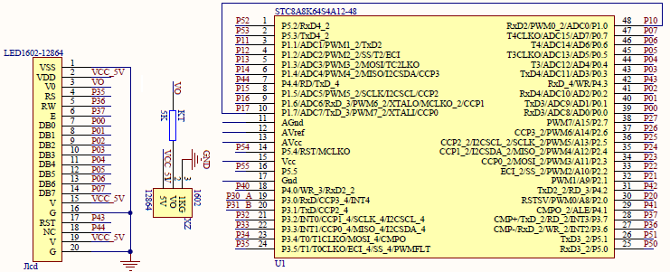
Schematic
Explanation
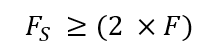
Measurement of frequency can easily be done by timing the time difference between two successive rising or falling edge captures. Input capture hardware along with a timer would scan and sample incoming waveform. Thus, input capture hardware must have at least twice the sampling frequency than the frequency of the waveform coming to the capture input. This is simply the Nyquist criterion.
To demonstrate frequency measurement with PCA, I have used two hardware. Firstly, I used a PWM generator to generate waveform of different frequencies and secondly, a PCA module to capture the PWM waveform.
To begin with, note that the micro is running at 12MHz.
CLK_set_sys_clk(IRC_24M, 2, MCLK_SYSCLK_no_output, MCLK_out_P54);
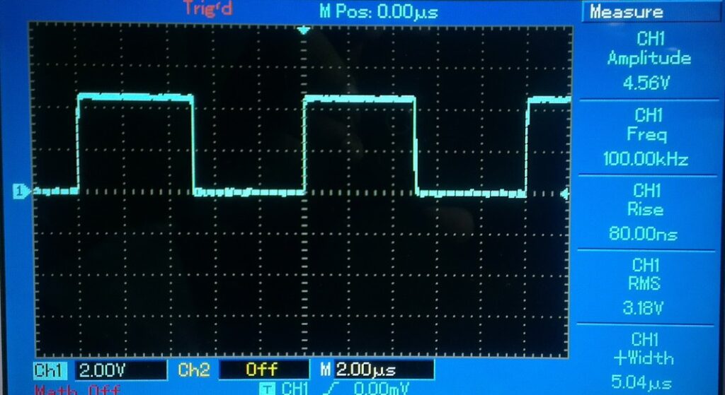
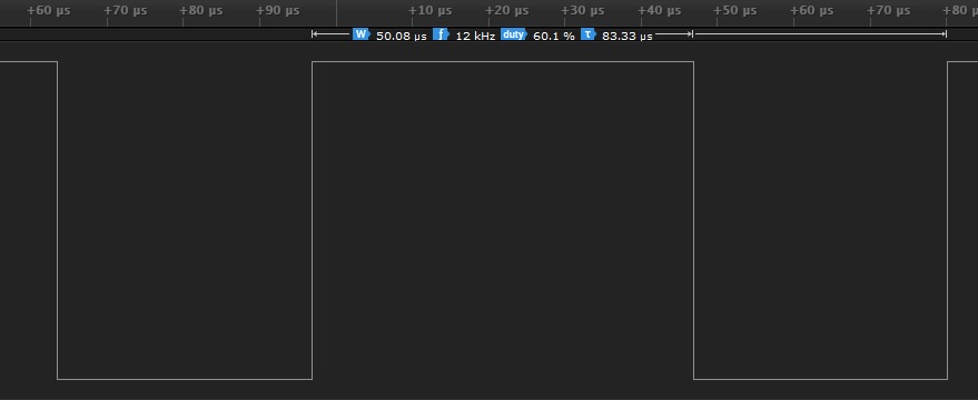
The PWM peripheral is setup with P1.0 pin as PWM channel 0. The initial frequency of the PWM is 12kHz and the duty cycle is about 60%.
 PWM0_setup(PWM_pin_is_PWM_output, \
            PWM_init_lvl_low, \
            PWM_0_pin_P10, \
            PWM_level_normal);

 PWM_clk_set(PWM_clk_sys_PS, PWM_clk_ps_sys_clk_div_2);
 PWM_set_counter(500);

 PWM_set_PWM0_T1(0);
 PWM_set_PWM0_T2(300);

 PWM_start_counter;
The following equations show us how we fabricated this frequency and duty cycle:
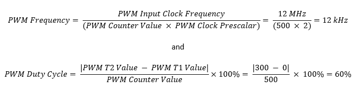
In the main, the PWM frequency if changed four times and these frequencies are 24kHz, 12kHz, 8kHz and 6kHz. The change is done about every two seconds.
Now let us see how we have to setup the PCA’s capture part. P1.7 pin (PCA0) is setup as the capture pin that would look for falling edges. PCA hardware clock is running at full system clock speed of 12MHz. The Nyquist criterion is fulfilled because PWM out frequency is not more than 24kHz.
 PCA_pin_option(0x00);

 PCA_setup(PCA_continue_counting_in_idle_mode, PCA_clk_sys_clk_div_1);
 PCA_load_counter(0x0000);

 PCA_0_mode(PCA_16_bit_falling_edge_capture);

 _enable_PCA_0_interrupt;
 _enable_PCA_counter_interrupt;
 _enable_global_interrupt;

 PCA_start_counter;
PCA interrupt will be triggered when a falling edge is detected or when there is PCA counter overflows. Both of these events will be needed. Though under a same interrupt subroutine, these events are differentiated by two separate flags. The first will be needed to make sure that we took account of any PCA overflow in between two successive captures and the second will be needed to snap PCA counter count at the moment of falling-edge detection.
 void PCA_ISR(void)
 interrupt 7
 {
     if(check_PCA_Counter_overflow_flag)
     {
       ov_cnt++;;
       clear_PCA_Counter_overflow_flag;
     }

     if(check_PCA_0_flag)
     {
       second_edge = PCA_get_CCAP0();
       clks = ((65536 * ov_cnt) + second_edge - first_edge);
       ov_cnt = 0;
       first_edge = second_edge;
       second_edge = 0;
       clear_PCA_0_flag;
     }
 }
When PCA interrupt occurs, two flags are checked. Firstly, the PCA counter overflow is checked and secondly, PCA0 interrupt flag is checked. If PCA counter overflow occurs then it is saved in a variable. This will mark that an overflow event occurred during a snap.
Since frequency measurement is done by measuring the PCA counter’s count difference between two consecutive falling edges, we need to assume that the first capture is basically the second capture instead of the first falling edge capture. When the second capture is recorded, it is measured against the first one. In this measurement, we also have to take note if any PCA overflow occurred during the captures. Note that no timer has been used so far and that is because the PCA module is doubling as a timer here.
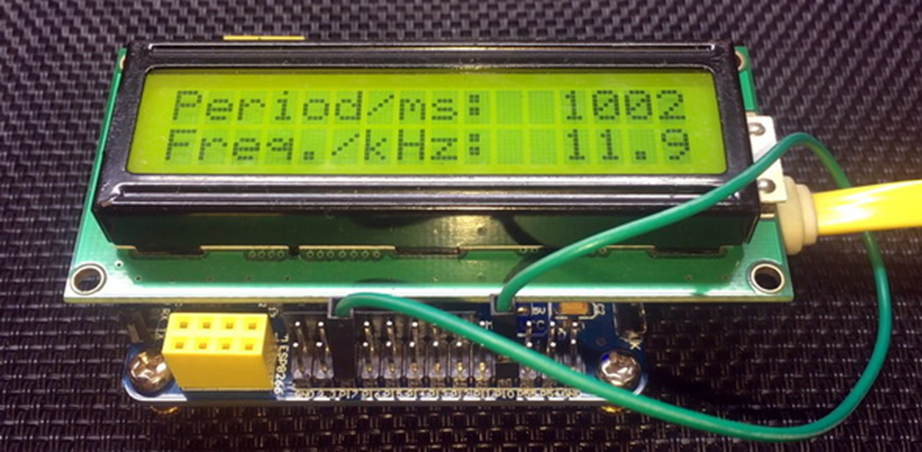
In the main, the PWM frequencies are changed periodically and the PWM frequencies are measured. The measured frequency is displayed on an LCD.
 PWM_stop_counter;

 switch(s)
 {
   case 1:
   {
     PWM_clk_set(PWM_clk_sys_PS, PWM_clk_ps_sys_clk_div_1);
     break;
   }

   case 2:
   {
     PWM_clk_set(PWM_clk_sys_PS, PWM_clk_ps_sys_clk_div_4);
     break;
   }

   case 3:
   {
     PWM_clk_set(PWM_clk_sys_PS, PWM_clk_ps_sys_clk_div_3);
     break;
   }

 default:
   {
     PWM_clk_set(PWM_clk_sys_PS, PWM_clk_ps_sys_clk_div_2);
     break;
   }
 }

 PWM_start_counter;
 delay_ms(1000);

 f = (12000.0 / ((float)clks));
 print_I(11, 0, clks);
 print_F(11, 1, f, 1);

 delay_ms(1000);

 s++;
 if(s > 3)
 {
   s = 0;
 }
Variable clks represents the count difference between capture snaps and so dividing PCA clock frequency with this count gives capture waveform frequency in hertz. I have coded 12000 instead of 12000000 as clock frequency because I want measurements to be in kHz instead of Hz.
Demo
|
|
hello.
this is a very good effort to document all and still share with us. thank you very much.
I have one doubt . which programming tool are you using ?
Hi, I am trying to understand the STC15w408as chip, and found this site after weeks of searching for something that sets the output of the GPIO pins to a different state. I have a the 28 pin stc15w and have connected it up with a FTDI board and can write to it using PlatformIO. The thing is, the GPIO ports if just switched on or do a reset they are in the HIGH state and I am trying to make them LOW when you do a reset.
Is your BSP code doing this and for what port or GPIO pin is it setting? I could change your P52 and P55 in your SETUP to the GPIO pins on my development board but not under standing the BSP Code.
Wonder if you get this post? but any help would be gratefully received.
Hi,
How Purchase the development board. Please,give the purchase link for this Development board.
https://www.alibaba.com/product-detail/Development-board-1T-STC8A8K64S4A12-single-chip_62391507065.html
https://world.taobao.com/item/600882463994.htm
https://www.amazon.ca/STC8A8K64S4A12-Development-Controller-Module-Minimal/dp/B08D3Y3R6T
How To read and write string data using IAP into memory
void IAP_erase(unsigned int address)
{
IAP_CONTR = 0x80; //?? IAP
IAP_TPS = 12;
// IAP_CONTR = IAP_WT;
IAP_CMD = IAP_erase_command;
IAP_address(address);
IAP_trigger;
_nop_();
_nop_();
_nop_();
IAP_clear;
}
void IAP_send_string(unsigned int uc_send_addr,unsigned char *uca_send_string,unsigned int uc_number_of_bytes)
{
unsigned int buff_cntr=0;
do
{
IAP_CONTR = 0x80; //?? ISP/IAP ??
IAP_TPS = (unsigned char)(11509200 / 1000000L); //??????
IAP_CMD = IAP_write_command;
// IAP_CMD = IAP_write_command;
IAP_ADDRH = uc_send_addr / 256; //??????(??????????????)
IAP_ADDRL = uc_send_addr % 256; //??????
IAP_DATA = uca_send_string[buff_cntr]; //???? ISP_DATA,????????????
IAP_trigger;//IAP_TRIG();
_nop_();
_nop_();
_nop_();
uc_send_addr++;
// uca_send_string++;
buff_cntr++;
IAP_clear;
delay_ms(8);
}while(–uc_number_of_bytes);
}
void IAP_read_string(unsigned int uc_read_addr,unsigned char *data_read,unsigned int uc_number_of_bytes)
{
unsigned int buff_cntr=0;
do{
IAP_CONTR = 0x80; //?? ISP/IAP ??
IAP_TPS = (unsigned char)(11059200 / 1000000L); //??????
IAP_CMD = IAP_read_command;
// IAP_CMD = IAP_read_command;
IAP_ADDRH = uc_read_addr / 256; //??????(??????????????)
IAP_ADDRL = uc_read_addr % 256; //??????
IAP_trigger;//IAP_TRIG(); //?? 5AH,?? A5H ? ISP/IAP ?????,
//???????
//?? A5H ?, ISP/IAP ?????????
//CPU ?? IAP ???,?????????
_nop_();
_nop_();
_nop_();
data_read[buff_cntr] = IAP_DATA; //???????
uc_read_addr++;
// data_read++;
buff_cntr++;
IAP_clear;
delay_ms(8);
}while(–uc_number_of_bytes);
}
stores only last byte to all bytes of flash memory sector… memory sector selected is 0xF600
Hi, I am using STC MCU since 10 years. Tech support is ZERO. but they are low cost, very stable. Now I have a problem when the chip that I used is obsolete. Now start to use STC8C2K64S4-28I-LQFP32 but no stc8Cxx.h file, I am using stc8Hxx.h file which compiles but in some stage freeze, the existing firmware. With stc8hxx.h file I can compile STC8F2K64S4-28I-LQFP32 and works not bad
.
I wrote them many times for the stc8Cxx.h file never got answer. Where Can I find that file?
Thank you
Give me detail 8f2k64s281MCU read and write programmer
Give me detail 8f2k64s281reed and write programmer distal
Hi. Can you explain how to use I2C in the slave mode ?
I tried STC8G1K08A i2c in slave mode. Doesn’t work (no response). It does not enter interrupt, even on a start condition (everything according to the code in the documentation). I also tried master mode – it works.
Thanks for these tutorials. I’m getting back into STCmicro coding now, having left them alone for the past several years. Back then I only used the STC89C52RC (and C54RD) but this time I’m also using the more powerful STC15 and STC8 types. Your blogs provide a wealth of useful information.
Hello,
You have done great job with all these tutorials. I am an electronics engineer trying to learn some new stuff. I am located in Greece , Europe and I would like to purchase the development board that you are using and download some datasheets in English if possible but I cannot find them anywhere. Could you please help me?
I suggest you buy from AliExpress or similar platform that is available in your country…. You can find the English datasheet here. English documentation can be found in STC’s official websites such as this one….
Thank you very much for your help!!!
i always get excited when you release new tutorials ,you are really doing a great job i wish i could write code and develop libraries like you.
Well, this is very nice and thorough tutorial indeed, many thanks!
Unfortunately I doubt there is good any reason to learn the STC platform beyond curiosity.
The STC 8051, although pretty evolved from the original 8051 ISA, does not offer anything crucial to justify the relatively high price of these micros and development tools along with certain cumbersomeness of this ancient platform.
They simply can not compete even with the legacy Cortex M0 in any way. I am even not aware about any affordable debugger/emulator for them.
All in all, I would never recommend anybody to start learning/using any 8051 without some very good reason to do so.