Exploring STC 8051 Microcontrollers – Coding

|
|
Analogue-to-Digital Converter (ADC)
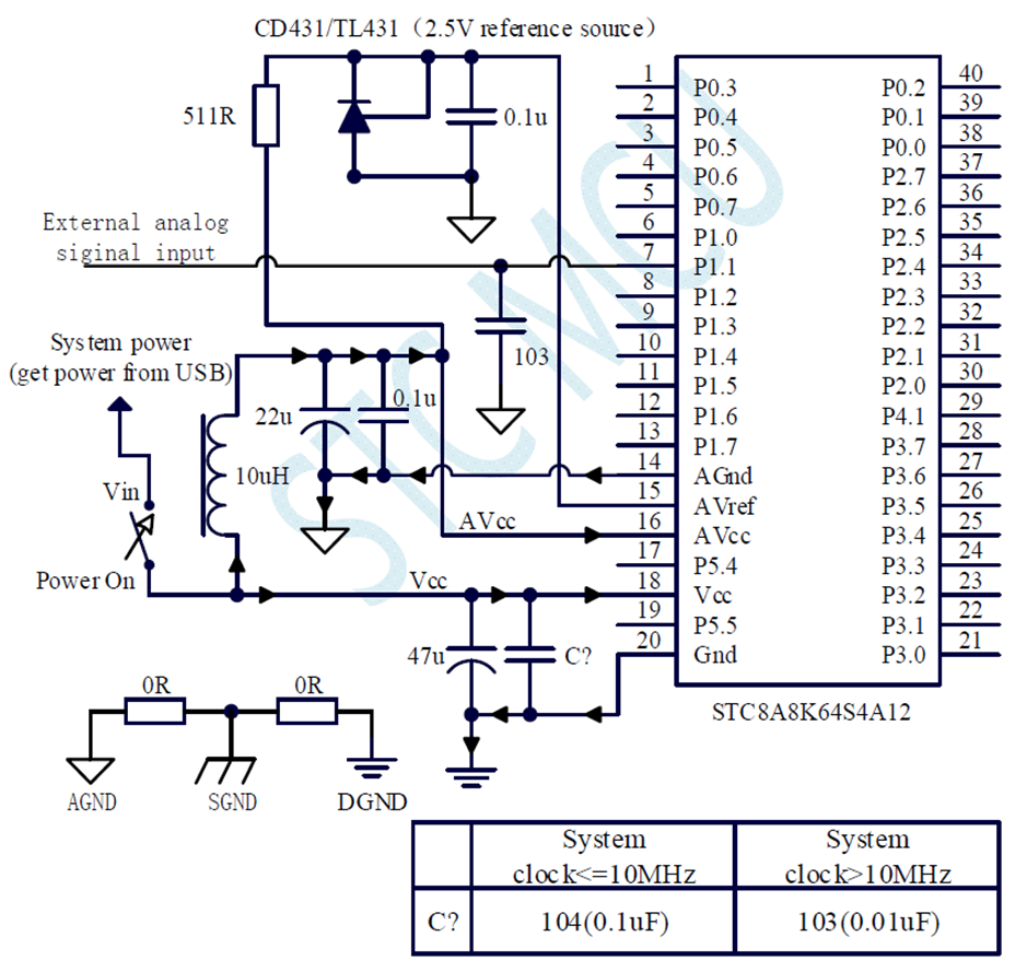
STC8A8K64S4A12’s 12-bit analogue-to-digital converter is an attractive feature. In the market, there are many enhanced 8051-core microcontrollers but most don’t have any built-in ADC while some have low resolution ones. Like the analogue comparator, the ADC of STC8A8K64S4A12 is very simple and have limited basic options. The speed of this ADC can reach up to 800ksps. However, some care needs to be taken in order to maintain accuracy and consistency in measurements. For better results it is better to use well-calibrated external voltage reference source and additional filtering. These are well documented in STC8A8K64S4A12 reference manual and a sample diagram is shown below.
Code
#include "STC8xxx.h"
#include "BSP.h"
#include "LCD.c"
#include "lcd_print.c"
void setup(void);
void main(void)
{
unsigned int ADC_count = 0x0000;
float voltage = 0.0;
setup();
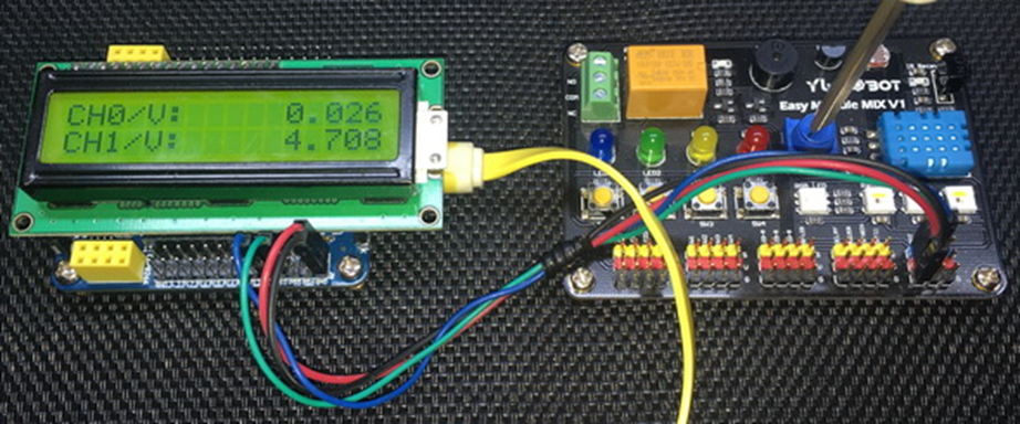
LCD_goto(0, 0);
LCD_putstr("CH0/V:");
LCD_goto(0, 1);
LCD_putstr("CH1/V:");
while(1)
{
ADC_count = ADC_get_result(CH0);
voltage = (((float)ADC_count * 5.0) / 4095.0);
print_F(10, 0, voltage, 3);
ADC_count = ADC_get_result(CH1);
voltage = (((float)ADC_count * 5.0) / 4095.0);
print_F(10, 1, voltage, 3);
delay_ms(400);
};
}
void setup(void)
{
CLK_set_sys_clk(IRC_24M, 4, MCLK_SYSCLK_no_output, MCLK_out_P54);
P10_input_mode;
P11_input_mode;
ADC_enable;
ADC_result_format_right_aligned;
ADC_set_conversion_speed(ADC_conv_256_CLKs);
LCD_init();
LCD_clear_home();
}
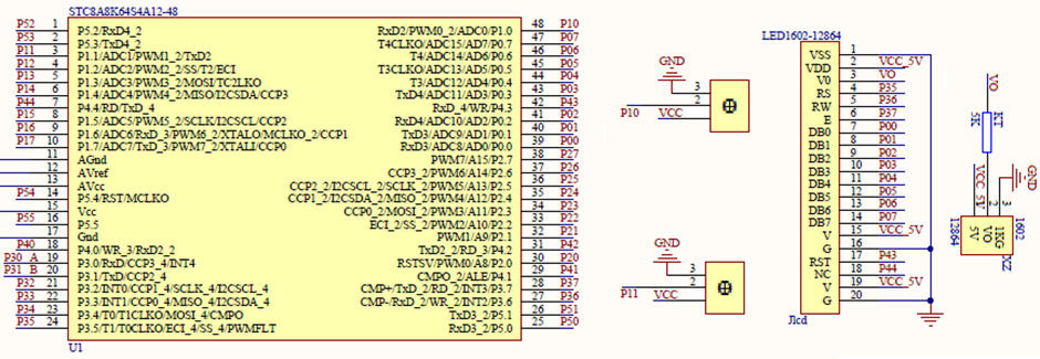
Schematic
Explanation
This ADC example utilizes polling method to get voltage reading from two ADC channels associated with pins P1.0 and P1.1.
System clock setting is very important and this is so because AD conversion speed is dependent of this clock.

where
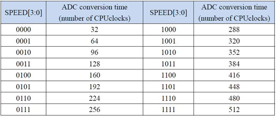
CLK_set_sys_clk(IRC_24M, 4, MCLK_SYSCLK_no_output, MCLK_out_P54);
In our case, the system clock is 6MHz and so FADC is 732Hz. Though the conversion speed is not pretty impressive, it is good enough for this example as sensing voltage variations are not rapid. Nyquist criterion should always be kept in mind while sampling analogue signals.
ADC Input pins need to declared as inputs.
 P10_input_mode;
 P11_input_mode;
ADC setup is pretty straight. All we need to do is to enable the ADC, select data output alignment and ADC clock speed prescalar.
ADC_enable;
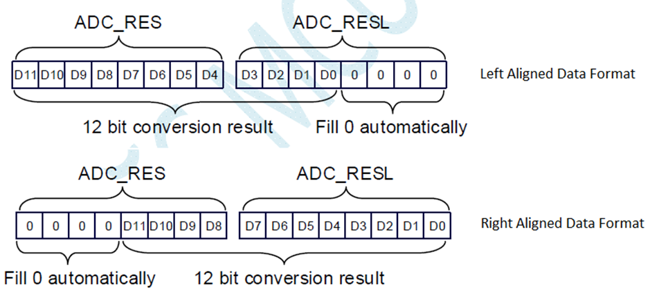
ADC_result_format_right_aligned;
ADC_set_conversion_speed(ADC_conv_256_CLKs);
Data output can be either left-aligned or right-aligned. Right-aligned data is easy to read and that is why it my choice.
The ADC reading function reveals this fact.
 unsigned int ADC_get_result(unsigned char channel)
 {
     register unsigned int value = 0x0000;

     ADC_set_channel(channel);
     delay_ms(1);

     ADC_start_conversion;
     while(!check_ADC_flag);
     clear_ADC_flag;

     value = ((ADC_RES << 8) | ADC_RESL);

     return value;
 }
In the main, ADC channels 0 and 1 are read and their readings are converted to voltage. The voltages are shown on an LCD.
 ADC_count = ADC_get_result(CH0);
 voltage = (((float)ADC_count * 5.0) / 4095.0);
 print_F(10, 0, voltage, 3);

 ADC_count = ADC_get_result(CH1);
 voltage = (((float)ADC_count * 5.0) / 4095.0);
 print_F(10, 1, voltage, 3);

 delay_ms(400);
ADC reading can be improved by applying several techniques like using filters, averaging technique and so on. Special attention is needed while designing PCBs in order to minimize cross-talk between channels and noise from onboard digital circuitry.
Generally, AD conversion should be fast, ADC I/O pins must be set in high impedance mode and AVCC to VCC voltage difference should not be more than 0.3V.
Demo
|
|
hello.
this is a very good effort to document all and still share with us. thank you very much.
I have one doubt . which programming tool are you using ?
Hi, I am trying to understand the STC15w408as chip, and found this site after weeks of searching for something that sets the output of the GPIO pins to a different state. I have a the 28 pin stc15w and have connected it up with a FTDI board and can write to it using PlatformIO. The thing is, the GPIO ports if just switched on or do a reset they are in the HIGH state and I am trying to make them LOW when you do a reset.
Is your BSP code doing this and for what port or GPIO pin is it setting? I could change your P52 and P55 in your SETUP to the GPIO pins on my development board but not under standing the BSP Code.
Wonder if you get this post? but any help would be gratefully received.
Hi,
How Purchase the development board. Please,give the purchase link for this Development board.
https://www.alibaba.com/product-detail/Development-board-1T-STC8A8K64S4A12-single-chip_62391507065.html
https://world.taobao.com/item/600882463994.htm
https://www.amazon.ca/STC8A8K64S4A12-Development-Controller-Module-Minimal/dp/B08D3Y3R6T
How To read and write string data using IAP into memory
void IAP_erase(unsigned int address)
{
IAP_CONTR = 0x80; //?? IAP
IAP_TPS = 12;
// IAP_CONTR = IAP_WT;
IAP_CMD = IAP_erase_command;
IAP_address(address);
IAP_trigger;
_nop_();
_nop_();
_nop_();
IAP_clear;
}
void IAP_send_string(unsigned int uc_send_addr,unsigned char *uca_send_string,unsigned int uc_number_of_bytes)
{
unsigned int buff_cntr=0;
do
{
IAP_CONTR = 0x80; //?? ISP/IAP ??
IAP_TPS = (unsigned char)(11509200 / 1000000L); //??????
IAP_CMD = IAP_write_command;
// IAP_CMD = IAP_write_command;
IAP_ADDRH = uc_send_addr / 256; //??????(??????????????)
IAP_ADDRL = uc_send_addr % 256; //??????
IAP_DATA = uca_send_string[buff_cntr]; //???? ISP_DATA,????????????
IAP_trigger;//IAP_TRIG();
_nop_();
_nop_();
_nop_();
uc_send_addr++;
// uca_send_string++;
buff_cntr++;
IAP_clear;
delay_ms(8);
}while(–uc_number_of_bytes);
}
void IAP_read_string(unsigned int uc_read_addr,unsigned char *data_read,unsigned int uc_number_of_bytes)
{
unsigned int buff_cntr=0;
do{
IAP_CONTR = 0x80; //?? ISP/IAP ??
IAP_TPS = (unsigned char)(11059200 / 1000000L); //??????
IAP_CMD = IAP_read_command;
// IAP_CMD = IAP_read_command;
IAP_ADDRH = uc_read_addr / 256; //??????(??????????????)
IAP_ADDRL = uc_read_addr % 256; //??????
IAP_trigger;//IAP_TRIG(); //?? 5AH,?? A5H ? ISP/IAP ?????,
//???????
//?? A5H ?, ISP/IAP ?????????
//CPU ?? IAP ???,?????????
_nop_();
_nop_();
_nop_();
data_read[buff_cntr] = IAP_DATA; //???????
uc_read_addr++;
// data_read++;
buff_cntr++;
IAP_clear;
delay_ms(8);
}while(–uc_number_of_bytes);
}
stores only last byte to all bytes of flash memory sector… memory sector selected is 0xF600
Hi, I am using STC MCU since 10 years. Tech support is ZERO. but they are low cost, very stable. Now I have a problem when the chip that I used is obsolete. Now start to use STC8C2K64S4-28I-LQFP32 but no stc8Cxx.h file, I am using stc8Hxx.h file which compiles but in some stage freeze, the existing firmware. With stc8hxx.h file I can compile STC8F2K64S4-28I-LQFP32 and works not bad
.
I wrote them many times for the stc8Cxx.h file never got answer. Where Can I find that file?
Thank you
Give me detail 8f2k64s281MCU read and write programmer
Give me detail 8f2k64s281reed and write programmer distal
Hi. Can you explain how to use I2C in the slave mode ?
I tried STC8G1K08A i2c in slave mode. Doesn’t work (no response). It does not enter interrupt, even on a start condition (everything according to the code in the documentation). I also tried master mode – it works.
Thanks for these tutorials. I’m getting back into STCmicro coding now, having left them alone for the past several years. Back then I only used the STC89C52RC (and C54RD) but this time I’m also using the more powerful STC15 and STC8 types. Your blogs provide a wealth of useful information.
Hello,
You have done great job with all these tutorials. I am an electronics engineer trying to learn some new stuff. I am located in Greece , Europe and I would like to purchase the development board that you are using and download some datasheets in English if possible but I cannot find them anywhere. Could you please help me?
I suggest you buy from AliExpress or similar platform that is available in your country…. You can find the English datasheet here. English documentation can be found in STC’s official websites such as this one….
Thank you very much for your help!!!
i always get excited when you release new tutorials ,you are really doing a great job i wish i could write code and develop libraries like you.
Well, this is very nice and thorough tutorial indeed, many thanks!
Unfortunately I doubt there is good any reason to learn the STC platform beyond curiosity.
The STC 8051, although pretty evolved from the original 8051 ISA, does not offer anything crucial to justify the relatively high price of these micros and development tools along with certain cumbersomeness of this ancient platform.
They simply can not compete even with the legacy Cortex M0 in any way. I am even not aware about any affordable debugger/emulator for them.
All in all, I would never recommend anybody to start learning/using any 8051 without some very good reason to do so.