Exploring STC 8051 Microcontrollers – Coding

|
|
Using PCA to Measure Pulse Width from HCSR-04 SONAR Module
Apart from frequency measurement, we can apply the same input capture technique to measure pulse widths or PWM duty cycles. Pulse width measurement requires capturing PCA counts of two successive opposite edges unlike two successive same edges. In this segment, we will see how we can measure distance measured by a HCSR-04 SONAR sensor by measuring pulse width output from it.
Code
 #include "STC8xxx.h"
 #include "BSP.h"
 #include "LCD.c"
 #include "lcd_print.c"

 unsigned char state = 0x00;
 unsigned int pulse_width = 0x0000;

 void setup(void);

 void PCA_ISR(void)
 interrupt 7
 {
   if(check_PCA_0_flag)
   {
     state ^= 1;
     clear_PCA_0_flag;
   }

   switch(state)
   {
     case 1:
     {
       PCA_load_counter(0x0000);
       break;
     }

     default:
     {
       pulse_width = PCA_get_CCAP0();
       break;
     }
   }
 }

 void main(void)
 {
   float range = 0.0;

   setup();

   LCD_goto(0, 0);
   LCD_putstr("Range/cm:");
   LCD_goto(0, 1);
   LCD_putstr("Pulse/us:");

   while(1)
   {
     P55_low;
     delay_ms(10);

     P16_high;
     delay_us(10);
     P16_low;
     P55_high;

     range = ((((float)pulse_width) / 58.0));
     print_F(10, 0, range, 1);
     print_I(10, 1, pulse_width);

     delay_ms(490);
   };
 }

 void setup(void)
 {
   CLK_set_sys_clk(IRC_24M, 2, MCLK_SYSCLK_no_output, MCLK_out_P54);

   P16_push_pull_mode;
   P55_open_drain_mode;

   PCA_pin_option(0x00);

   PCA_setup(PCA_continue_counting_in_idle_mode, PCA_clk_sys_clk_div_12);
   PCA_load_counter(0x0000);

   PCA_0_mode(PCA_16_bit_both_edge_capture);

   _enable_PCA_0_interrupt;
   _enable_global_interrupt;

   PCA_start_counter;

   LCD_init();
   LCD_clear_home();
 }
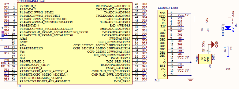
Schematic
Explanation
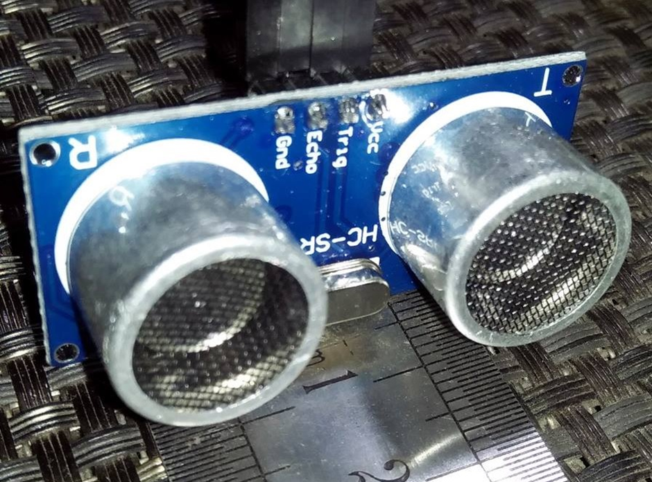
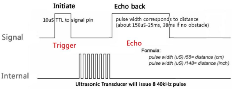
HC-SR04 SONAR sensor works by sending a stream of ultrasonic pulses and then timing how long it took for an echo to bounce back from a nearby object. Based on timing, the sensor gives a pulse of variable width. The pulse width is a representation of distance or object range.
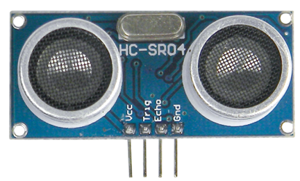
There are two pins apart from the power supply pins and these are needed to communicate with the sensor. When the trigger pin of the sensor is pulled high for about 10μs, the sensor acknowledges this short duration pulse as a command from its host micro to measure and return range data. A pulse output from the echo pin is the representation of distance.
Now let’s see how the code is working in this example. Firstly, the system clock is set to 12MHz.
CLK_set_sys_clk(IRC_24M, 2, MCLK_SYSCLK_no_output, MCLK_out_P54);
Pins P1.6 and P1.7 are tied to trigger and echo pins of HC-SR04 sensor respectively.
The PCA hardware is setup by setting its clock to 1MHz. Thus, each of PCA counter’s count is equal to 1μs tick. Default PCA pin configuration is used. The PCA counter is set to 0 count and 16-bit both edge capture mode is selected. Interrupt method is used and so PCA and global interrupts are enabled before starting the PCA counter.
 PCA_pin_option(0x00);

 PCA_setup(PCA_continue_counting_in_idle_mode, PCA_clk_sys_clk_div_12);
 PCA_load_counter(0x0000);

 PCA_0_mode(PCA_16_bit_both_edge_capture);

 _enable_PCA_0_interrupt;
 _enable_global_interrupt;

 PCA_start_counter;
The PCA hardware is now ready to detect edge transitions. When transitions occur, PCA interrupt is triggered. During a low-to-high transition or rising edge, the PCA counter is reset to 0 count and left to continue counting. Upon detecting a high-to-low transition or falling edge, the PCA counter is read.
 void PCA_ISR(void)
 interrupt 7
 {
   if(check_PCA_0_flag)
   {
     state ^= 1;
     clear_PCA_0_flag;
   }

   switch(state)
   {
     case 1:
     {
       PCA_load_counter(0x0000);
       break;
     }

     default:
     {
       pulse_width = PCA_get_CCAP0();
       break;
     }
   }
 }
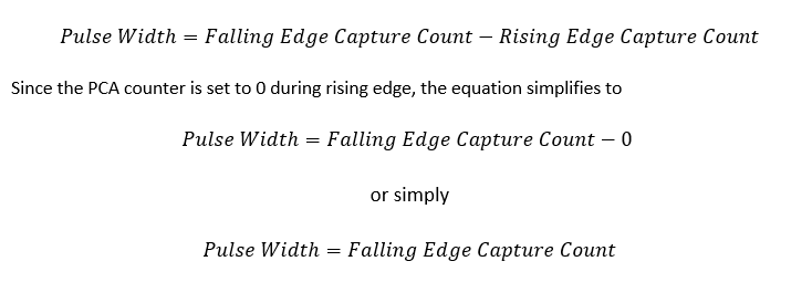
Since the PCA counter is counting with 1µs resolution, the falling edge capture count is the pulse width period in microseconds.

In the main loop, the SONAR sensor is triggered and the result from the PCA interrupt is processed. Target object distance detected by the sensor is a function of pulse width measured in microseconds. Thus, as per datasheet of the sensor, pulse width divided by 58 is equal to distance in centimeters.

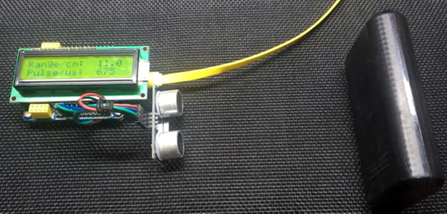
The range and the captured pulse width are displayed in an LCD after performing the aforementioned computations.
 P55_low;
 delay_ms(10);

 P16_high;
 delay_us(10);
 P16_low;
 P55_high;

 range = ((((float)pulse_width) / 58.0));
 print_F(10, 0, range, 1);
 print_I(10, 1, pulse_width);

 delay_ms(490);
Demo
|
|
hello.
this is a very good effort to document all and still share with us. thank you very much.
I have one doubt . which programming tool are you using ?
Hi, I am trying to understand the STC15w408as chip, and found this site after weeks of searching for something that sets the output of the GPIO pins to a different state. I have a the 28 pin stc15w and have connected it up with a FTDI board and can write to it using PlatformIO. The thing is, the GPIO ports if just switched on or do a reset they are in the HIGH state and I am trying to make them LOW when you do a reset.
Is your BSP code doing this and for what port or GPIO pin is it setting? I could change your P52 and P55 in your SETUP to the GPIO pins on my development board but not under standing the BSP Code.
Wonder if you get this post? but any help would be gratefully received.
Hi,
How Purchase the development board. Please,give the purchase link for this Development board.
https://www.alibaba.com/product-detail/Development-board-1T-STC8A8K64S4A12-single-chip_62391507065.html
https://world.taobao.com/item/600882463994.htm
https://www.amazon.ca/STC8A8K64S4A12-Development-Controller-Module-Minimal/dp/B08D3Y3R6T
How To read and write string data using IAP into memory
void IAP_erase(unsigned int address)
{
IAP_CONTR = 0x80; //?? IAP
IAP_TPS = 12;
// IAP_CONTR = IAP_WT;
IAP_CMD = IAP_erase_command;
IAP_address(address);
IAP_trigger;
_nop_();
_nop_();
_nop_();
IAP_clear;
}
void IAP_send_string(unsigned int uc_send_addr,unsigned char *uca_send_string,unsigned int uc_number_of_bytes)
{
unsigned int buff_cntr=0;
do
{
IAP_CONTR = 0x80; //?? ISP/IAP ??
IAP_TPS = (unsigned char)(11509200 / 1000000L); //??????
IAP_CMD = IAP_write_command;
// IAP_CMD = IAP_write_command;
IAP_ADDRH = uc_send_addr / 256; //??????(??????????????)
IAP_ADDRL = uc_send_addr % 256; //??????
IAP_DATA = uca_send_string[buff_cntr]; //???? ISP_DATA,????????????
IAP_trigger;//IAP_TRIG();
_nop_();
_nop_();
_nop_();
uc_send_addr++;
// uca_send_string++;
buff_cntr++;
IAP_clear;
delay_ms(8);
}while(–uc_number_of_bytes);
}
void IAP_read_string(unsigned int uc_read_addr,unsigned char *data_read,unsigned int uc_number_of_bytes)
{
unsigned int buff_cntr=0;
do{
IAP_CONTR = 0x80; //?? ISP/IAP ??
IAP_TPS = (unsigned char)(11059200 / 1000000L); //??????
IAP_CMD = IAP_read_command;
// IAP_CMD = IAP_read_command;
IAP_ADDRH = uc_read_addr / 256; //??????(??????????????)
IAP_ADDRL = uc_read_addr % 256; //??????
IAP_trigger;//IAP_TRIG(); //?? 5AH,?? A5H ? ISP/IAP ?????,
//???????
//?? A5H ?, ISP/IAP ?????????
//CPU ?? IAP ???,?????????
_nop_();
_nop_();
_nop_();
data_read[buff_cntr] = IAP_DATA; //???????
uc_read_addr++;
// data_read++;
buff_cntr++;
IAP_clear;
delay_ms(8);
}while(–uc_number_of_bytes);
}
stores only last byte to all bytes of flash memory sector… memory sector selected is 0xF600
Hi, I am using STC MCU since 10 years. Tech support is ZERO. but they are low cost, very stable. Now I have a problem when the chip that I used is obsolete. Now start to use STC8C2K64S4-28I-LQFP32 but no stc8Cxx.h file, I am using stc8Hxx.h file which compiles but in some stage freeze, the existing firmware. With stc8hxx.h file I can compile STC8F2K64S4-28I-LQFP32 and works not bad
.
I wrote them many times for the stc8Cxx.h file never got answer. Where Can I find that file?
Thank you
Give me detail 8f2k64s281MCU read and write programmer
Give me detail 8f2k64s281reed and write programmer distal
Hi. Can you explain how to use I2C in the slave mode ?
I tried STC8G1K08A i2c in slave mode. Doesn’t work (no response). It does not enter interrupt, even on a start condition (everything according to the code in the documentation). I also tried master mode – it works.
Thanks for these tutorials. I’m getting back into STCmicro coding now, having left them alone for the past several years. Back then I only used the STC89C52RC (and C54RD) but this time I’m also using the more powerful STC15 and STC8 types. Your blogs provide a wealth of useful information.
Hello,
You have done great job with all these tutorials. I am an electronics engineer trying to learn some new stuff. I am located in Greece , Europe and I would like to purchase the development board that you are using and download some datasheets in English if possible but I cannot find them anywhere. Could you please help me?
I suggest you buy from AliExpress or similar platform that is available in your country…. You can find the English datasheet here. English documentation can be found in STC’s official websites such as this one….
Thank you very much for your help!!!
i always get excited when you release new tutorials ,you are really doing a great job i wish i could write code and develop libraries like you.
Well, this is very nice and thorough tutorial indeed, many thanks!
Unfortunately I doubt there is good any reason to learn the STC platform beyond curiosity.
The STC 8051, although pretty evolved from the original 8051 ISA, does not offer anything crucial to justify the relatively high price of these micros and development tools along with certain cumbersomeness of this ancient platform.
They simply can not compete even with the legacy Cortex M0 in any way. I am even not aware about any affordable debugger/emulator for them.
All in all, I would never recommend anybody to start learning/using any 8051 without some very good reason to do so.