Exploring STC 8051 Microcontrollers – Coding

|
|
Using Single Channel Enhanced PWM to Drive a Servo Motor
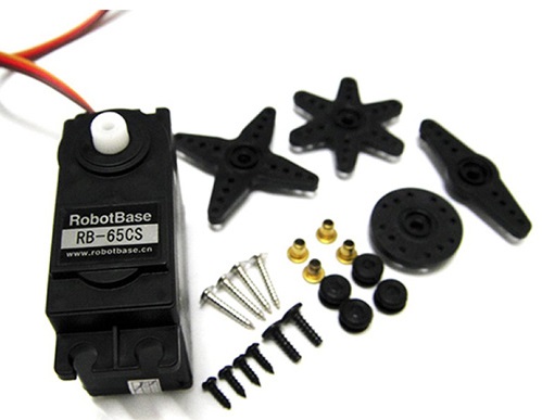
Servo motors have varieties of applications both in industrial automation and robotics arena. They are simple and can be digitally controlled with only one wire and over long distances. However, this one wire digital control mechanism is somewhat unique and sometimes stressful because trains of low duty cycle pulses are needed to be sent constantly in order to lock a particular angular position.
To resolve this issue, we can use GPIOs coupled with software delays or timers or PWMs module to control one or several servo motors. One key advantage of using PWM modules over GPIOs is the accuracy in timing since PWM modules use timer-counters for timing instead of software delays. In this section, we will see how we can use a PWM module to drive an ordinary servo motor. STC8A8K64S4A12’s enhanced PWM module is used as the PWM generator here.
Code
 #include "STC8xxx.h"
 #include "BSP.h"

 #define servo_min_duty     800
 #define servo_max_duty    2200
 #define step_change          5

 void setup(void);
 void PWM_idle(void);

 void main(void)
 {
   unsigned int i = 0x0000;

   setup();

   while(1)
   {
     for(i = servo_min_duty; i < servo_max_duty; i += step_change)
     {
       PWM_set_PWM0_T1(i);
       delay_ms(4);
     }
     for(i = servo_max_duty; i > servo_min_duty; i -= step_change)
     {
       PWM_set_PWM0_T1(i);
       delay_ms(4);
     }
   };
 }

 void setup(void)
 {
   CLK_set_sys_clk(IRC_24M, 2, MCLK_SYSCLK_no_output, MCLK_out_P54);

   PWM_clk_set(PWM_clk_sys_PS, PWM_clk_ps_sys_clk_div_12);
   PWM_set_counter(20000);

   PWM0_setup(PWM_pin_is_PWM_output, \
              PWM_init_lvl_low, \
              PWM_0_pin_P20, \
              PWM_level_normal);

   PWM_set_PWM0_T1(1000);
   PWM_set_PWM0_T2(0);

   PWM_start_counter;
 }
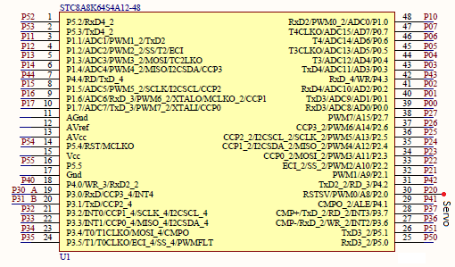
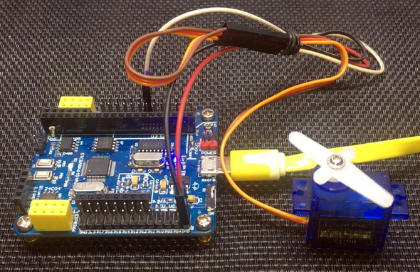
Schematic
Explanation
Servo motors typically have timing diagrams as shown below:
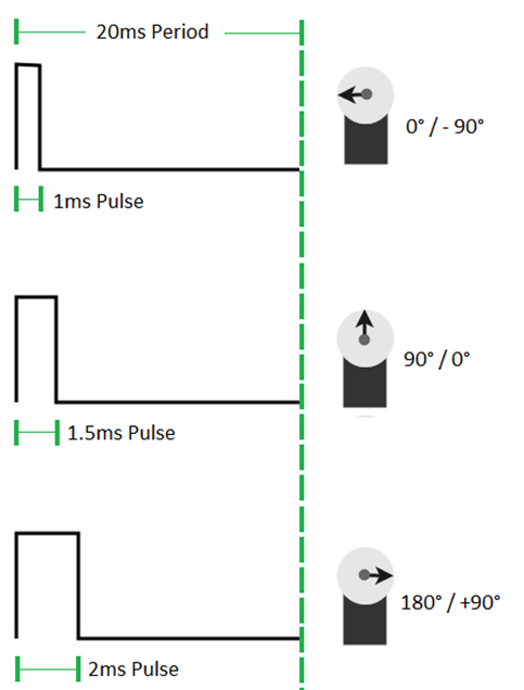
Each pulse has a period of 20ms but the duty cycle/pulse high time is varied from 5 – 10% to rotate from one direction to the other. This clearly demonstrates why timing is very important for servo motors.
The demo program here is coded to run at 12MHz.
CLK_set_sys_clk(IRC_24M, 2, MCLK_SYSCLK_no_output, MCLK_out_P54);
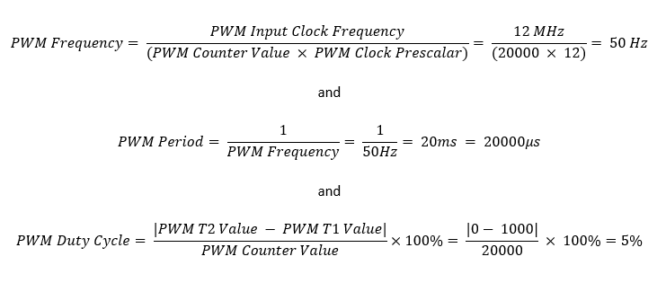
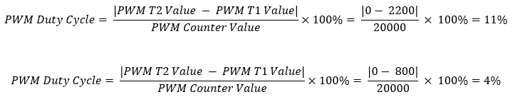
PWM0 hardware is configured to use P2.0 pin as servo control pin. The PWM hardware clock is set to 1MHz by using system clock as clock source and dividing it with a prescalar of 12. This is, however, not the PWM output frequency because the PWM counter is loaded with count value of 20000. The resultant PWM output frequency is 50Hz as shown in the following equation:
The following codes does all mentioned so far. However, PWM setup is not just about timing only. PWM hardware also need an output. We have to mention which PWM we would be using and what would be its level and polarity.
 PWM_clk_set(PWM_clk_sys_PS, PWM_clk_ps_sys_clk_div_12);

 PWM_set_counter(20000);

 PWM0_setup(PWM_pin_is_PWM_output, \
            PWM_init_lvl_low, \
            PWM_0_pin_P20, \
            PWM_level_normal);

 PWM_set_PWM0_T1(1000);
 PWM_set_PWM0_T2(0);

 PWM_start_counter;
After setting all these, we just have to start the PWM hardware by starting the PWM counter.
Inside the main loop, the duty cycle of the PWM is slightly varied in steps. This results in smooth servo motion. Note that the maximum and minimum duty cycles are not 2000 and 1000 respectively as they ideally should have been. This is so because these values are typical ones and not always practical. Thus, the maximum and minimum duty cycles are set to 2200 and 800 respectively.
The 1% variation is needed because of non-ideality.
 #define servo_min_duty     800
 #define servo_max_duty    2200
 #define step_change          5

 ....

 for(i = servo_min_duty; i < servo_max_duty; i += step_change)
 {
   PWM_set_PWM0_T1(i);
   delay_ms(4);
 }

 for(i = servo_max_duty; i > servo_min_duty; i -= step_change)
 {
   PWM_set_PWM0_T1(i);
   delay_ms(4);
 }
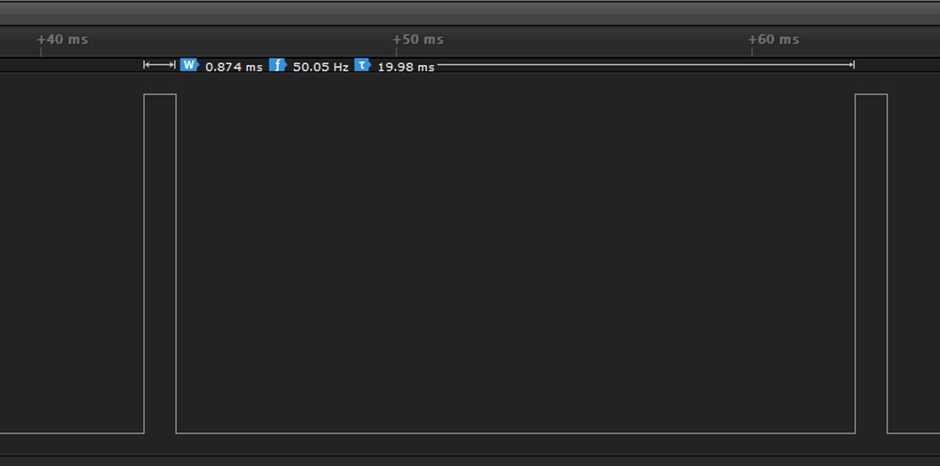
The logic analyser data shown below verifies that whatever stated so far has been achieved.
Demo
|
|
hello.
this is a very good effort to document all and still share with us. thank you very much.
I have one doubt . which programming tool are you using ?
Hi, I am trying to understand the STC15w408as chip, and found this site after weeks of searching for something that sets the output of the GPIO pins to a different state. I have a the 28 pin stc15w and have connected it up with a FTDI board and can write to it using PlatformIO. The thing is, the GPIO ports if just switched on or do a reset they are in the HIGH state and I am trying to make them LOW when you do a reset.
Is your BSP code doing this and for what port or GPIO pin is it setting? I could change your P52 and P55 in your SETUP to the GPIO pins on my development board but not under standing the BSP Code.
Wonder if you get this post? but any help would be gratefully received.
Hi,
How Purchase the development board. Please,give the purchase link for this Development board.
https://www.alibaba.com/product-detail/Development-board-1T-STC8A8K64S4A12-single-chip_62391507065.html
https://world.taobao.com/item/600882463994.htm
https://www.amazon.ca/STC8A8K64S4A12-Development-Controller-Module-Minimal/dp/B08D3Y3R6T
How To read and write string data using IAP into memory
void IAP_erase(unsigned int address)
{
IAP_CONTR = 0x80; //?? IAP
IAP_TPS = 12;
// IAP_CONTR = IAP_WT;
IAP_CMD = IAP_erase_command;
IAP_address(address);
IAP_trigger;
_nop_();
_nop_();
_nop_();
IAP_clear;
}
void IAP_send_string(unsigned int uc_send_addr,unsigned char *uca_send_string,unsigned int uc_number_of_bytes)
{
unsigned int buff_cntr=0;
do
{
IAP_CONTR = 0x80; //?? ISP/IAP ??
IAP_TPS = (unsigned char)(11509200 / 1000000L); //??????
IAP_CMD = IAP_write_command;
// IAP_CMD = IAP_write_command;
IAP_ADDRH = uc_send_addr / 256; //??????(??????????????)
IAP_ADDRL = uc_send_addr % 256; //??????
IAP_DATA = uca_send_string[buff_cntr]; //???? ISP_DATA,????????????
IAP_trigger;//IAP_TRIG();
_nop_();
_nop_();
_nop_();
uc_send_addr++;
// uca_send_string++;
buff_cntr++;
IAP_clear;
delay_ms(8);
}while(–uc_number_of_bytes);
}
void IAP_read_string(unsigned int uc_read_addr,unsigned char *data_read,unsigned int uc_number_of_bytes)
{
unsigned int buff_cntr=0;
do{
IAP_CONTR = 0x80; //?? ISP/IAP ??
IAP_TPS = (unsigned char)(11059200 / 1000000L); //??????
IAP_CMD = IAP_read_command;
// IAP_CMD = IAP_read_command;
IAP_ADDRH = uc_read_addr / 256; //??????(??????????????)
IAP_ADDRL = uc_read_addr % 256; //??????
IAP_trigger;//IAP_TRIG(); //?? 5AH,?? A5H ? ISP/IAP ?????,
//???????
//?? A5H ?, ISP/IAP ?????????
//CPU ?? IAP ???,?????????
_nop_();
_nop_();
_nop_();
data_read[buff_cntr] = IAP_DATA; //???????
uc_read_addr++;
// data_read++;
buff_cntr++;
IAP_clear;
delay_ms(8);
}while(–uc_number_of_bytes);
}
stores only last byte to all bytes of flash memory sector… memory sector selected is 0xF600
Hi, I am using STC MCU since 10 years. Tech support is ZERO. but they are low cost, very stable. Now I have a problem when the chip that I used is obsolete. Now start to use STC8C2K64S4-28I-LQFP32 but no stc8Cxx.h file, I am using stc8Hxx.h file which compiles but in some stage freeze, the existing firmware. With stc8hxx.h file I can compile STC8F2K64S4-28I-LQFP32 and works not bad
.
I wrote them many times for the stc8Cxx.h file never got answer. Where Can I find that file?
Thank you
Give me detail 8f2k64s281MCU read and write programmer
Give me detail 8f2k64s281reed and write programmer distal
Hi. Can you explain how to use I2C in the slave mode ?
I tried STC8G1K08A i2c in slave mode. Doesn’t work (no response). It does not enter interrupt, even on a start condition (everything according to the code in the documentation). I also tried master mode – it works.
Thanks for these tutorials. I’m getting back into STCmicro coding now, having left them alone for the past several years. Back then I only used the STC89C52RC (and C54RD) but this time I’m also using the more powerful STC15 and STC8 types. Your blogs provide a wealth of useful information.
Hello,
You have done great job with all these tutorials. I am an electronics engineer trying to learn some new stuff. I am located in Greece , Europe and I would like to purchase the development board that you are using and download some datasheets in English if possible but I cannot find them anywhere. Could you please help me?
I suggest you buy from AliExpress or similar platform that is available in your country…. You can find the English datasheet here. English documentation can be found in STC’s official websites such as this one….
Thank you very much for your help!!!
i always get excited when you release new tutorials ,you are really doing a great job i wish i could write code and develop libraries like you.
Well, this is very nice and thorough tutorial indeed, many thanks!
Unfortunately I doubt there is good any reason to learn the STC platform beyond curiosity.
The STC 8051, although pretty evolved from the original 8051 ISA, does not offer anything crucial to justify the relatively high price of these micros and development tools along with certain cumbersomeness of this ancient platform.
They simply can not compete even with the legacy Cortex M0 in any way. I am even not aware about any affordable debugger/emulator for them.
All in all, I would never recommend anybody to start learning/using any 8051 without some very good reason to do so.