Exploring STC 8051 Microcontrollers – Coding

|
|
Using PCA to Generate PWM
Unlike enhanced PWM module, PCA module can used to generate PWMs of different resolutions. However, PCA-generated PWMs are like general purpose PWMs and do not have additional functionalities. These PWMs can be used for simple tasks like driving LEDs, servo motors, simple motor controls, simple DC-DC converters, etc.
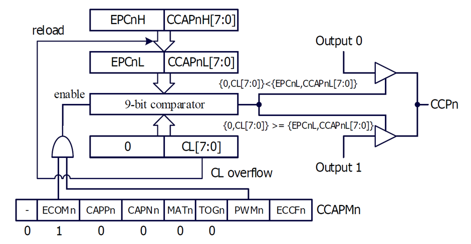
The following block diagram shows PCA module in 8-bit PWM mode. The 9-bit internal comparator compares the values CL and CCAPnL + EPCnL. When CL is equal or greater than CCAPnL + EPCnL, the PWM output is set high and when CL is less than CCAPnL + EPCnL, the PWM output is set low. Thus, CCAPnL + EPCnL are responsible for the duty cycle of PWM because CL keeps counting with each tick of PCA clock. When CL overflows, CCAPnL + EPCnL are reloaded automatically with the contents of CCAPnH + EPCnH. Updating CCAPnH + EPCnH, results in the alternation of PWM duty cycle. The same concept is true for PCA PWMs of other resolutions. Similar strategies are applied for PCA PWMs of other resolutions.
Code
 #include "STC8xxx.h"
 #include "BSP.h"

 void setup(void);
 void PWM_idle(void);

 void main(void)
 {
   signed int j = 0x0000;

   setup();

   while(1)
   {
     for(j = 0; j < 256; j++)
     {
       PCA_0_8_bit_PWM_reload_value(255 - j);
       PCA_1_8_bit_PWM_reload_value(j);
       PCA_2_8_bit_PWM_reload_value(255 - j);
       PCA_3_8_bit_PWM_reload_value(j);
       delay_ms(10);
     }

     for(j = 255; j > -1; j--)
     {
       PCA_0_8_bit_PWM_reload_value(255 - j);
       PCA_1_8_bit_PWM_reload_value(j);
       PCA_2_8_bit_PWM_reload_value(255 - j);
       PCA_3_8_bit_PWM_reload_value(j);
       delay_ms(10);
     }
   };
 }

 void setup(void)
 {
   CLK_set_sys_clk(IRC_24M, 2, MCLK_SYSCLK_no_output, MCLK_out_P54);

   PCA_pin_option(0x10);

   PCA_setup(PCA_continue_counting_in_idle_mode, PCA_clk_sys_clk_div_1);

   PCA_n_PWM(0, PCA_PWM_without_interrupt, PCA_8_bit_PWM);
   PCA_n_PWM(1, PCA_PWM_without_interrupt, PCA_8_bit_PWM);
   PCA_n_PWM(2, PCA_PWM_without_interrupt, PCA_8_bit_PWM);
   PCA_n_PWM(3, PCA_PWM_without_interrupt, PCA_8_bit_PWM);

   PCA_0_8_bit_PWM_compare_value(0);
   PCA_0_8_bit_PWM_reload_value(0);

   PCA_1_8_bit_PWM_compare_value(0);
   PCA_1_8_bit_PWM_reload_value(0);

   PCA_2_8_bit_PWM_compare_value(0);
   PCA_2_8_bit_PWM_reload_value(0);

   PCA_3_8_bit_PWM_compare_value(0);
   PCA_3_8_bit_PWM_reload_value(0);

   PCA_load_counter(0);

   PCA_start_counter;
 }
Schematic
Explanation
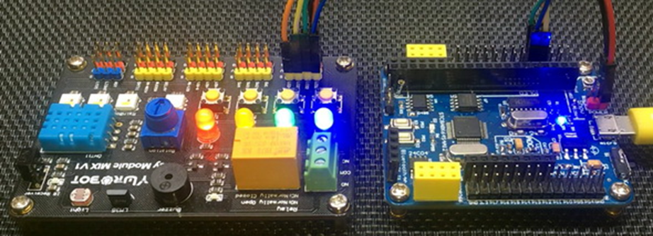
In this example, four PCA PWM channels are simply used to drive LEDs of different colors.
The system clock is set to 12MHz.
CLK_set_sys_clk(IRC_24M, 2, MCLK_SYSCLK_no_output, MCLK_out_P54);
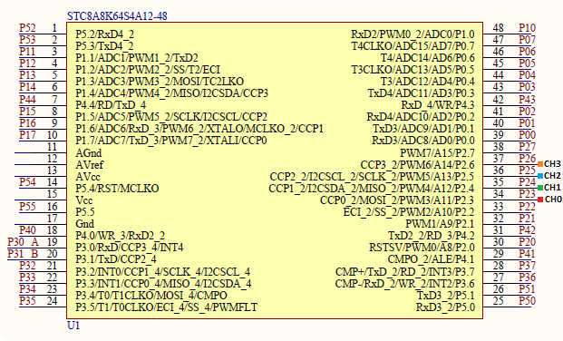
Pins P2.3 to P2.6 are used for PWM outputs. Each of these channels are set to 8-bit PWM mode and their compare and reload values are set to zero. Thus, initially all PWM channels are at same logic state. The PCA counter is set to run at system clock speed. All PWM channels will be running at same clock frequency as all are sharing the same PCA counter.
 PCA_pin_option(0x10);

 /*
 ECI         CCP0        CCP1      CCP2      CCP3        Hex            Option
 P1.2        P1.7        P1.6      P1.5      P1.4        0x00           option 1
 P2.2        P2.3        P2.4      P2.5      P2.6        0x10           option 2
 P7.4        P7.0        P7.1      P7.2      P7.3        0x20           option 3
 P3.5        P3.3        P3.2      P3.1      P3.0        0x30           option 4
 */


 PCA_setup(PCA_continue_counting_in_idle_mode, PCA_clk_sys_clk_div_1);

 PCA_n_PWM(0, PCA_PWM_without_interrupt, PCA_8_bit_PWM);
 PCA_n_PWM(1, PCA_PWM_without_interrupt, PCA_8_bit_PWM);
 PCA_n_PWM(2, PCA_PWM_without_interrupt, PCA_8_bit_PWM);
 PCA_n_PWM(3, PCA_PWM_without_interrupt, PCA_8_bit_PWM);

 PCA_0_8_bit_PWM_compare_value(0);
 PCA_0_8_bit_PWM_reload_value(0);

 PCA_1_8_bit_PWM_compare_value(0);
 PCA_1_8_bit_PWM_reload_value(0);

 PCA_2_8_bit_PWM_compare_value(0);
 PCA_2_8_bit_PWM_reload_value(0);

 PCA_3_8_bit_PWM_compare_value(0);
 PCA_3_8_bit_PWM_reload_value(0);

 PCA_load_counter(0);

 PCA_start_counter;
The PWM frequency of PCA channels is calculated to be as follows.
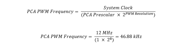
Thus, the period of the PWM is 21.33µs.
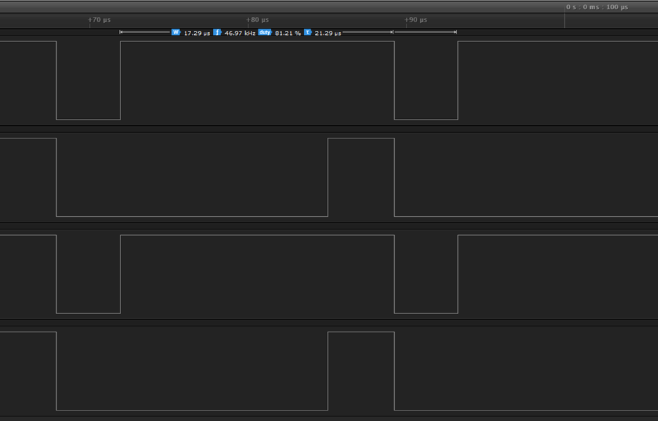
The logic analyser data confirms that the frequency is indeed around 46 kHz.
The duty cycles of the PWMs are calculated using the following formula.

Inside the main loop, each of the channels are updated every 10ms by updating their reload values.
 for(j = 0; j < 256; j++)
 {
   PCA_0_8_bit_PWM_reload_value(255 - j);
   PCA_1_8_bit_PWM_reload_value(j);
   PCA_2_8_bit_PWM_reload_value(255 - j);
   PCA_3_8_bit_PWM_reload_value(j);
   delay_ms(10);
 }

 for(j = 255; j > -1; j--)
 {
   PCA_0_8_bit_PWM_reload_value(255 - j);
   PCA_1_8_bit_PWM_reload_value(j);
   PCA_2_8_bit_PWM_reload_value(255 - j);
   PCA_3_8_bit_PWM_reload_value(j);
   delay_ms(10);
 }
Demo
|
|
hello.
this is a very good effort to document all and still share with us. thank you very much.
I have one doubt . which programming tool are you using ?
Hi, I am trying to understand the STC15w408as chip, and found this site after weeks of searching for something that sets the output of the GPIO pins to a different state. I have a the 28 pin stc15w and have connected it up with a FTDI board and can write to it using PlatformIO. The thing is, the GPIO ports if just switched on or do a reset they are in the HIGH state and I am trying to make them LOW when you do a reset.
Is your BSP code doing this and for what port or GPIO pin is it setting? I could change your P52 and P55 in your SETUP to the GPIO pins on my development board but not under standing the BSP Code.
Wonder if you get this post? but any help would be gratefully received.
Hi,
How Purchase the development board. Please,give the purchase link for this Development board.
https://www.alibaba.com/product-detail/Development-board-1T-STC8A8K64S4A12-single-chip_62391507065.html
https://world.taobao.com/item/600882463994.htm
https://www.amazon.ca/STC8A8K64S4A12-Development-Controller-Module-Minimal/dp/B08D3Y3R6T
How To read and write string data using IAP into memory
void IAP_erase(unsigned int address)
{
IAP_CONTR = 0x80; //?? IAP
IAP_TPS = 12;
// IAP_CONTR = IAP_WT;
IAP_CMD = IAP_erase_command;
IAP_address(address);
IAP_trigger;
_nop_();
_nop_();
_nop_();
IAP_clear;
}
void IAP_send_string(unsigned int uc_send_addr,unsigned char *uca_send_string,unsigned int uc_number_of_bytes)
{
unsigned int buff_cntr=0;
do
{
IAP_CONTR = 0x80; //?? ISP/IAP ??
IAP_TPS = (unsigned char)(11509200 / 1000000L); //??????
IAP_CMD = IAP_write_command;
// IAP_CMD = IAP_write_command;
IAP_ADDRH = uc_send_addr / 256; //??????(??????????????)
IAP_ADDRL = uc_send_addr % 256; //??????
IAP_DATA = uca_send_string[buff_cntr]; //???? ISP_DATA,????????????
IAP_trigger;//IAP_TRIG();
_nop_();
_nop_();
_nop_();
uc_send_addr++;
// uca_send_string++;
buff_cntr++;
IAP_clear;
delay_ms(8);
}while(–uc_number_of_bytes);
}
void IAP_read_string(unsigned int uc_read_addr,unsigned char *data_read,unsigned int uc_number_of_bytes)
{
unsigned int buff_cntr=0;
do{
IAP_CONTR = 0x80; //?? ISP/IAP ??
IAP_TPS = (unsigned char)(11059200 / 1000000L); //??????
IAP_CMD = IAP_read_command;
// IAP_CMD = IAP_read_command;
IAP_ADDRH = uc_read_addr / 256; //??????(??????????????)
IAP_ADDRL = uc_read_addr % 256; //??????
IAP_trigger;//IAP_TRIG(); //?? 5AH,?? A5H ? ISP/IAP ?????,
//???????
//?? A5H ?, ISP/IAP ?????????
//CPU ?? IAP ???,?????????
_nop_();
_nop_();
_nop_();
data_read[buff_cntr] = IAP_DATA; //???????
uc_read_addr++;
// data_read++;
buff_cntr++;
IAP_clear;
delay_ms(8);
}while(–uc_number_of_bytes);
}
stores only last byte to all bytes of flash memory sector… memory sector selected is 0xF600
Hi, I am using STC MCU since 10 years. Tech support is ZERO. but they are low cost, very stable. Now I have a problem when the chip that I used is obsolete. Now start to use STC8C2K64S4-28I-LQFP32 but no stc8Cxx.h file, I am using stc8Hxx.h file which compiles but in some stage freeze, the existing firmware. With stc8hxx.h file I can compile STC8F2K64S4-28I-LQFP32 and works not bad
.
I wrote them many times for the stc8Cxx.h file never got answer. Where Can I find that file?
Thank you
Give me detail 8f2k64s281MCU read and write programmer
Give me detail 8f2k64s281reed and write programmer distal
Hi. Can you explain how to use I2C in the slave mode ?
I tried STC8G1K08A i2c in slave mode. Doesn’t work (no response). It does not enter interrupt, even on a start condition (everything according to the code in the documentation). I also tried master mode – it works.
Thanks for these tutorials. I’m getting back into STCmicro coding now, having left them alone for the past several years. Back then I only used the STC89C52RC (and C54RD) but this time I’m also using the more powerful STC15 and STC8 types. Your blogs provide a wealth of useful information.
Hello,
You have done great job with all these tutorials. I am an electronics engineer trying to learn some new stuff. I am located in Greece , Europe and I would like to purchase the development board that you are using and download some datasheets in English if possible but I cannot find them anywhere. Could you please help me?
I suggest you buy from AliExpress or similar platform that is available in your country…. You can find the English datasheet here. English documentation can be found in STC’s official websites such as this one….
Thank you very much for your help!!!
i always get excited when you release new tutorials ,you are really doing a great job i wish i could write code and develop libraries like you.
Well, this is very nice and thorough tutorial indeed, many thanks!
Unfortunately I doubt there is good any reason to learn the STC platform beyond curiosity.
The STC 8051, although pretty evolved from the original 8051 ISA, does not offer anything crucial to justify the relatively high price of these micros and development tools along with certain cumbersomeness of this ancient platform.
They simply can not compete even with the legacy Cortex M0 in any way. I am even not aware about any affordable debugger/emulator for them.
All in all, I would never recommend anybody to start learning/using any 8051 without some very good reason to do so.