Exploring STC 8051 Microcontrollers – Coding

|
|
I2C
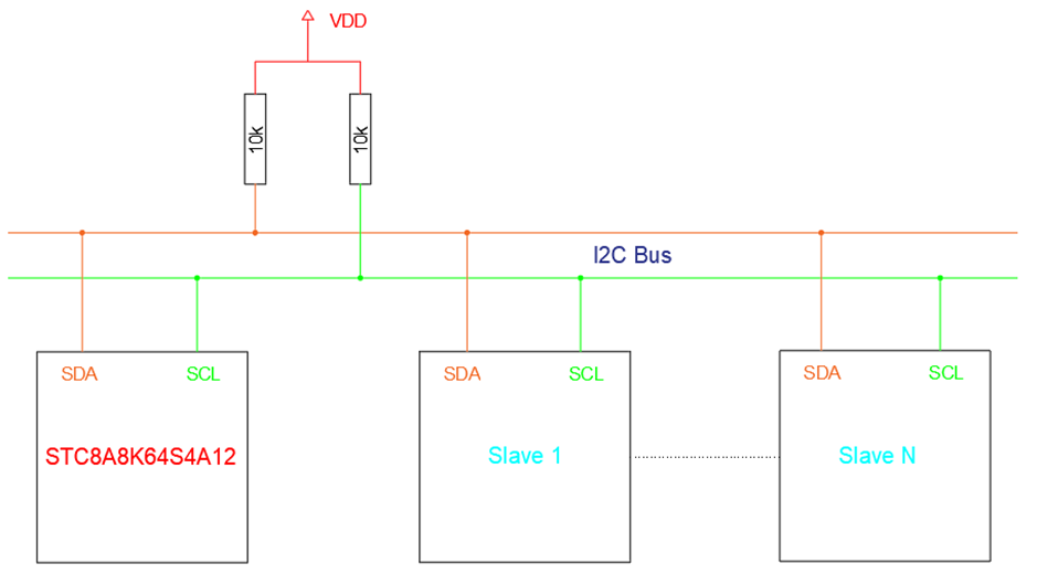
Inter Integrated Circuit (I2C) was pioneered by Philips (now NXP) about three decades ago. I2C, just like SPI, is meant for short-distance synchronous onboard communications. I2C is very simple to use as only two wires are needed for communication and this is why often I2C is alternatively called two-wire communication (TWI). In an I2C communication bus, there can be one master or host device and one or several slave devices. The maximum number of devices that can coexist in an I2C bus at a time is 127. Usually, the communication master or host is a microcontroller that is responsible for initiating communications while slave devices can be anything from another microcontroller to sensors, memory devices, digital peripherals, etc. Only master and slave data transactions are possible because only a master can request data from or write to a slave device. Slave-slave communication is not possible. In an I2C bus, only one master-slave pair can communicate at a time. The rest of the devices stay idle during this time.
To know more about I2C communication, visit these pages:
- https://learn.mikroe.com/i2c-everything-need-know
- https://learn.sparkfun.com/tutorials/i2c
- http://www.ti.com/lsds/ti/interface/i2c-overview.page
- http://www.robot-electronics.co.uk/i2c-tutorial
- https://www.i2c-bus.org/i2c-bus
- http://i2c.info
Code
I2C.h
 /*
 SCL         SDA         Hex            Option
 P1.5        P1.4        0x00           option 1
 P2.5        P2.4        0x10           option 2
 P7.7        P7.6        0x20           option 3
 P3.2        P3.3        0x30           option 4
 */

 #define I2C_pin_option(value)                          do{P_SW2 |= value;}while(0)

 //Timeout
 #define I2C_timeout                                   1000

 //state
 #define I2C_disable                                     0x00
 #define I2C_enable                                      0x80

 //mode
 #define I2C_slave_mode                                  0x00
 #define I2C_master_mode                                 0x40

 #define I2C_setup(state, mode, clk)                     do{ \
                                                             bit_set(P_SW2, 7); \
                                                             I2CCFG = (state | mode | (clk & 0x3F)); \
                                                             bit_clr(P_SW2, 7); \
                                                           }while(0)

 void I2C_wait(void)
 {
   unsigned int t = I2C_timeout;

   while((check_I2C_master_flag == FALSE) && (t > 0))
   {
     t--;
     delay_ms(1);
   };

   clear_I2C_master_flag;
 }

 void I2C_start(void)
 {
     bit_set(P_SW2, 7);
     I2CMSCR = 0x01;
     I2C_wait();
     bit_clr(P_SW2, 7);
 }

 void I2C_stop(void)
 {
     bit_set(P_SW2, 7);
     I2CMSCR = 0x06;
     I2C_wait();
     bit_clr(P_SW2, 7);
 }

 void I2C_write(unsigned char value)
 {
     bit_set(P_SW2, 7);
     I2CTXD = value;
     I2CMSCR = 0x02;
     I2C_wait();
     I2CMSCR = 0x03;
     I2C_wait();
     bit_clr(P_SW2, 7);
 }

 unsigned char I2C_read(unsigned char ACK_state)
 {
     unsigned char value = 0x00;

     bit_set(P_SW2, 7);
     I2CMSCR = 0x04;
     I2C_wait();
     value = I2CRXD;
     I2CMSST = ~ACK_state;
     I2CMSCR = 0x05;
     I2C_wait();
     bit_clr(P_SW2, 7);

     return value;
 }
DHT12.h
 #define I2C_W                               0x00
 #define I2C_R                               0x01

 #define no_of_bytes_to_read               0x05

 #define DHT12_I2C_address                  0xB8

 #define no_error                           0x00
 #define CRC_error                          0x01

 void DHT12_init(void);
 unsigned char DHT12_CRC(unsigned char *array_values);
 unsigned char DHT12_read_byte(unsigned char address);
 unsigned char DHT12_get_data(float *DHT12_RH, float *DHT12_T);
DHT12.c
 #include "DHT12.h"

 void DHT12_init(void)
 {
     I2C_pin_option(0x00);
     I2C_setup(I2C_enable, I2C_master_mode, 0xFF);
     delay_ms(100);
 }

 unsigned char DHT12_CRC(unsigned char *array_values)
 {
     signed char i = 0x03;
     unsigned char crc_result = 0x00;

     while(i > -1)
     {
         crc_result += array_values[i];
         i--;
     }

     return crc_result;
 }


 unsigned char DHT12_read_byte(unsigned char address)
 {
     unsigned char value = 0x00;

     I2C_start();
     I2C_write(DHT12_I2C_address);
     I2C_write(address);

     I2C_start();
     I2C_write(DHT12_I2C_address | I2C_R);
     value = I2C_read(0);
     I2C_stop();

     return value;
 }


 unsigned char DHT12_get_data(float *DHT12_RH, float *DHT12_T)
 {
     signed char i = no_of_bytes_to_read;

     unsigned char values[0x05] = {0x00, 0x00, 0x00, 0x00, 0x00};

     while(i > 0x00)
     {
         values[(no_of_bytes_to_read - i)] = DHT12_read_byte((no_of_bytes_to_read - i));
         i--;
     };

     if(values[0x04] == DHT12_CRC(values))
     {
         *DHT12_RH = (((float)values[0x00]) + (((float)values[0x01]) * 0.1));
         *DHT12_T = (((float)values[0x02]) + (((float)values[0x03]) * 0.1));

         return no_error;
     }

     else
     {
         return CRC_error;
     }
 }
main.c
 #include "STC8xxx.h"
 #include "BSP.h"
 #include "LCD.c"
 #include "lcd_print.c"
 #include "DHT12.c"

 void setup(void);

 void main(void)
 {
   unsigned char state = 0x00;

     float T = 0.0;
     float RH = 0.0;

     setup();

     LCD_goto(0, 0);
     LCD_putstr("R.H / %:");
     LCD_goto(0, 1);
     LCD_putstr("Temp/ C:");
     print_symbol(5, 1, 0);

     while(1)
     {
         state = DHT12_get_data(&RH, &T);

             switch(state)
             {
                 case no_error:
                 {
                     print_F(11, 0, RH, 1);
           print_F(11, 1, T, 1);
                     break;
                 }

                 default:
                 {
                     LCD_goto(12, 0);
                     LCD_putstr("--.-");
                     LCD_goto(12, 1);
                     LCD_putstr("--.-");
                 }
             }

             P55_toggle;
             delay_ms(400);
     };
 }

 void setup(void)
 {
   CLK_set_sys_clk(IRC_24M, 2, MCLK_SYSCLK_no_output, MCLK_out_P54);

   P55_open_drain_mode;

   LCD_init();
   LCD_clear_home();
   load_custom_symbol();

   DHT12_init();
 }
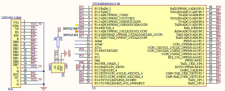
Schematic
Explanation
I2C.h header file describes how the I2C hardware will work. Firstly, I2C hardware pin pairs can be any of the following combinations:
 /*
 SCL         SDA         Hex            Option
 P1.5        P1.4        0x00           option 1
 P2.5        P2.4        0x10           option 2
 P7.7        P7.6        0x20           option 3
 P3.2        P3.3        0x30           option 4
 */

 #define I2C_pin_option(value)                           do{P_SW2 |= value;}while(0)
Secondly, we have the following I2C library functions that control I2C-related registers. Mainly, we would need these functions in order to properly use the I2C hardware. These the commonly used ones. Details of register handling can be avoided in this way.
 void I2C_start(void)
 void I2C_stop(void)
 void I2C_write(unsigned char value)
 unsigned char I2C_read(unsigned char ACK_state)
I have avoided interrupt-based I2C communication because I2C slave devices generally do not send out data without request from master device and master device only initiates data transaction when needed. There is no need to make things unnecessarily complicated.
Before using I2C hardware, we have to set it up and I2C_setup function exactly does that. It dictates mode of operation and I2C bus clock speed.
I2C_setup(I2C_enable, I2C_master_mode, 0xFF);
For demoing I2C communication, Aosong’s DHT12 relative humidity-temperature sensor is used. This device is pretty simple to use.
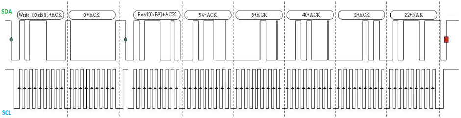
The timing diagram shown above depicts that the entire sequence of data transfer is a typical I2C read. However, to simplify the task of reading the sensor, I coded the read function to read the I2C bus in byte format rather than in word format. The reading process is a usual I2C read.
 unsigned char DHT12_read_byte(unsigned char address)
 {
     unsigned char value = 0x00;

     I2C_start();
     I2C_write(DHT12_I2C_address);
     I2C_write(address);

     I2C_start();
     I2C_write(DHT12_I2C_address | I2C_R);
     value = I2C_read(0);
     I2C_stop();

     return value;
 }
Since we have to take care of Cyclic Redundancy Check (CRC) in order to ensure data integrity several byte reads are done and the read data are stored in an array. The array consists of two bytes of relative humidity data followed by two bytes of temperature data and a CRC byte – five bytes in total. After getting all the values from the sensor, CRC check is performed. If there is no CRC error, the temperature and relative humidity data are processed or else CRC error is flagged.
 unsigned char DHT12_get_data(float *DHT12_RH, float *DHT12_T)
 {
     signed char i = no_of_bytes_to_read;
     unsigned char values[0x05] = {0x00, 0x00, 0x00, 0x00, 0x00};

     while(i > 0x00)
     {
         values[(no_of_bytes_to_read - i)] = DHT12_read_byte((no_of_bytes_to_read - i));
         i--;
     };

     if(values[0x04] == DHT12_CRC(values))
     {
         *DHT12_RH = (((float)values[0x00]) + (((float)values[0x01]) * 0.1));
         *DHT12_T = (((float)values[0x02]) + (((float)values[0x03]) * 0.1));

         return no_error;
     }
     else
     {
         return CRC_error;
     }
 }
DH12’s CRC check is straight-forward. The temperature and humidity bytes are summed up and checked against the sent-out CRC value. If the values are same then there is no error in sent data.
 unsigned char DHT12_CRC(unsigned char *array_values)
 {
     signed char i = 0x03;
     unsigned char crc_result = 0x00;

     while(i > -1)
     {
         crc_result += array_values[i];
         i--;
     }

     return crc_result;
 }
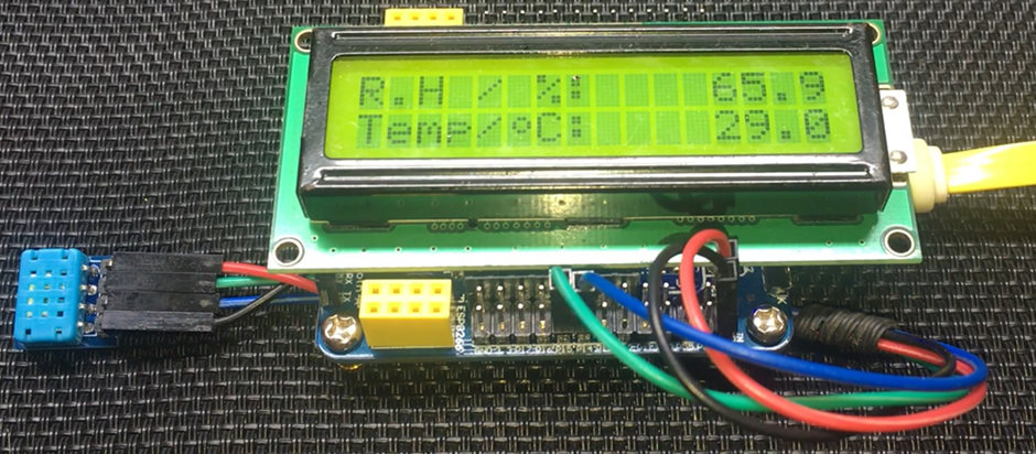
In the main, the sensor is read and the temperature-relative humidity data are displayed on an LCD display.
Demo
|
|
hello.
this is a very good effort to document all and still share with us. thank you very much.
I have one doubt . which programming tool are you using ?
Hi, I am trying to understand the STC15w408as chip, and found this site after weeks of searching for something that sets the output of the GPIO pins to a different state. I have a the 28 pin stc15w and have connected it up with a FTDI board and can write to it using PlatformIO. The thing is, the GPIO ports if just switched on or do a reset they are in the HIGH state and I am trying to make them LOW when you do a reset.
Is your BSP code doing this and for what port or GPIO pin is it setting? I could change your P52 and P55 in your SETUP to the GPIO pins on my development board but not under standing the BSP Code.
Wonder if you get this post? but any help would be gratefully received.
Hi,
How Purchase the development board. Please,give the purchase link for this Development board.
https://www.alibaba.com/product-detail/Development-board-1T-STC8A8K64S4A12-single-chip_62391507065.html
https://world.taobao.com/item/600882463994.htm
https://www.amazon.ca/STC8A8K64S4A12-Development-Controller-Module-Minimal/dp/B08D3Y3R6T
How To read and write string data using IAP into memory
void IAP_erase(unsigned int address)
{
IAP_CONTR = 0x80; //?? IAP
IAP_TPS = 12;
// IAP_CONTR = IAP_WT;
IAP_CMD = IAP_erase_command;
IAP_address(address);
IAP_trigger;
_nop_();
_nop_();
_nop_();
IAP_clear;
}
void IAP_send_string(unsigned int uc_send_addr,unsigned char *uca_send_string,unsigned int uc_number_of_bytes)
{
unsigned int buff_cntr=0;
do
{
IAP_CONTR = 0x80; //?? ISP/IAP ??
IAP_TPS = (unsigned char)(11509200 / 1000000L); //??????
IAP_CMD = IAP_write_command;
// IAP_CMD = IAP_write_command;
IAP_ADDRH = uc_send_addr / 256; //??????(??????????????)
IAP_ADDRL = uc_send_addr % 256; //??????
IAP_DATA = uca_send_string[buff_cntr]; //???? ISP_DATA,????????????
IAP_trigger;//IAP_TRIG();
_nop_();
_nop_();
_nop_();
uc_send_addr++;
// uca_send_string++;
buff_cntr++;
IAP_clear;
delay_ms(8);
}while(–uc_number_of_bytes);
}
void IAP_read_string(unsigned int uc_read_addr,unsigned char *data_read,unsigned int uc_number_of_bytes)
{
unsigned int buff_cntr=0;
do{
IAP_CONTR = 0x80; //?? ISP/IAP ??
IAP_TPS = (unsigned char)(11059200 / 1000000L); //??????
IAP_CMD = IAP_read_command;
// IAP_CMD = IAP_read_command;
IAP_ADDRH = uc_read_addr / 256; //??????(??????????????)
IAP_ADDRL = uc_read_addr % 256; //??????
IAP_trigger;//IAP_TRIG(); //?? 5AH,?? A5H ? ISP/IAP ?????,
//???????
//?? A5H ?, ISP/IAP ?????????
//CPU ?? IAP ???,?????????
_nop_();
_nop_();
_nop_();
data_read[buff_cntr] = IAP_DATA; //???????
uc_read_addr++;
// data_read++;
buff_cntr++;
IAP_clear;
delay_ms(8);
}while(–uc_number_of_bytes);
}
stores only last byte to all bytes of flash memory sector… memory sector selected is 0xF600
Hi, I am using STC MCU since 10 years. Tech support is ZERO. but they are low cost, very stable. Now I have a problem when the chip that I used is obsolete. Now start to use STC8C2K64S4-28I-LQFP32 but no stc8Cxx.h file, I am using stc8Hxx.h file which compiles but in some stage freeze, the existing firmware. With stc8hxx.h file I can compile STC8F2K64S4-28I-LQFP32 and works not bad
.
I wrote them many times for the stc8Cxx.h file never got answer. Where Can I find that file?
Thank you
Give me detail 8f2k64s281MCU read and write programmer
Give me detail 8f2k64s281reed and write programmer distal
Hi. Can you explain how to use I2C in the slave mode ?
I tried STC8G1K08A i2c in slave mode. Doesn’t work (no response). It does not enter interrupt, even on a start condition (everything according to the code in the documentation). I also tried master mode – it works.
Thanks for these tutorials. I’m getting back into STCmicro coding now, having left them alone for the past several years. Back then I only used the STC89C52RC (and C54RD) but this time I’m also using the more powerful STC15 and STC8 types. Your blogs provide a wealth of useful information.
Hello,
You have done great job with all these tutorials. I am an electronics engineer trying to learn some new stuff. I am located in Greece , Europe and I would like to purchase the development board that you are using and download some datasheets in English if possible but I cannot find them anywhere. Could you please help me?
I suggest you buy from AliExpress or similar platform that is available in your country…. You can find the English datasheet here. English documentation can be found in STC’s official websites such as this one….
Thank you very much for your help!!!
i always get excited when you release new tutorials ,you are really doing a great job i wish i could write code and develop libraries like you.
Well, this is very nice and thorough tutorial indeed, many thanks!
Unfortunately I doubt there is good any reason to learn the STC platform beyond curiosity.
The STC 8051, although pretty evolved from the original 8051 ISA, does not offer anything crucial to justify the relatively high price of these micros and development tools along with certain cumbersomeness of this ancient platform.
They simply can not compete even with the legacy Cortex M0 in any way. I am even not aware about any affordable debugger/emulator for them.
All in all, I would never recommend anybody to start learning/using any 8051 without some very good reason to do so.