Exploring STC 8051 Microcontrollers – Coding

|
|
UART
Serial communication is probably the most widely used communication method. It is simple to implement and can be used to communicate with a computer literally directly without needing too many extra external hardware. Serial communication also has the distance advantage over other communication interfaces. Serial communication can be implemented using UART hardware peripherals of STC micros. Many sensors, communication devices like GSM modems and RF devices, RFIDs and other external devices use this simple and time-proven interface for communicating with host micros. UART is also the backbone of other communication methods like MODBUS, IrDA, LIN, etc.
To learn more about UART visit the following link:
https://learn.mikroe.com/uart-serial-communication
Code
 #include "STC8xxx.h"
 #include "BSP.h"
 #include "LCD.c"
 #include "lcd_print.c"

 void setup(void);

 void main(void)
 {
   unsigned char msg1[10] = {"MicroArena"};
   unsigned char msg2[10] = {"SShahryiar"};

   char i = 0x00;

   char rcv_1 = 0x00;
   char rcv_4 = 0x00;

   setup();

   LCD_goto(0, 0);
   LCD_putstr("TXD1: ");
   LCD_goto(10, 0);
   LCD_putstr("RXD1: ");

   LCD_goto(0, 1);
   LCD_putstr("TXD4: ");
   LCD_goto(10, 1);
   LCD_putstr("RXD4: ");

   while(1)
   {
     for(i = 0; i < 10; i++)
     {
       UART1_write_buffer(msg1[i]);
       UART4_write_buffer(msg2[i]);

       LCD_goto(5, 0);
       LCD_putchar(msg1[i]);
       LCD_goto(5, 1);
       LCD_putchar(msg2[i]);

       rcv_1 = UART1_read_buffer();
       rcv_4 = UART4_read_buffer();

       LCD_goto(15, 0);
       LCD_putchar(rcv_1);
       LCD_goto(15, 1);
       LCD_putchar(rcv_4);

       delay_ms(900);
     }
   };
 }

 void setup(void)
 {
   CLK_set_sys_clk(IRC_24M, 2, MCLK_SYSCLK_no_output, MCLK_out_P54);

   UART1_pin_option(0xC0);
   UART1_init(9600, \
              UART1_baud_source_TMR2, \
              UART1_timer_12T, \
              12000000);

   UART4_pin_option(0x04);
   UART4_init(9600, \
              UART4_baud_source_TMR4, \
              UART4_timer_1T, \
              12000000);

   LCD_init();
   LCD_clear_home();
 }
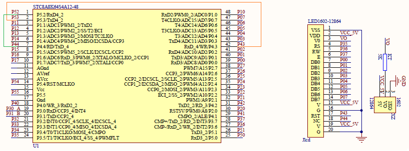
Schematic
Explanation
STC8A8K64S4A12 has four hardware UART peripherals. Of these four, UART1 has some advanced features that are rarely needed. The rest are pretty much alike. Like other communication hardware peripherals, pin configuration must be selected as alternative pin arrangements are available.
 /*
 RXD         TXD         Hex            Option
 P0.2        P0.3        0x00           option 1
 P5.2        P5.3        0x04           option 2
 */

 #define UART4_pin_option(value)        do{P_SW2 |= value;}while(0)
UART, although asynchronous, need to transmit and receive data in timed-frame formats and so when two UART devices need to communicate with each other, they must negotiate a mutually agreed baud rate or else data will not recognized. It is like tuning to the right radio station for listening the music channel that we want to listen. Thus, baud rate generation is a very crucial part of UART peripheral. For baud rate generation, UARTs can either use Timer 2 or other timer having the same number as the UART itself, for example, in the case of UART3, only Timer 2 and Timer 3 can be used as baud rate generator. I personally recommend that we keep Timer 2 reserved for other applications or UART2 and use other timers independently as to avoid conflicts in different UART hardware. Yes, I know it contradicts with my past statement of keeping Timer 2 reserved for UART applications but what else can be done when multiple UARTs are used in an application. BSP functions take care of everything internally and so we can focus on coding.
The system clock is set to 12MHz. This is very important because timers are responsible for baud rate generation and are dependent on system clock.
CLK_set_sys_clk(IRC_24M, 2, MCLK_SYSCLK_no_output, MCLK_out_P54);
To setup UART, we need to specify baud rate, clock source of baud rate generator, i.e., the timer to be used, its prescale factor and system clock speed in hertz.
 UART4_init(9600, \
            UART4_baud_source_TMR4, \
            UART4_timer_1T, \
            12000000);
UART reading and writing is done as shown below.
 UART4_write_buffer(msg2[i]);
 ....
 rcv_4 = UART4_read_buffer();
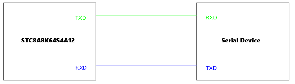
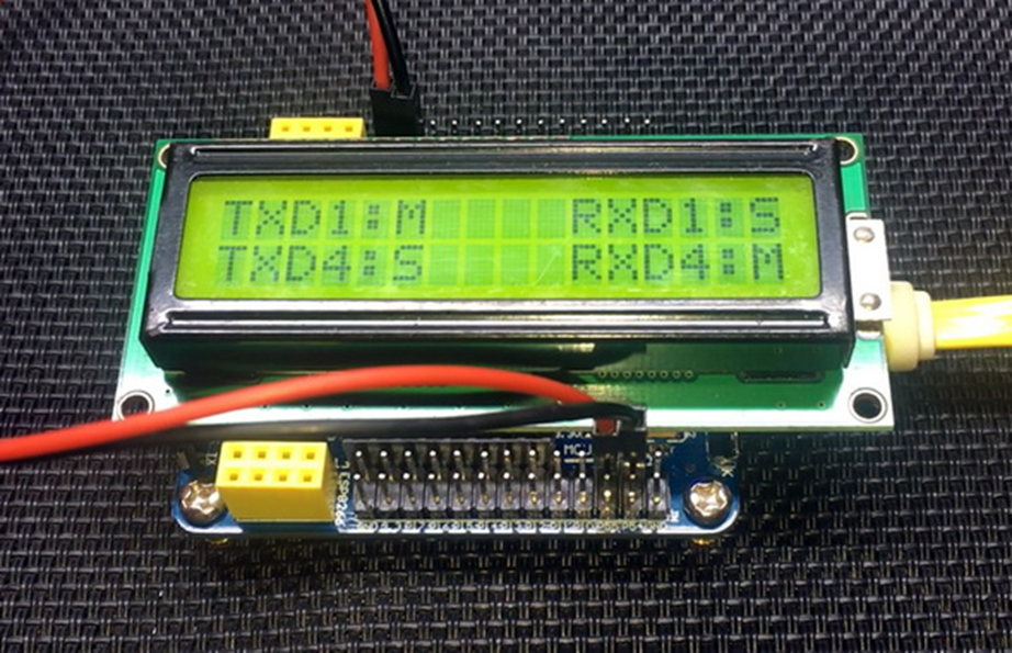
The demo here uses two built-in UARTs – UART1 and UART4, crisscrossed among themselves. Each transmitting and receiving the other’s message. Whatever each is sending and receiving is also shown on an LCD display.
Demo
|
|
hello.
this is a very good effort to document all and still share with us. thank you very much.
I have one doubt . which programming tool are you using ?
Hi, I am trying to understand the STC15w408as chip, and found this site after weeks of searching for something that sets the output of the GPIO pins to a different state. I have a the 28 pin stc15w and have connected it up with a FTDI board and can write to it using PlatformIO. The thing is, the GPIO ports if just switched on or do a reset they are in the HIGH state and I am trying to make them LOW when you do a reset.
Is your BSP code doing this and for what port or GPIO pin is it setting? I could change your P52 and P55 in your SETUP to the GPIO pins on my development board but not under standing the BSP Code.
Wonder if you get this post? but any help would be gratefully received.
Hi,
How Purchase the development board. Please,give the purchase link for this Development board.
https://www.alibaba.com/product-detail/Development-board-1T-STC8A8K64S4A12-single-chip_62391507065.html
https://world.taobao.com/item/600882463994.htm
https://www.amazon.ca/STC8A8K64S4A12-Development-Controller-Module-Minimal/dp/B08D3Y3R6T
How To read and write string data using IAP into memory
void IAP_erase(unsigned int address)
{
IAP_CONTR = 0x80; //?? IAP
IAP_TPS = 12;
// IAP_CONTR = IAP_WT;
IAP_CMD = IAP_erase_command;
IAP_address(address);
IAP_trigger;
_nop_();
_nop_();
_nop_();
IAP_clear;
}
void IAP_send_string(unsigned int uc_send_addr,unsigned char *uca_send_string,unsigned int uc_number_of_bytes)
{
unsigned int buff_cntr=0;
do
{
IAP_CONTR = 0x80; //?? ISP/IAP ??
IAP_TPS = (unsigned char)(11509200 / 1000000L); //??????
IAP_CMD = IAP_write_command;
// IAP_CMD = IAP_write_command;
IAP_ADDRH = uc_send_addr / 256; //??????(??????????????)
IAP_ADDRL = uc_send_addr % 256; //??????
IAP_DATA = uca_send_string[buff_cntr]; //???? ISP_DATA,????????????
IAP_trigger;//IAP_TRIG();
_nop_();
_nop_();
_nop_();
uc_send_addr++;
// uca_send_string++;
buff_cntr++;
IAP_clear;
delay_ms(8);
}while(–uc_number_of_bytes);
}
void IAP_read_string(unsigned int uc_read_addr,unsigned char *data_read,unsigned int uc_number_of_bytes)
{
unsigned int buff_cntr=0;
do{
IAP_CONTR = 0x80; //?? ISP/IAP ??
IAP_TPS = (unsigned char)(11059200 / 1000000L); //??????
IAP_CMD = IAP_read_command;
// IAP_CMD = IAP_read_command;
IAP_ADDRH = uc_read_addr / 256; //??????(??????????????)
IAP_ADDRL = uc_read_addr % 256; //??????
IAP_trigger;//IAP_TRIG(); //?? 5AH,?? A5H ? ISP/IAP ?????,
//???????
//?? A5H ?, ISP/IAP ?????????
//CPU ?? IAP ???,?????????
_nop_();
_nop_();
_nop_();
data_read[buff_cntr] = IAP_DATA; //???????
uc_read_addr++;
// data_read++;
buff_cntr++;
IAP_clear;
delay_ms(8);
}while(–uc_number_of_bytes);
}
stores only last byte to all bytes of flash memory sector… memory sector selected is 0xF600
Hi, I am using STC MCU since 10 years. Tech support is ZERO. but they are low cost, very stable. Now I have a problem when the chip that I used is obsolete. Now start to use STC8C2K64S4-28I-LQFP32 but no stc8Cxx.h file, I am using stc8Hxx.h file which compiles but in some stage freeze, the existing firmware. With stc8hxx.h file I can compile STC8F2K64S4-28I-LQFP32 and works not bad
.
I wrote them many times for the stc8Cxx.h file never got answer. Where Can I find that file?
Thank you
Give me detail 8f2k64s281MCU read and write programmer
Give me detail 8f2k64s281reed and write programmer distal
Hi. Can you explain how to use I2C in the slave mode ?
I tried STC8G1K08A i2c in slave mode. Doesn’t work (no response). It does not enter interrupt, even on a start condition (everything according to the code in the documentation). I also tried master mode – it works.
Thanks for these tutorials. I’m getting back into STCmicro coding now, having left them alone for the past several years. Back then I only used the STC89C52RC (and C54RD) but this time I’m also using the more powerful STC15 and STC8 types. Your blogs provide a wealth of useful information.
Hello,
You have done great job with all these tutorials. I am an electronics engineer trying to learn some new stuff. I am located in Greece , Europe and I would like to purchase the development board that you are using and download some datasheets in English if possible but I cannot find them anywhere. Could you please help me?
I suggest you buy from AliExpress or similar platform that is available in your country…. You can find the English datasheet here. English documentation can be found in STC’s official websites such as this one….
Thank you very much for your help!!!
i always get excited when you release new tutorials ,you are really doing a great job i wish i could write code and develop libraries like you.
Well, this is very nice and thorough tutorial indeed, many thanks!
Unfortunately I doubt there is good any reason to learn the STC platform beyond curiosity.
The STC 8051, although pretty evolved from the original 8051 ISA, does not offer anything crucial to justify the relatively high price of these micros and development tools along with certain cumbersomeness of this ancient platform.
They simply can not compete even with the legacy Cortex M0 in any way. I am even not aware about any affordable debugger/emulator for them.
All in all, I would never recommend anybody to start learning/using any 8051 without some very good reason to do so.