Exploring STC 8051 Microcontrollers – Coding

|
|
Timing-Related Hardware Overview
When it comes to timer-counters and time-related hardware, STC microcontrollers pack lot of punch. There are five 16-bit timer-counters, a Programmable Counter Array (PCA) and an enhanced PWM hardware peripheral. The timers are similar to the timers of standard 8051 microcontrollers. The rest of the hardware peripherals are bonus features that are not typically available in traditional 8051s.
Timer-Counters
Timer-Counters T0 – T4 are the five 16-bit timer-counters. As with the timers of any MCU, timers of STC microcontrollers can be employed for a number of tasks including time-base, timing events and outputs, measuring intervals, etc. Timers of 8051 architecture-based microcontrollers are usually also responsible for internal serial port (UART) hardware baud-rate generations and so is the case with STC microcontrollers. Thus, these timers are very versatile.
The typical structure of timers of traditional 8051s looks like the block diagram shown below but it is not completely the same for STC microcontrollers.
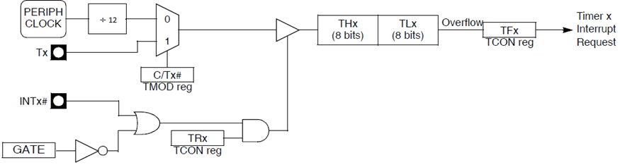
THx and TLx are cascaded counters that can be clocked using internal peripheral clock or externally via specific timer input GPIO pins. The clock that would drive the counters can be optionally scaled but unlike other microcontrollers the scaling is restricted to 1T or 12T, i.e., the driving source clock is either divided by one or divided by a factor of 12. When a timer is internally clocked, it is said to be acting like a timer and when it is clocked externally, it is said to be operating as a counter. All timers have interrupt capabilities and always count to top value from either 0 or some predefined value. Timers T0 and T1 are special timers while the rest are general purpose timers.
The timers can be operated in the following modes of operations:
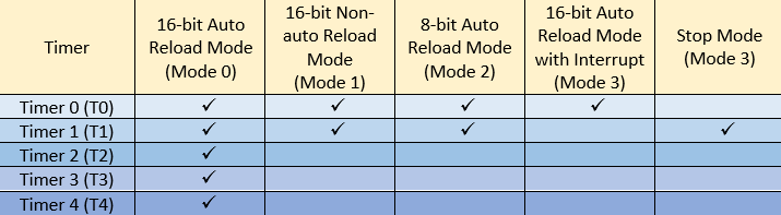
These modes of operations have similarities with standard 8051s but there are also some minor differences.
- 16-bit Auto Reload Mode (Mode 0)
In auto-reload mode, a timer’s internal counter (TLx and THx) is loaded with some user-defined value at the beginning and the timer is started. It will count from that set value to the top value of 65535 (0xFFFF) and then overflow. After the overflow event, the user-defined value is automatically reloaded to the timer’s counter and the process repeats. The overflow event can generate an interrupt.
- 16-bit Non-auto Reload Mode (Mode 1)
Mode 1 is same as Mode 0 but the only difference between them is reloading feature. In Mode 1, a timer’s internal counter (TLx and THx) needs to be reloaded manually through coding.
- 8-bit Auto Reload Mode (Mode 2)
Mode 2 is similar to Mode 0. The differences are resolution and how the timer is reloaded. In this mode, TLx is used as counter and THx is used as the buffer that with reload TLx when overflow occurs.
- 16-bit Auto Reload Mode with Interrupt (Mode 3)
This mode is same as Mode 0 but in this mode, interrupt cannot be disabled. In Mode 0, we have the option to either use timer interrupt or have it disabled.
- Stop Mode
Stop mode is only valid for Timer 1. Actually, all timers can be stopped somehow but entering this mode will disable Timer 1.
Enhanced PWM Module
The enhanced PWM module of STC8A8K64S4A12 provides 8 channel 15-bit PWM outputs. This module allows lot of advanced PWM features like complementary PWMs with dead-times, PWMs with initial level settings, etc. There are options to use this module with internal ADC and there are options to detect faults. This module is best suited for power control applications like inverters, battery chargers, switch-mode power supplies (SMPS), etc. Lastly, this module can operate independently without the need of help from other internal timer modules.
Programmable Counter Array (PCA)
STC8A8K64S4A12’s programmable array counter is an interesting and rare hardware peripheral. PCA is not seen in most microcontrollers. PCA basically extends PWM capabilities of STC8A8K64S4A12 while including input capture peripherals, special outputs and robust interrupt capabilities. PCA-based PWMs are of either 6-bit, 7-bit, 8-bit and 10-bit resolution and can be considered as general-purpose PWMs. The PCA module can be considered as an additional built-in timer peripheral as it can operate independently just like the PWM module.
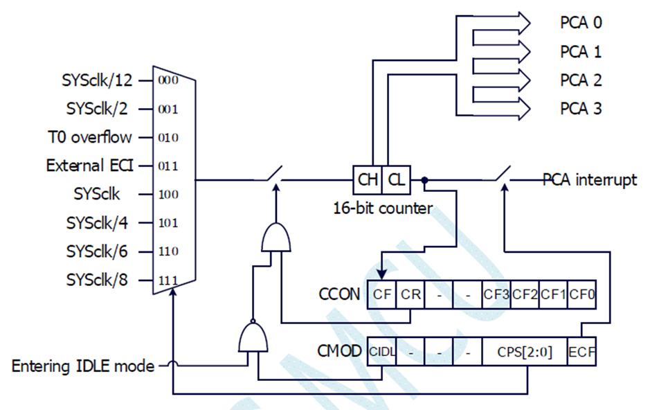
In STC8A8K64S4A12, there are four PCA groups – CCP0, CCP1, CCP2 and CCP3 that are dependent on a central 16-bit counter and configuration assets. CCP0, CCP1, CCP2 and CCP3 can be inputs or outputs depending on the mode of operation of PCA module itself. The counter can be clocked with a number of clock sources as shown in the block diagram.
Other Timers
Apart from all aforementioned peripherals, STC8A8K64S4A12 packs a wakeup timer and a watchdog timer. Wakeup timer can bring out a STC8A8K64S4A12 micro from low power sleep mode after fixed time intervals. Watchdog timer in STC8A8K64S4A12 is just like the watchdog timer of any other microcontroller and is mainly intended for resetting should there be an unforeseen software loop/error. These timers do not have alternative usage.
|
|
hello.
this is a very good effort to document all and still share with us. thank you very much.
I have one doubt . which programming tool are you using ?
Hi, I am trying to understand the STC15w408as chip, and found this site after weeks of searching for something that sets the output of the GPIO pins to a different state. I have a the 28 pin stc15w and have connected it up with a FTDI board and can write to it using PlatformIO. The thing is, the GPIO ports if just switched on or do a reset they are in the HIGH state and I am trying to make them LOW when you do a reset.
Is your BSP code doing this and for what port or GPIO pin is it setting? I could change your P52 and P55 in your SETUP to the GPIO pins on my development board but not under standing the BSP Code.
Wonder if you get this post? but any help would be gratefully received.
Hi,
How Purchase the development board. Please,give the purchase link for this Development board.
https://www.alibaba.com/product-detail/Development-board-1T-STC8A8K64S4A12-single-chip_62391507065.html
https://world.taobao.com/item/600882463994.htm
https://www.amazon.ca/STC8A8K64S4A12-Development-Controller-Module-Minimal/dp/B08D3Y3R6T
How To read and write string data using IAP into memory
void IAP_erase(unsigned int address)
{
IAP_CONTR = 0x80; //?? IAP
IAP_TPS = 12;
// IAP_CONTR = IAP_WT;
IAP_CMD = IAP_erase_command;
IAP_address(address);
IAP_trigger;
_nop_();
_nop_();
_nop_();
IAP_clear;
}
void IAP_send_string(unsigned int uc_send_addr,unsigned char *uca_send_string,unsigned int uc_number_of_bytes)
{
unsigned int buff_cntr=0;
do
{
IAP_CONTR = 0x80; //?? ISP/IAP ??
IAP_TPS = (unsigned char)(11509200 / 1000000L); //??????
IAP_CMD = IAP_write_command;
// IAP_CMD = IAP_write_command;
IAP_ADDRH = uc_send_addr / 256; //??????(??????????????)
IAP_ADDRL = uc_send_addr % 256; //??????
IAP_DATA = uca_send_string[buff_cntr]; //???? ISP_DATA,????????????
IAP_trigger;//IAP_TRIG();
_nop_();
_nop_();
_nop_();
uc_send_addr++;
// uca_send_string++;
buff_cntr++;
IAP_clear;
delay_ms(8);
}while(–uc_number_of_bytes);
}
void IAP_read_string(unsigned int uc_read_addr,unsigned char *data_read,unsigned int uc_number_of_bytes)
{
unsigned int buff_cntr=0;
do{
IAP_CONTR = 0x80; //?? ISP/IAP ??
IAP_TPS = (unsigned char)(11059200 / 1000000L); //??????
IAP_CMD = IAP_read_command;
// IAP_CMD = IAP_read_command;
IAP_ADDRH = uc_read_addr / 256; //??????(??????????????)
IAP_ADDRL = uc_read_addr % 256; //??????
IAP_trigger;//IAP_TRIG(); //?? 5AH,?? A5H ? ISP/IAP ?????,
//???????
//?? A5H ?, ISP/IAP ?????????
//CPU ?? IAP ???,?????????
_nop_();
_nop_();
_nop_();
data_read[buff_cntr] = IAP_DATA; //???????
uc_read_addr++;
// data_read++;
buff_cntr++;
IAP_clear;
delay_ms(8);
}while(–uc_number_of_bytes);
}
stores only last byte to all bytes of flash memory sector… memory sector selected is 0xF600
Hi, I am using STC MCU since 10 years. Tech support is ZERO. but they are low cost, very stable. Now I have a problem when the chip that I used is obsolete. Now start to use STC8C2K64S4-28I-LQFP32 but no stc8Cxx.h file, I am using stc8Hxx.h file which compiles but in some stage freeze, the existing firmware. With stc8hxx.h file I can compile STC8F2K64S4-28I-LQFP32 and works not bad
.
I wrote them many times for the stc8Cxx.h file never got answer. Where Can I find that file?
Thank you
Give me detail 8f2k64s281MCU read and write programmer
Give me detail 8f2k64s281reed and write programmer distal
Hi. Can you explain how to use I2C in the slave mode ?
I tried STC8G1K08A i2c in slave mode. Doesn’t work (no response). It does not enter interrupt, even on a start condition (everything according to the code in the documentation). I also tried master mode – it works.
Thanks for these tutorials. I’m getting back into STCmicro coding now, having left them alone for the past several years. Back then I only used the STC89C52RC (and C54RD) but this time I’m also using the more powerful STC15 and STC8 types. Your blogs provide a wealth of useful information.
Hello,
You have done great job with all these tutorials. I am an electronics engineer trying to learn some new stuff. I am located in Greece , Europe and I would like to purchase the development board that you are using and download some datasheets in English if possible but I cannot find them anywhere. Could you please help me?
I suggest you buy from AliExpress or similar platform that is available in your country…. You can find the English datasheet here. English documentation can be found in STC’s official websites such as this one….
Thank you very much for your help!!!
i always get excited when you release new tutorials ,you are really doing a great job i wish i could write code and develop libraries like you.
Well, this is very nice and thorough tutorial indeed, many thanks!
Unfortunately I doubt there is good any reason to learn the STC platform beyond curiosity.
The STC 8051, although pretty evolved from the original 8051 ISA, does not offer anything crucial to justify the relatively high price of these micros and development tools along with certain cumbersomeness of this ancient platform.
They simply can not compete even with the legacy Cortex M0 in any way. I am even not aware about any affordable debugger/emulator for them.
All in all, I would never recommend anybody to start learning/using any 8051 without some very good reason to do so.