Exploring STC 8051 Microcontrollers – Coding

|
|
Using Timer 2 to Multiplex Seven Segment Displays
Rather than polling, a better way to use timers is to use their interrupts. Timer overflow interrupt is particularly useful for timing event accurately. Timer overflow interrupt will periodically interrupt main tasks and can perform certain things inside the interrupt and then get back to main tasks. In this way, several tasks will apparently seem to occur concurrently. Multiplexing seven segment displays is one such example. These displays need periodic scanning, multiplexing and updating. If these tasks are done swiftly and in short duration, human eyes can be tricked. If a CPU is occupied doing these tasks alone then it would not be able to do other tasks. If the tasks of seven segment displays are put inside a timer interrupt, the CPU can do other tasks in other interrupts and main code as seven segment displays need only periodic attention and not all code processing is spent on the displays alone.
Code
 #include "STC8xxx.h"
 #include "BSP.h"

 #define DAT_pin_HIGH                    P41_high
 #define DAT_pin_LOW                     P41_low

 #define CLK_pin_HIGH                    P42_high
 #define CLK_pin_LOW                     P42_low

 #define refresh_time_in_us              315
 #define max_tmr_cnt                     0xFFFF
 #define tmr_val                         (max_tmr_cnt - refresh_time_in_us)

 const unsigned char pos[0x08] =
 {
     0x01, 0x02, 0x04, 0x08, 0x10, 0x20, 0x40, 0x80
 };

 const unsigned char num[0x0A] =
 {
     0x03, 0x9F, 0x25, 0x0D, 0x99, 0x49, 0x41, 0x1F, 0x01, 0x09
 };

 unsigned char i = 0x00;

 signed int value_1 = 0;
 signed int value_2 = 0;

 void setup(void);
 void Write_74HC164(unsigned char val, unsigned char seg);

 void ADC_ISR(void)
 interrupt 5
 {
   value_1 = ((ADC_RES << 8) | ADC_RESL);
   value_2 = ((value_1 * 5000.0) / 4096.0);
   clear_ADC_flag;
 }

 void TMR_2_ISR(void)
 interrupt 12
 {
     switch(i)
     {
         case 0:
         {
             Write_74HC164(num[(value_1 / 1000)], pos[3]);
             break;
         }

         case 1:
         {
             Write_74HC164((num[((value_1 % 1000) / 100)]), pos[2]);
             break;
         }

         case 2:
         {
             Write_74HC164(num[((value_1 % 100) / 10)], pos[1]);
             break;
         }

         case 3:
         {
             Write_74HC164(num[(value_1 % 10)], pos[0]);
             break;
         }

         case 4:
         {
             Write_74HC164(num[(value_2 / 1000)] & 0xFE, pos[7]);
             break;
         }

         case 5:
         {
             Write_74HC164((num[((value_2 % 1000) / 100)]), pos[6]);
             break;
         }

         case 6:
         {
             Write_74HC164(num[((value_2 % 100) / 10)], pos[5]);
             break;
         }

         case 7:
         {
             Write_74HC164(num[(value_2 % 10)], pos[4]);
             break;
         }
     }

     i++;

     if(i >= 8)
     {
         i = 0;
     }
     clear_TMR_2_overflow_flag;
 }

 void main(void)
 {
   setup();

     while(1)
     {
         ADC_set_channel(CH15);
         delay_ms(10);
         ADC_start_conversion;
         delay_ms(400);
     };
 }

 void setup(void)
 {
   CLK_set_sys_clk(IRC_24M, 2, MCLK_SYSCLK_no_output, MCLK_out_P54);

   P41_push_pull_mode;
   P42_push_pull_mode;

   ADC_enable;
   ADC_result_format_right_aligned;
   ADC_set_conversion_speed(ADC_conv_128_CLKs);
   _enable_ADC_interrupt;

   TMR2_setup(TMR2_sysclk, TMR2_clk_prescalar_12T);
   TMR2_load_counter_16(tmr_val);
   TMR2_start;
   _enable_TMR_2_interrupt;
   _enable_global_interrupt;
 }
 void Write_74HC164(unsigned char val, unsigned char seg)
 {
     unsigned char s = 0x10;
     unsigned int temp = 0x0000;

     temp = (unsigned int)seg;
     temp <<= 8;
     temp |= (unsigned int)val;

     while(s > 0)
     {
         if((temp & 0x0001) != 0x0000)
         {
             DAT_pin_HIGH;
         }
         else
         {
             DAT_pin_LOW;
         }

         CLK_pin_HIGH;
         temp >>= 1;

         s--;
         CLK_pin_LOW;
     }
 }
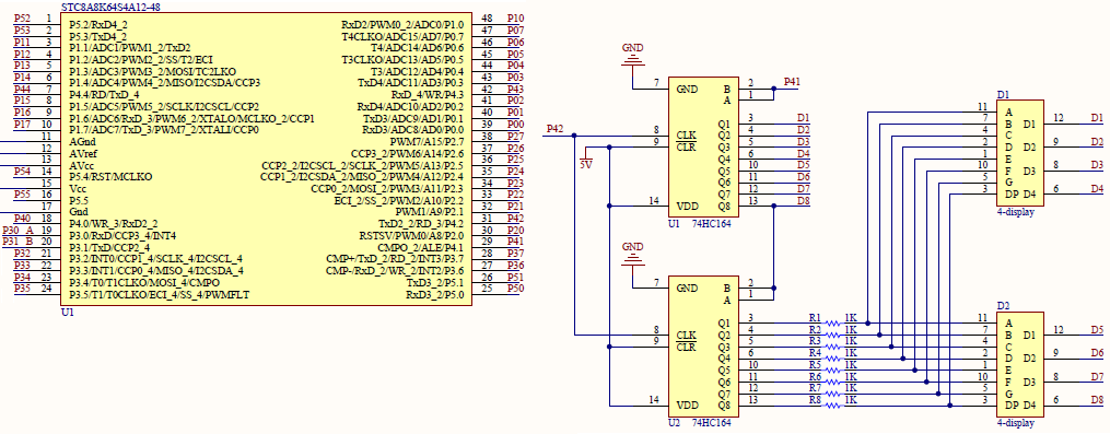
Schematic
Explanation
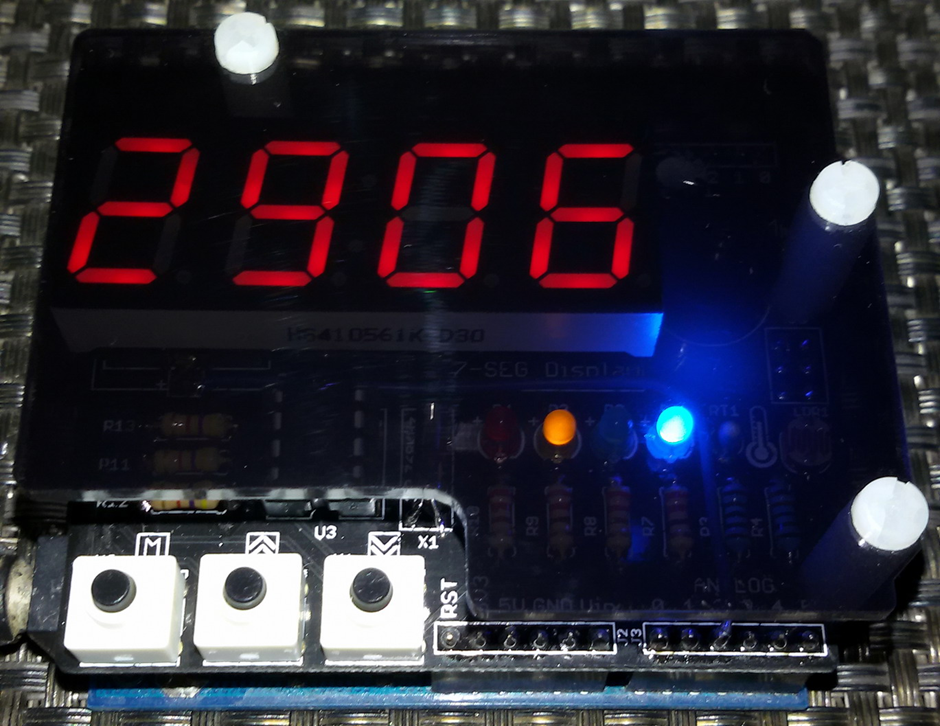
For demonstrating timer interrupt and seven segment displays, I used a simple dual 4-digit seven segment displays. It is made with a set of 74HC164 Serial-In-Parallel-Out (SPIO) shift register. In order to use it in real-time, its displays need to be scanned and updated at a fast rate without affecting other tasks.
This demo is a very important one as here multiple interrupts are employed and literally there is nothing inside the main loop. Things are done in such a way as if everything is parallelly done and in real-time. Firstly, the system clock and GPIOs are set. The system clock is set to 12 MHz. P4.1 and P4.2 are GPIOs that are used for driving the display. These drive data and clock lines of the display respectively.
 CLK_set_sys_clk(IRC_24M, 2, MCLK_SYSCLK_no_output, MCLK_out_P54);

 P41_push_pull_mode;
 P42_push_pull_mode;
ADC setup is as simple as the past ADC example. The conversion rate is set to about 3 kHz and the ADC interrupt is enabled. Note no external ADC pin is used as the goal here is to read the internal reference voltage source, i.e., ADC Channel 15.
 ADC_enable;
 ADC_result_format_right_aligned;
 ADC_set_conversion_speed(ADC_conv_128_CLKs);
 _enable_ADC_interrupt;
ADC interrupt is triggered when a conversion is completed. Inside this interrupt all we have to do is to read the ADC and clear the AD conversion completion flag.
 void ADC_ISR(void)
 interrupt 5
 {
   value_1 = ((ADC_RES << 8) | ADC_RESL);
   value_2 = ((value_1 * 5000.0) / 4096.0);
   clear_ADC_flag;
 }
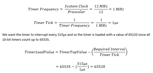
Timer 2 is used in this example and so let us now see how it is configured. There are eight seven segment displays and we would want them to be multiplexed quickly in order to make them appear to update simultaneously. We cannot afford to stay long for each display. Thus, this task should be completed within 2 – 3ms time. Due to this reason, the timer is set to interrupt every 315µs. The total time for all displays is therefore about 2.52ms (8 × 0.315ms).
 #define refresh_time_in_us              315
 #define max_tmr_cnt                     0xFFFF
 #define tmr_val                         (max_tmr_cnt - refresh_time_in_us)

 ....

 TMR2_setup(TMR2_sysclk, TMR2_clk_prescalar_12T);
 TMR2_load_counter_16(tmr_val);
 TMR2_start;
 _enable_TMR_2_interrupt;
Timer 2 is a 16-bit timer with auto-reload feature. In this demo, it is clocked internally with the 12 MHz system clock. This clock is further scaled down by a factor of 12 and so the timer’s ticks have a frequency of 1 MHz, i.e., the timer ticks are 1µs apart.
Lastly, the timer is started with its interrupt enabled.
Inside the timer interrupt the displays are updated by writing to the 74HC164 chips and clearing the timer overflow interrupt flag.
 void TMR_2_ISR(void)
 interrupt 12
 {
     switch(i)
     {
         case 0:
         {
             Write_74HC164(num[(value_1 / 1000)], pos[3]);
             break;
         }

         case 1:
         {
             Write_74HC164((num[((value_1 % 1000) / 100)]), pos[2]);
             break;
         }

         case 2:
         {
             Write_74HC164(num[((value_1 % 100) / 10)], pos[1]);
             break;
         }

         case 3:
         {
             Write_74HC164(num[(value_1 % 10)], pos[0]);
             break;
         }

         case 4:
         {
             Write_74HC164(num[(value_2 / 1000)] & 0xFE, pos[7]);
             break;
         }

         case 5:
         {
             Write_74HC164((num[((value_2 % 1000) / 100)]), pos[6]);
             break;
         }

         case 6:
         {
             Write_74HC164(num[((value_2 % 100) / 10)], pos[5]);
             break;
         }

         case 7:
         {
             Write_74HC164(num[(value_2 % 10)], pos[4]);
             break;
         }
     }

     i++;

     if(i >= 8)
     {
         i = 0;
     }

     clear_TMR_2_overflow_flag;
 }
The function below is the function for writing the 74HC164 shift-register ICs. Since the shift-registers are cascaded and we need them to work simultaneously, it is better to bit-bang seven segment data as 16-bit chunks – each word consisting of segment position and segment value data.
 void Write_74HC164(unsigned char val, unsigned char seg)
 {
     unsigned char s = 0x10;
     unsigned int temp = 0x0000;

     temp = (unsigned int)seg;
     temp <<= 8;
     temp |= (unsigned int)val;

     while(s > 0)
     {
         if((temp & 0x0001) != 0x0000)
         {
             DAT_pin_HIGH;
         }
         else
         {
             DAT_pin_LOW;
         }

         CLK_pin_HIGH;

         temp >>= 1;
         s--;

         CLK_pin_LOW;
     }
 }
Note interrupt priorities are not changed and are left in their default conditions.
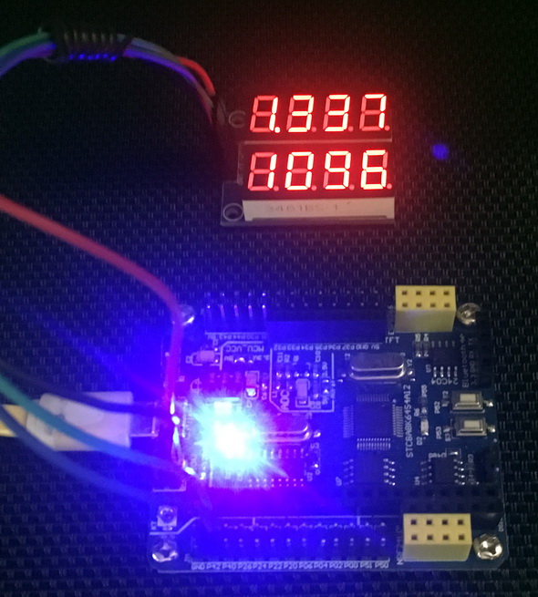
In the main, the channel to be read is selected and AD conversion is triggered. This operation is cycled every 400ms. Channel 15 is read here. Channel 15 is the internal reference voltage source. The internal reference voltage source has a typical value of 1.344V. The seven segment displays show ADC counts and voltage value.
 ADC_set_channel(CH15);
 delay_ms(10);
 ADC_start_conversion;
 delay_ms(400);
Demo
|
|
hello.
this is a very good effort to document all and still share with us. thank you very much.
I have one doubt . which programming tool are you using ?
Hi, I am trying to understand the STC15w408as chip, and found this site after weeks of searching for something that sets the output of the GPIO pins to a different state. I have a the 28 pin stc15w and have connected it up with a FTDI board and can write to it using PlatformIO. The thing is, the GPIO ports if just switched on or do a reset they are in the HIGH state and I am trying to make them LOW when you do a reset.
Is your BSP code doing this and for what port or GPIO pin is it setting? I could change your P52 and P55 in your SETUP to the GPIO pins on my development board but not under standing the BSP Code.
Wonder if you get this post? but any help would be gratefully received.
Hi,
How Purchase the development board. Please,give the purchase link for this Development board.
https://www.alibaba.com/product-detail/Development-board-1T-STC8A8K64S4A12-single-chip_62391507065.html
https://world.taobao.com/item/600882463994.htm
https://www.amazon.ca/STC8A8K64S4A12-Development-Controller-Module-Minimal/dp/B08D3Y3R6T
How To read and write string data using IAP into memory
void IAP_erase(unsigned int address)
{
IAP_CONTR = 0x80; //?? IAP
IAP_TPS = 12;
// IAP_CONTR = IAP_WT;
IAP_CMD = IAP_erase_command;
IAP_address(address);
IAP_trigger;
_nop_();
_nop_();
_nop_();
IAP_clear;
}
void IAP_send_string(unsigned int uc_send_addr,unsigned char *uca_send_string,unsigned int uc_number_of_bytes)
{
unsigned int buff_cntr=0;
do
{
IAP_CONTR = 0x80; //?? ISP/IAP ??
IAP_TPS = (unsigned char)(11509200 / 1000000L); //??????
IAP_CMD = IAP_write_command;
// IAP_CMD = IAP_write_command;
IAP_ADDRH = uc_send_addr / 256; //??????(??????????????)
IAP_ADDRL = uc_send_addr % 256; //??????
IAP_DATA = uca_send_string[buff_cntr]; //???? ISP_DATA,????????????
IAP_trigger;//IAP_TRIG();
_nop_();
_nop_();
_nop_();
uc_send_addr++;
// uca_send_string++;
buff_cntr++;
IAP_clear;
delay_ms(8);
}while(–uc_number_of_bytes);
}
void IAP_read_string(unsigned int uc_read_addr,unsigned char *data_read,unsigned int uc_number_of_bytes)
{
unsigned int buff_cntr=0;
do{
IAP_CONTR = 0x80; //?? ISP/IAP ??
IAP_TPS = (unsigned char)(11059200 / 1000000L); //??????
IAP_CMD = IAP_read_command;
// IAP_CMD = IAP_read_command;
IAP_ADDRH = uc_read_addr / 256; //??????(??????????????)
IAP_ADDRL = uc_read_addr % 256; //??????
IAP_trigger;//IAP_TRIG(); //?? 5AH,?? A5H ? ISP/IAP ?????,
//???????
//?? A5H ?, ISP/IAP ?????????
//CPU ?? IAP ???,?????????
_nop_();
_nop_();
_nop_();
data_read[buff_cntr] = IAP_DATA; //???????
uc_read_addr++;
// data_read++;
buff_cntr++;
IAP_clear;
delay_ms(8);
}while(–uc_number_of_bytes);
}
stores only last byte to all bytes of flash memory sector… memory sector selected is 0xF600
Hi, I am using STC MCU since 10 years. Tech support is ZERO. but they are low cost, very stable. Now I have a problem when the chip that I used is obsolete. Now start to use STC8C2K64S4-28I-LQFP32 but no stc8Cxx.h file, I am using stc8Hxx.h file which compiles but in some stage freeze, the existing firmware. With stc8hxx.h file I can compile STC8F2K64S4-28I-LQFP32 and works not bad
.
I wrote them many times for the stc8Cxx.h file never got answer. Where Can I find that file?
Thank you
Give me detail 8f2k64s281MCU read and write programmer
Give me detail 8f2k64s281reed and write programmer distal
Hi. Can you explain how to use I2C in the slave mode ?
I tried STC8G1K08A i2c in slave mode. Doesn’t work (no response). It does not enter interrupt, even on a start condition (everything according to the code in the documentation). I also tried master mode – it works.
Thanks for these tutorials. I’m getting back into STCmicro coding now, having left them alone for the past several years. Back then I only used the STC89C52RC (and C54RD) but this time I’m also using the more powerful STC15 and STC8 types. Your blogs provide a wealth of useful information.
Hello,
You have done great job with all these tutorials. I am an electronics engineer trying to learn some new stuff. I am located in Greece , Europe and I would like to purchase the development board that you are using and download some datasheets in English if possible but I cannot find them anywhere. Could you please help me?
I suggest you buy from AliExpress or similar platform that is available in your country…. You can find the English datasheet here. English documentation can be found in STC’s official websites such as this one….
Thank you very much for your help!!!
i always get excited when you release new tutorials ,you are really doing a great job i wish i could write code and develop libraries like you.
Well, this is very nice and thorough tutorial indeed, many thanks!
Unfortunately I doubt there is good any reason to learn the STC platform beyond curiosity.
The STC 8051, although pretty evolved from the original 8051 ISA, does not offer anything crucial to justify the relatively high price of these micros and development tools along with certain cumbersomeness of this ancient platform.
They simply can not compete even with the legacy Cortex M0 in any way. I am even not aware about any affordable debugger/emulator for them.
All in all, I would never recommend anybody to start learning/using any 8051 without some very good reason to do so.