Exploring STC 8051 Microcontrollers – Coding

|
|
My Customized BSP
To deal with the vast array of peripherals of STC8A8K64S4A12, I needed something to quickly deploy projects without going through the registers every time. Having gotten the idea of Board Support Package (BSP) while working with Nuvoton N76E003, it was time for me to develop something similar for STC micros here as officially STC does not have such beautiful software implementation for their microcontrollers. However, STC does provide lot of both C and assembly language examples in their reference manuals and programmer GUI unlike other manufacturers. Those examples, though helpful, do not fit in all possible scenarios and often incomplete in terms of meaning. By having a BSP, we can use our micro’s hardware peripherals more efficiently with ease and in a wide variety of ways. We would no longer need to create and call functions for hardware peripherals every time. Nuvoton, TI, STMicroelectronics, Silicon Labs and many other mainstream microcontroller manufacturers are tooling various methods to reduce coding efforts and aid in rapid code development.
It is not an easy task to go through an entire reference manual, reading and trying out everything one-by-one. However, I had to do it no matter how painstaking job it was. This is because firstly, I hate setting registers repetitively every single time when I want to make a new project and secondly, I want to make work easy so that less time, resource and effort are spent. I also have a tendency to forget things quickly. This solution will be as such that it can be modified easily and ported for other STC microcontrollers as well.
I have developed my BSP for STC8A8K64S4A12 in an orderly fashion. There are header files for each hardware peripherals that contain all necessary functions and definitions. An example of STC8A8K64S4A12’s watchdog timer’s header file is shown below:
/*
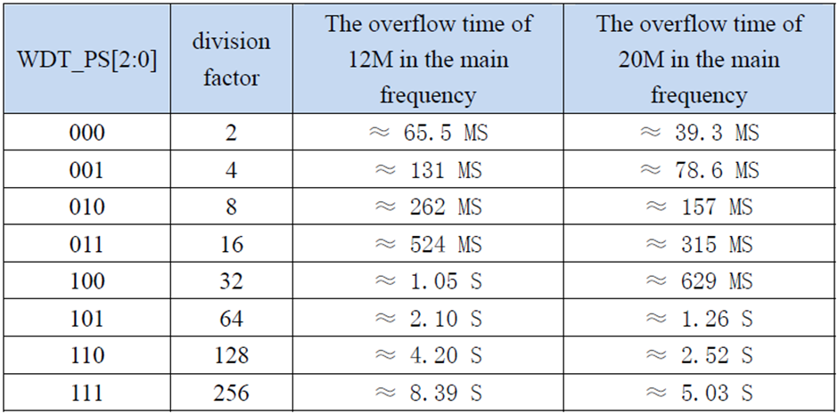
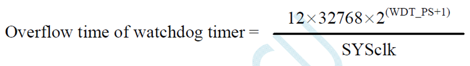
Watchdog Overflow Time = ((12 * 32768 * 2^(WDT_PS + 1)) / Sysclk)
*/
#define WDT_div_factor_2 0x00
#define WDT_div_factor_4 0x01
#define WDT_div_factor_8 0x02
#define WDT_div_factor_16 0x03
#define WDT_div_factor_32 0x04
#define WDT_div_factor_64 0x05
#define WDT_div_factor_128 0x06
#define WDT_div_factor_256 0x07
#define WDT_set_prescalar(value) do{ \
WDT_CONTR &= 0xF8; \
WDT_CONTR |= value; \
}while(0)
//CNT_mode
#define WDT_stop_counting_in_idle_mode 0x00
#define WDT_continue_counting_in_idle_mode 0x08
#define WDT_start bit_set(WDT_CONTR, 5)
#define WDT_get_overflow_flag get_bit(WDT_CONTR, 7)
#define WDT_clear_overflow_flag bit_set(WDT_CONTR, 7)
#define WDT_reset bit_set(WDT_CONTR, 4)
#define WDT_clear do{ \
WDT_CONTR = 0x00; \
}while(0)
#define WDT_setup(CNT_mode, PS) do{ \
WDT_clear; \
WDT_CONTR |= CNT_mode; \
WDT_set_prescalar(PS); \
}while(0)
Now let’s see what the registers and their settings look like:
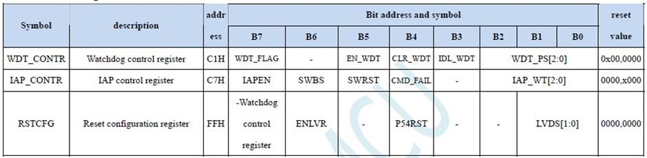
As we can see there are a whole bunch of settings that need attention while using. This is perhaps the easiest way to show what I wanted to achieve.
Please note that I have tested most of the stuffs that STC8A8K64S4A12 could offer. I tested them rigorously and with confidence I can say all of these functions have been found to be okay. Being the sole developer, I did my checks as much as possible but there could be unforeseen bugs that I may have overlooked. A typical case could be wrong function naming. This is so because during development of these BSP files I made several changes when new issues appeared. Therefore, I would like to request readers to report any issue when discovered and I would also like readers to read the reference manual of STC8 series completely if possible.
The examples presented in this document are based on my custom BSP and I believe that the journey with STC microcontroller supported by my BSP would be a joyful one.
|
|
hello.
this is a very good effort to document all and still share with us. thank you very much.
I have one doubt . which programming tool are you using ?
Hi, I am trying to understand the STC15w408as chip, and found this site after weeks of searching for something that sets the output of the GPIO pins to a different state. I have a the 28 pin stc15w and have connected it up with a FTDI board and can write to it using PlatformIO. The thing is, the GPIO ports if just switched on or do a reset they are in the HIGH state and I am trying to make them LOW when you do a reset.
Is your BSP code doing this and for what port or GPIO pin is it setting? I could change your P52 and P55 in your SETUP to the GPIO pins on my development board but not under standing the BSP Code.
Wonder if you get this post? but any help would be gratefully received.
Hi,
How Purchase the development board. Please,give the purchase link for this Development board.
https://www.alibaba.com/product-detail/Development-board-1T-STC8A8K64S4A12-single-chip_62391507065.html
https://world.taobao.com/item/600882463994.htm
https://www.amazon.ca/STC8A8K64S4A12-Development-Controller-Module-Minimal/dp/B08D3Y3R6T
How To read and write string data using IAP into memory
void IAP_erase(unsigned int address)
{
IAP_CONTR = 0x80; //?? IAP
IAP_TPS = 12;
// IAP_CONTR = IAP_WT;
IAP_CMD = IAP_erase_command;
IAP_address(address);
IAP_trigger;
_nop_();
_nop_();
_nop_();
IAP_clear;
}
void IAP_send_string(unsigned int uc_send_addr,unsigned char *uca_send_string,unsigned int uc_number_of_bytes)
{
unsigned int buff_cntr=0;
do
{
IAP_CONTR = 0x80; //?? ISP/IAP ??
IAP_TPS = (unsigned char)(11509200 / 1000000L); //??????
IAP_CMD = IAP_write_command;
// IAP_CMD = IAP_write_command;
IAP_ADDRH = uc_send_addr / 256; //??????(??????????????)
IAP_ADDRL = uc_send_addr % 256; //??????
IAP_DATA = uca_send_string[buff_cntr]; //???? ISP_DATA,????????????
IAP_trigger;//IAP_TRIG();
_nop_();
_nop_();
_nop_();
uc_send_addr++;
// uca_send_string++;
buff_cntr++;
IAP_clear;
delay_ms(8);
}while(–uc_number_of_bytes);
}
void IAP_read_string(unsigned int uc_read_addr,unsigned char *data_read,unsigned int uc_number_of_bytes)
{
unsigned int buff_cntr=0;
do{
IAP_CONTR = 0x80; //?? ISP/IAP ??
IAP_TPS = (unsigned char)(11059200 / 1000000L); //??????
IAP_CMD = IAP_read_command;
// IAP_CMD = IAP_read_command;
IAP_ADDRH = uc_read_addr / 256; //??????(??????????????)
IAP_ADDRL = uc_read_addr % 256; //??????
IAP_trigger;//IAP_TRIG(); //?? 5AH,?? A5H ? ISP/IAP ?????,
//???????
//?? A5H ?, ISP/IAP ?????????
//CPU ?? IAP ???,?????????
_nop_();
_nop_();
_nop_();
data_read[buff_cntr] = IAP_DATA; //???????
uc_read_addr++;
// data_read++;
buff_cntr++;
IAP_clear;
delay_ms(8);
}while(–uc_number_of_bytes);
}
stores only last byte to all bytes of flash memory sector… memory sector selected is 0xF600
Hi, I am using STC MCU since 10 years. Tech support is ZERO. but they are low cost, very stable. Now I have a problem when the chip that I used is obsolete. Now start to use STC8C2K64S4-28I-LQFP32 but no stc8Cxx.h file, I am using stc8Hxx.h file which compiles but in some stage freeze, the existing firmware. With stc8hxx.h file I can compile STC8F2K64S4-28I-LQFP32 and works not bad
.
I wrote them many times for the stc8Cxx.h file never got answer. Where Can I find that file?
Thank you
Give me detail 8f2k64s281MCU read and write programmer
Give me detail 8f2k64s281reed and write programmer distal
Hi. Can you explain how to use I2C in the slave mode ?
I tried STC8G1K08A i2c in slave mode. Doesn’t work (no response). It does not enter interrupt, even on a start condition (everything according to the code in the documentation). I also tried master mode – it works.
Thanks for these tutorials. I’m getting back into STCmicro coding now, having left them alone for the past several years. Back then I only used the STC89C52RC (and C54RD) but this time I’m also using the more powerful STC15 and STC8 types. Your blogs provide a wealth of useful information.
Hello,
You have done great job with all these tutorials. I am an electronics engineer trying to learn some new stuff. I am located in Greece , Europe and I would like to purchase the development board that you are using and download some datasheets in English if possible but I cannot find them anywhere. Could you please help me?
I suggest you buy from AliExpress or similar platform that is available in your country…. You can find the English datasheet here. English documentation can be found in STC’s official websites such as this one….
Thank you very much for your help!!!
i always get excited when you release new tutorials ,you are really doing a great job i wish i could write code and develop libraries like you.
Well, this is very nice and thorough tutorial indeed, many thanks!
Unfortunately I doubt there is good any reason to learn the STC platform beyond curiosity.
The STC 8051, although pretty evolved from the original 8051 ISA, does not offer anything crucial to justify the relatively high price of these micros and development tools along with certain cumbersomeness of this ancient platform.
They simply can not compete even with the legacy Cortex M0 in any way. I am even not aware about any affordable debugger/emulator for them.
All in all, I would never recommend anybody to start learning/using any 8051 without some very good reason to do so.