Exploring STC 8051 Microcontrollers – Coding

|
|
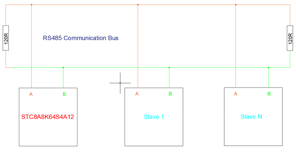
RS485 MODBUS
RS485 is basically a long-range reliable industrial version of serial communication. It is a hardware layer that can support anything from simple serial communication to complex software-based communication layers. MODBUS is such a software layer or protocol that can be used to reliably exchange data between devices. MODBUS (particularly MODBUS RTU) is very popular among industrial devices like energy meters, PLCs and sensor devices. MODBUS has some similarity with I2C in some regards.
Another similar communication medium is the Controller Area Network (CAN). CAN is not supported internally by STC microcontrollers unlike some advanced microcontrollers like the STM32s and other ARMs but with external hardware like MCP2551 and MCP2515 CAN communication can also be achieved. CAN communication is beyond the scope of this tutorial.
To know more about MODBUS, visit these links:
- https://en.wikipedia.org/wiki/Modbus
- https://modbus.org/docs/PI_MBUS_300.pdf
- https://modbus.org/docs/Modbus_Application_Protocol_V1_1b.pdf
Code
 #include "STC8xxx.h"
 #include "BSP.h"
 #include "LCD.c"
 #include "lcd_print.c"

 #define DIR_RX                                  P12_low
 #define DIR_TX                                  P12_high


 #define TX_buffer_length                        8
 #define RX_buffer_length                        10

 unsigned char cnt = 0x00;
 unsigned char RX_buffer[RX_buffer_length];

 static const unsigned char TX_buffer[TX_buffer_length] = {0x01, 0x03, 0x00, 0x00, 0x00, 0x02, 0xC4, 0x0B};

 void setup(void);
 void flush_RX_buffer(void);
 void send_read_command(void);
 unsigned int make_word(unsigned char HB, unsigned char LB);
 void get_HB_LB(unsigned int value, unsigned char *HB, unsigned char *LB);
 unsigned int MODBUS_RTU_CRC16(unsigned char *data_input, unsigned char data_length);

 void UART_2_ISR(void)
 interrupt 8
 {
   if(check_UART_2_RX_flag)
   {
     RX_buffer[cnt++] = UART2_read_buffer();
   }
 }

 void main(void)
 {
   unsigned int value = 0x0000;
   unsigned int CRC_check_1 = 0x0000;
   unsigned int CRC_check_2 = 0x0000;

   setup();

   LCD_goto(0, 0);
   LCD_putstr("R.H / %:");
   LCD_goto(0, 1);
   LCD_putstr("Temp/ C:");
   print_symbol(5, 1, 0);

   while(1)
   {
       send_read_command();

       CRC_check_1 = MODBUS_RTU_CRC16(RX_buffer, 7);
       CRC_check_2 = make_word(RX_buffer[8], RX_buffer[7]);

       if(CRC_check_1 == CRC_check_2)
       {
          value = make_word(RX_buffer[5], RX_buffer[6]);
          print_F(11, 0, (value / 10.0), 1);

          value = make_word(RX_buffer[3], RX_buffer[4]);
          print_F(11, 1, (value / 10.0), 1);
       }

       else
       {
         LCD_goto(12, 0);
         LCD_putstr("--.-");
         LCD_goto(12, 1);
         LCD_putstr("--.-");
       }

       P55_toggle;
       delay_ms(1000);
   };
 }

 void setup(void)
 {
   CLK_set_sys_clk(IRC_24M, 2, MCLK_SYSCLK_no_output, MCLK_out_P54);

   P12_push_pull_mode;
   P55_open_drain_mode;

   LCD_init();
   LCD_clear_home();
   load_custom_symbol();

   UART2_pin_option(0x00);

   UART2_init(9600, \
              UART2_timer_1T, \
              12000000);

   _enable_UART_2_interrupt;
   _enable_global_interrupt;
 }

 void flush_RX_buffer(void)
 {
   signed char i = (RX_buffer_length - 1);

   while(i > -1)
   {
     RX_buffer[i] = 0x00;
     i--;
   };
 }

 void send_read_command(void)
 {
   unsigned char i = 0x00;

   flush_RX_buffer();

   DIR_TX;

   for(i = 0; i < TX_buffer_length; i++)
   {
     UART2_write_buffer(TX_buffer[i]);
   }

   cnt = 0;
   DIR_RX;

   delay_ms(600);
 }

 unsigned int make_word(unsigned char HB, unsigned char LB)
 {
   unsigned int tmp = 0;

   tmp = HB;
   tmp <<= 8;
   tmp |= LB;

   return tmp;
 }

 void get_HB_LB(unsigned int value, unsigned char *HB, unsigned char *LB)
 {
   *LB = (value & 0x00FF);
   *HB = ((value & 0xFF00) >> 8);
 }

 unsigned int MODBUS_RTU_CRC16(unsigned char *data_input, unsigned char data_length)
 {
   static const unsigned int CRC_table[256] =
   {
      0x0000, 0xC0C1, 0xC181, 0x0140, 0xC301, 0x03C0, 0x0280, 0xC241,
      0xC601, 0x06C0, 0x0780, 0xC741, 0x0500, 0xC5C1, 0xC481, 0x0440,
      0xCC01, 0x0CC0, 0x0D80, 0xCD41, 0x0F00, 0xCFC1, 0xCE81, 0x0E40,
      0x0A00, 0xCAC1, 0xCB81, 0x0B40, 0xC901, 0x09C0, 0x0880, 0xC841,
      0xD801, 0x18C0, 0x1980, 0xD941, 0x1B00, 0xDBC1, 0xDA81, 0x1A40,
      0x1E00, 0xDEC1, 0xDF81, 0x1F40, 0xDD01, 0x1DC0, 0x1C80, 0xDC41,
      0x1400, 0xD4C1, 0xD581, 0x1540, 0xD701, 0x17C0, 0x1680, 0xD641,
      0xD201, 0x12C0, 0x1380, 0xD341, 0x1100, 0xD1C1, 0xD081, 0x1040,
      0xF001, 0x30C0, 0x3180, 0xF141, 0x3300, 0xF3C1, 0xF281, 0x3240,
      0x3600, 0xF6C1, 0xF781, 0x3740, 0xF501, 0x35C0, 0x3480, 0xF441,
      0x3C00, 0xFCC1, 0xFD81, 0x3D40, 0xFF01, 0x3FC0, 0x3E80, 0xFE41,
      0xFA01, 0x3AC0, 0x3B80, 0xFB41, 0x3900, 0xF9C1, 0xF881, 0x3840,
      0x2800, 0xE8C1, 0xE981, 0x2940, 0xEB01, 0x2BC0, 0x2A80, 0xEA41,
      0xEE01, 0x2EC0, 0x2F80, 0xEF41, 0x2D00, 0xEDC1, 0xEC81, 0x2C40,
      0xE401, 0x24C0, 0x2580, 0xE541, 0x2700, 0xE7C1, 0xE681, 0x2640,
      0x2200, 0xE2C1, 0xE381, 0x2340, 0xE101, 0x21C0, 0x2080, 0xE041,
      0xA001, 0x60C0, 0x6180, 0xA141, 0x6300, 0xA3C1, 0xA281, 0x6240,
      0x6600, 0xA6C1, 0xA781, 0x6740, 0xA501, 0x65C0, 0x6480, 0xA441,
      0x6C00, 0xACC1, 0xAD81, 0x6D40, 0xAF01, 0x6FC0, 0x6E80, 0xAE41,
      0xAA01, 0x6AC0, 0x6B80, 0xAB41, 0x6900, 0xA9C1, 0xA881, 0x6840,
      0x7800, 0xB8C1, 0xB981, 0x7940, 0xBB01, 0x7BC0, 0x7A80, 0xBA41,
      0xBE01, 0x7EC0, 0x7F80, 0xBF41, 0x7D00, 0xBDC1, 0xBC81, 0x7C40,
      0xB401, 0x74C0, 0x7580, 0xB541, 0x7700, 0xB7C1, 0xB681, 0x7640,
      0x7200, 0xB2C1, 0xB381, 0x7340, 0xB101, 0x71C0, 0x7080, 0xB041,
      0x5000, 0x90C1, 0x9181, 0x5140, 0x9301, 0x53C0, 0x5280, 0x9241,
      0x9601, 0x56C0, 0x5780, 0x9741, 0x5500, 0x95C1, 0x9481, 0x5440,
      0x9C01, 0x5CC0, 0x5D80, 0x9D41, 0x5F00, 0x9FC1, 0x9E81, 0x5E40,
      0x5A00, 0x9AC1, 0x9B81, 0x5B40, 0x9901, 0x59C0, 0x5880, 0x9841,
      0x8801, 0x48C0, 0x4980, 0x8941, 0x4B00, 0x8BC1, 0x8A81, 0x4A40,
      0x4E00, 0x8EC1, 0x8F81, 0x4F40, 0x8D01, 0x4DC0, 0x4C80, 0x8C41,
      0x4400, 0x84C1, 0x8581, 0x4540, 0x8701, 0x47C0, 0x4680, 0x8641,
      0x8201, 0x42C0, 0x4380, 0x8341, 0x4100, 0x81C1, 0x8081, 0x4040
    };

   unsigned char temp = 0;
   unsigned int CRC_word = 0xFFFF;

   while(data_length--)
   {
       temp = *data_input++ ^ CRC_word;
       CRC_word >>= 8;
       CRC_word ^= CRC_table[temp];
   }

   return CRC_word;
 }
Schematic
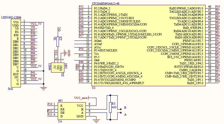
Explanation
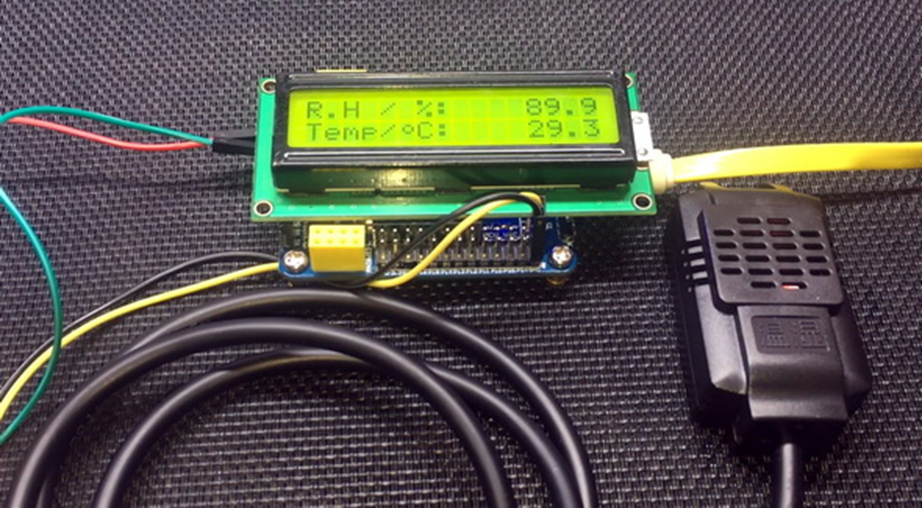
In this example, a MODBUS-based SHT20 relative humidity and temperature sensor is read with a STC micro. The sensor accepts MODBUS RTU data frames.
The setup is similar to the one we have already seen in the UART example and it should easy by now. The only exceptions are the UART module and the use of its interrupt.
 CLK_set_sys_clk(IRC_24M, 2, MCLK_SYSCLK_no_output, MCLK_out_P54);

 P12_push_pull_mode;
 P55_open_drain_mode;

 UART2_pin_option(0x00);

 UART2_init(9600, \
            UART2_timer_1T, \
            12000000);

 _enable_UART_2_interrupt;
 _enable_global_interrupt;
The UART’s interrupt is used for receiving data only.
 void UART_2_ISR(void)
 interrupt 8
 {
   if(check_UART_2_RX_flag)
   {
     RX_buffer[cnt++] = UART2_read_buffer();
   }
 }
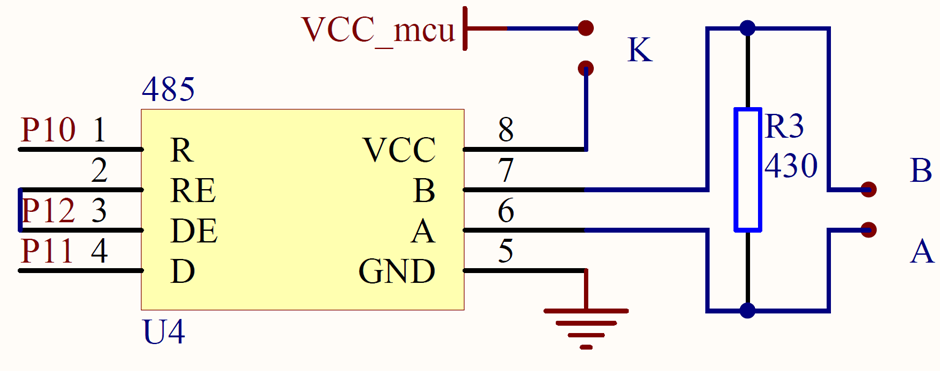
For sending data, the following function is used. In this function, previously received data are cleared first in order to make the micro ready to receive new batch of data and to make sure that past data do not make any conflict with the new ones. The onboard MAX485’s data direction is set to transmission mode and the transmission (TX) buffer data are sent via UART. MAX485’s mode operation is reset back to reception mode in order to receive new data.
static const unsigned char TX_buffer[TX_buffer_length] = {0x01, 0x03, 0x00, 0x00, 0x00, 0x02, 0xC4, 0x0B};

 ....

 void send_read_command(void)
 {
   unsigned char i = 0x00;

   flush_RX_buffer();

   DIR_TX;

   for(i = 0; i < TX_buffer_length; i++)
   {
     UART2_write_buffer(TX_buffer[i]);
   }

   cnt = 0;
   DIR_RX;

   delay_ms(600);
 }
The TX buffer contains the following information in the following order. This is the standard frame that should be sent by a host device to read holding registers. MODBUS RTU strictly prohibits other data frame formats and doing so will only lead to errors.
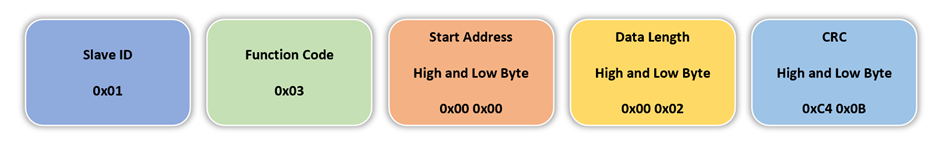
When the sensor receives these bytes in this order, it responds back with a reception or RX frame which is something like the frame shown below. This frame is similar to the TX frame but the important stuffs are the relative humidity and temperature data. These are the stuff that we mainly need. The values in frame shown below is just for giving an example.
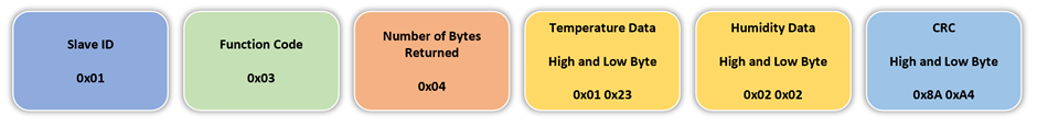
As per MODBUS RTU frame shown above, the slave ID is 0x01, the function code is 0x03 and 4 data bytes have been sent by the sensor along with the CRC fields. Function code 0x03 stands for reading holding registers. The temperature and the relative humidity are computed according to the calculation shown below:
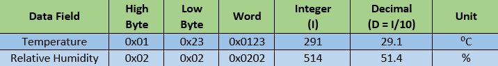
The table above shows that the high and low bytes are combined to make word and the word is divided by 10 to get desired outputs.
For more information on MODBUS, please refer to the docs mentioned in the beginning of this section. MODBUS RTU, itself, is a big topic and it is not possible to fully cover it in this tutorial. The code runs by querying the SHT20 sensor. After receiving all data from sensor, two Cyclic Redundancy Checks (CRC) are performed in order to ensure that valid and error-free data have been received. One CRC is the embedded with the RX frame and other is calculated using a CRC lookup table. Details of CRC lookup table and formula are covered in MODBUS RTU documentations. If CRCs match then the RX frame is considered to contain valid data and with the RX data, we can compute relative humidity and temperature values.
 send_read_command();

 CRC_check_1 = MODBUS_RTU_CRC16(RX_buffer, 7);
 CRC_check_2 = make_word(RX_buffer[8], RX_buffer[7]);

 if(CRC_check_1 == CRC_check_2)
 {
      value = make_word(RX_buffer[5], RX_buffer[6]);
      print_F(11, 0, (value / 10.0), 1);

      value = make_word(RX_buffer[3], RX_buffer[4]);
      print_F(11, 1, (value / 10.0), 1);
 }

 else
 {
      LCD_goto(12, 0);
      LCD_putstr("--.-");
      LCD_goto(12, 1);
      LCD_putstr("--.-");
 }

 P55_toggle;
 delay_ms(1000);
Demo
|
|
hello.
this is a very good effort to document all and still share with us. thank you very much.
I have one doubt . which programming tool are you using ?
Hi, I am trying to understand the STC15w408as chip, and found this site after weeks of searching for something that sets the output of the GPIO pins to a different state. I have a the 28 pin stc15w and have connected it up with a FTDI board and can write to it using PlatformIO. The thing is, the GPIO ports if just switched on or do a reset they are in the HIGH state and I am trying to make them LOW when you do a reset.
Is your BSP code doing this and for what port or GPIO pin is it setting? I could change your P52 and P55 in your SETUP to the GPIO pins on my development board but not under standing the BSP Code.
Wonder if you get this post? but any help would be gratefully received.
Hi,
How Purchase the development board. Please,give the purchase link for this Development board.
https://www.alibaba.com/product-detail/Development-board-1T-STC8A8K64S4A12-single-chip_62391507065.html
https://world.taobao.com/item/600882463994.htm
https://www.amazon.ca/STC8A8K64S4A12-Development-Controller-Module-Minimal/dp/B08D3Y3R6T
How To read and write string data using IAP into memory
void IAP_erase(unsigned int address)
{
IAP_CONTR = 0x80; //?? IAP
IAP_TPS = 12;
// IAP_CONTR = IAP_WT;
IAP_CMD = IAP_erase_command;
IAP_address(address);
IAP_trigger;
_nop_();
_nop_();
_nop_();
IAP_clear;
}
void IAP_send_string(unsigned int uc_send_addr,unsigned char *uca_send_string,unsigned int uc_number_of_bytes)
{
unsigned int buff_cntr=0;
do
{
IAP_CONTR = 0x80; //?? ISP/IAP ??
IAP_TPS = (unsigned char)(11509200 / 1000000L); //??????
IAP_CMD = IAP_write_command;
// IAP_CMD = IAP_write_command;
IAP_ADDRH = uc_send_addr / 256; //??????(??????????????)
IAP_ADDRL = uc_send_addr % 256; //??????
IAP_DATA = uca_send_string[buff_cntr]; //???? ISP_DATA,????????????
IAP_trigger;//IAP_TRIG();
_nop_();
_nop_();
_nop_();
uc_send_addr++;
// uca_send_string++;
buff_cntr++;
IAP_clear;
delay_ms(8);
}while(–uc_number_of_bytes);
}
void IAP_read_string(unsigned int uc_read_addr,unsigned char *data_read,unsigned int uc_number_of_bytes)
{
unsigned int buff_cntr=0;
do{
IAP_CONTR = 0x80; //?? ISP/IAP ??
IAP_TPS = (unsigned char)(11059200 / 1000000L); //??????
IAP_CMD = IAP_read_command;
// IAP_CMD = IAP_read_command;
IAP_ADDRH = uc_read_addr / 256; //??????(??????????????)
IAP_ADDRL = uc_read_addr % 256; //??????
IAP_trigger;//IAP_TRIG(); //?? 5AH,?? A5H ? ISP/IAP ?????,
//???????
//?? A5H ?, ISP/IAP ?????????
//CPU ?? IAP ???,?????????
_nop_();
_nop_();
_nop_();
data_read[buff_cntr] = IAP_DATA; //???????
uc_read_addr++;
// data_read++;
buff_cntr++;
IAP_clear;
delay_ms(8);
}while(–uc_number_of_bytes);
}
stores only last byte to all bytes of flash memory sector… memory sector selected is 0xF600
Hi, I am using STC MCU since 10 years. Tech support is ZERO. but they are low cost, very stable. Now I have a problem when the chip that I used is obsolete. Now start to use STC8C2K64S4-28I-LQFP32 but no stc8Cxx.h file, I am using stc8Hxx.h file which compiles but in some stage freeze, the existing firmware. With stc8hxx.h file I can compile STC8F2K64S4-28I-LQFP32 and works not bad
.
I wrote them many times for the stc8Cxx.h file never got answer. Where Can I find that file?
Thank you
Give me detail 8f2k64s281MCU read and write programmer
Give me detail 8f2k64s281reed and write programmer distal
Hi. Can you explain how to use I2C in the slave mode ?
I tried STC8G1K08A i2c in slave mode. Doesn’t work (no response). It does not enter interrupt, even on a start condition (everything according to the code in the documentation). I also tried master mode – it works.
Thanks for these tutorials. I’m getting back into STCmicro coding now, having left them alone for the past several years. Back then I only used the STC89C52RC (and C54RD) but this time I’m also using the more powerful STC15 and STC8 types. Your blogs provide a wealth of useful information.
Hello,
You have done great job with all these tutorials. I am an electronics engineer trying to learn some new stuff. I am located in Greece , Europe and I would like to purchase the development board that you are using and download some datasheets in English if possible but I cannot find them anywhere. Could you please help me?
I suggest you buy from AliExpress or similar platform that is available in your country…. You can find the English datasheet here. English documentation can be found in STC’s official websites such as this one….
Thank you very much for your help!!!
i always get excited when you release new tutorials ,you are really doing a great job i wish i could write code and develop libraries like you.
Well, this is very nice and thorough tutorial indeed, many thanks!
Unfortunately I doubt there is good any reason to learn the STC platform beyond curiosity.
The STC 8051, although pretty evolved from the original 8051 ISA, does not offer anything crucial to justify the relatively high price of these micros and development tools along with certain cumbersomeness of this ancient platform.
They simply can not compete even with the legacy Cortex M0 in any way. I am even not aware about any affordable debugger/emulator for them.
All in all, I would never recommend anybody to start learning/using any 8051 without some very good reason to do so.