Exploring STC 8051 Microcontrollers – Coding

|
|
Software I2C and Software UART
After trying to grasp the past software-based communication techniques, I think reader should now have some idea of the tricks employed to do the tasks. At this final stage, we are left with software I2C and software UART. The tricks behind software I2C are similar to our past encounters with one wire communications and TM1637. However, software UART implementation is a bit complicated.
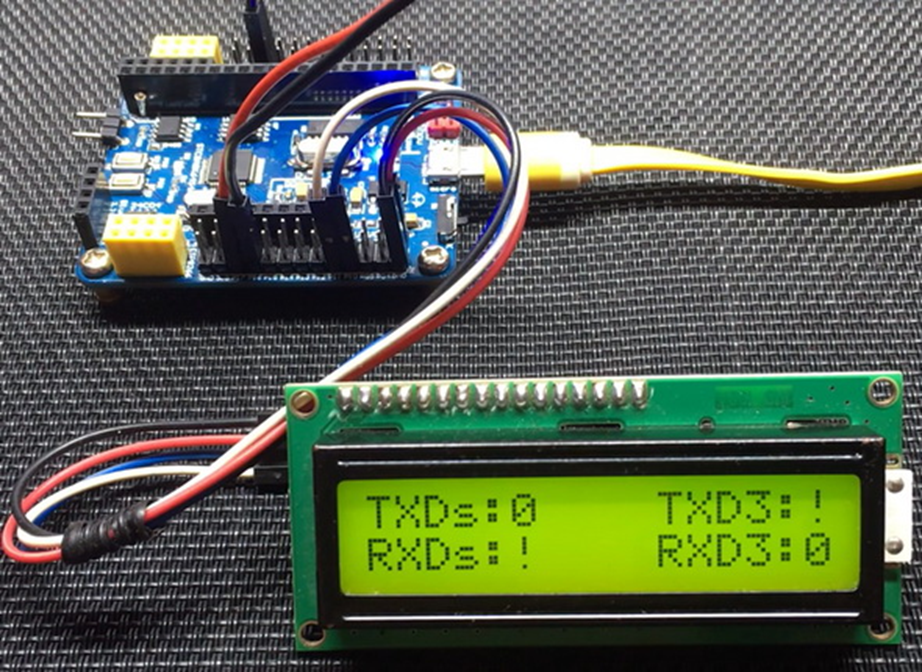
The demo for this example is a simple multi-UART chatting. One UART is hardware-based while the other is based on software. The chatting between the UARTs is displayed on I2C-based serial LCD. This LCD is driven using I2C-based PCF8574 GPIO expander.
Code
SW_I2C.h
 define SDA_DIR_OUT()   P10_push_pull_mode
 #define SDA_DIR_IN()    P10_input_mode

 #define SCL_DIR_OUT()   P11_push_pull_mode
 #define SCL_DIR_IN()    P11_input_mode

 #define SDA_HIGH()      P10_high
 #define SDA_LOW()       P10_low

 #define SCL_HIGH()      P11_high
 #define SCL_LOW()       P11_low

 #define SDA_IN()        P10_get_input

 #define I2C_ACK         0xFF
 #define I2C_NACK        0x00

 #define I2C_timeout     1000

 void SW_I2C_init(void);
 void SW_I2C_start(void);
 void SW_I2C_stop(void);
 unsigned char SW_I2C_read(unsigned char ack);
 void SW_I2C_write(unsigned char value);
 void SW_I2C_ACK_NACK(unsigned char mode);
 unsigned char SW_I2C_wait_ACK(void);
SW_I2C.c
 #include "SW_I2C.h"

 void SW_I2C_init(void)
 {
     SDA_DIR_OUT();
     SCL_DIR_OUT();
     delay_ms(10);
     SDA_HIGH();
     SCL_HIGH();
 }

 void SW_I2C_start(void)
 {
     SDA_DIR_OUT();
     SDA_HIGH();
     SCL_HIGH();
     delay_us(40);
     SDA_LOW();
     delay_us(40);
     SCL_LOW();
 }

 void SW_I2C_stop(void)
 {
     SDA_DIR_OUT();
     SDA_LOW();
     SCL_LOW();
     delay_us(40);
     SDA_HIGH();
     SCL_HIGH();
     delay_us(40);
 }

 unsigned char SW_I2C_read(unsigned char ack)
 {
     unsigned char i = 8;
     unsigned char j = 0;

     SDA_DIR_IN();

     while(i > 0)
     {
         SCL_LOW();
         delay_us(20);
         SCL_HIGH();
         delay_us(20);
         j <<= 1;

         if(SDA_IN() != 0x00)
         {
             j++;
         }

         delay_us(10);
         i--;
     };

     switch(ack)
     {
         case I2C_ACK:
         {
             SW_I2C_ACK_NACK(I2C_ACK);;
             break;
         }
         default:
         {
             SW_I2C_ACK_NACK(I2C_NACK);;
             break;
         }
     }

     return j;
 }

 void SW_I2C_write(unsigned char value)
 {
     unsigned char i = 8;

     SDA_DIR_OUT();
     SCL_LOW();

     while(i > 0)
     {

         if(((value & 0x80) >> 7) != 0x00)
         {
             SDA_HIGH();
         }
         else
         {
             SDA_LOW();
         }

         value <<= 1;
         delay_us(20);
         SCL_HIGH();
         delay_us(20);
         SCL_LOW();
         delay_us(20);
         i--;
     };
 }

 void SW_I2C_ACK_NACK(unsigned char mode)
 {
     SCL_LOW();
     SDA_DIR_OUT();

     switch(mode)
     {
         case I2C_ACK:
         {
             SDA_LOW();
             break;
         }
         default:
         {
             SDA_HIGH();
             break;
         }
     }

     delay_us(20);
     SCL_HIGH();
     delay_us(20);
     SCL_LOW();
 }

 unsigned char SW_I2C_wait_ACK(void)
 {
     signed int timeout = 0;

     SDA_DIR_IN();

     SDA_HIGH();
     delay_us(10);
     SCL_HIGH();
     delay_us(10);

     while(SDA_IN() != 0x00)
     {
         timeout++;

         if(timeout > I2C_timeout)
         {
             SW_I2C_stop();
             return 1;
         }
     };

     SCL_LOW();
     return 0;
 }
PCF8574.h
 #include "SW_I2C.c"

 #define PCF8574_address                 0x4E

 #define PCF8574_write_cmd               PCF8574_address
 #define PCF8574_read_cmd                (PCF8574_address | 1)

 void PCF8574_init(void);
 unsigned char PCF8574_read(void);
 void PCF8574_write(unsigned char data_byte);
PCF8574.c
 #include "PCF8574.h"

 void PCF8574_init(void)
 {
     SW_I2C_init();
     delay_ms(10);
 }

 unsigned char PCF8574_read(void)
 {
     unsigned char port_byte = 0;

     SW_I2C_start();
     SW_I2C_write(PCF8574_read_cmd);
     port_byte = SW_I2C_read(I2C_NACK);
     SW_I2C_stop();

     return port_byte;
 }

 void PCF8574_write(unsigned char data_byte)
 {
     SW_I2C_start();
     SW_I2C_write(PCF8574_write_cmd);
     SW_I2C_ACK_NACK(I2C_ACK);
     SW_I2C_write(data_byte);
     SW_I2C_ACK_NACK(I2C_ACK);
     SW_I2C_stop();
 }
LCD_2_Wire.h
 #include "PCF8574.c"

 #define clear_display                                0x01
 #define goto_home                                    0x02

 #define cursor_direction_inc                         (0x04 | 0x02)
 #define cursor_direction_dec                         (0x04 | 0x00)
 #define display_shift                                (0x04 | 0x01)
 #define display_no_shift                             (0x04 | 0x00)

 #define display_on                                   (0x08 | 0x04)
 #define display_off                                  (0x08 | 0x02)
 #define cursor_on                                    (0x08 | 0x02)
 #define cursor_off                                   (0x08 | 0x00)
 #define blink_on                                     (0x08 | 0x01)
 #define blink_off                                    (0x08 | 0x00)

 #define _8_pin_interface                             (0x20 | 0x10)
 #define _4_pin_interface                             (0x20 | 0x00)
 #define _2_row_display                               (0x20 | 0x08)
 #define _1_row_display                               (0x20 | 0x00)
 #define _5x10_dots                                   (0x20 | 0x40)
 #define _5x7_dots                                    (0x20 | 0x00)

 #define BL_ON                                         1
 #define BL_OFF                                        0

 #define dly                                           2

 #define DAT                                           1
 #define CMD                                           0

 void LCD_init(void);
 void LCD_toggle_EN(void);
 void LCD_send(unsigned char value, unsigned char mode);
 void LCD_4bit_send(unsigned char lcd_data);
 void LCD_putstr(char *lcd_string);
 void LCD_putchar(char char_data);
 void LCD_clear_home(void);
 void LCD_goto(unsigned char x_pos, unsigned char y_pos);
LCD_2_Wire.c
 #include "LCD_2_Wire.h"

 static unsigned char bl_state;
 static unsigned char data_value;

 void LCD_init(void)
 {
   PCF8574_init();
   delay_ms(10);

   bl_state = BL_ON;
   data_value = 0x04;
   PCF8574_write(data_value);

   delay_ms(10);

   LCD_send(0x33, CMD);
   LCD_send(0x32, CMD);

   LCD_send((_4_pin_interface | _2_row_display | _5x7_dots), CMD);
   LCD_send((display_on | cursor_off | blink_off), CMD);
   LCD_send((clear_display), CMD);
   LCD_send((cursor_direction_inc | display_no_shift), CMD);
 }

 void LCD_toggle_EN(void)
 {
   data_value |= 0x04;
   PCF8574_write(data_value);
   delay_ms(1);
   data_value &= 0xF9;
   PCF8574_write(data_value);
   delay_ms(1);
 }


 void LCD_send(unsigned char value, unsigned char mode)
 {
   switch(mode)
   {
      case CMD:
      {
         data_value &= 0xF4;
         break;
      }
      case DAT:
      {
         data_value |= 0x01;
         break;
      }
   }

   switch(bl_state)
   {
      case BL_ON:
      {
         data_value |= 0x08;
         break;
      }
      case BL_OFF:
      {
         data_value &= 0xF7;
         break;
      }
   }

   PCF8574_write(data_value);
   LCD_4bit_send(value);
   delay_ms(1);
 }


 void LCD_4bit_send(unsigned char lcd_data)
 {
   unsigned char temp = 0x00;

   temp = (lcd_data & 0xF0);
   data_value &= 0x0F;
   data_value |= temp;
   PCF8574_write(data_value);
   LCD_toggle_EN();

   temp = (lcd_data & 0x0F);
   temp <<= 0x04;
   data_value &= 0x0F;
   data_value |= temp;
   PCF8574_write(data_value);
   LCD_toggle_EN();
 }

 void LCD_putstr(char *lcd_string)
 {
   do
   {
     LCD_putchar(*lcd_string++);
   }while(*lcd_string != '\0') ;
 }

 void LCD_putchar(char char_data)
 {
   if((char_data >= 0x20) && (char_data <= 0x7F))
   {
     LCD_send(char_data, DAT);
   }
 }

 void LCD_clear_home(void)
 {
   LCD_send(clear_display, CMD);
   LCD_send(goto_home, CMD);
 }

 void LCD_goto(unsigned char x_pos,unsigned char y_pos)
 {
   if(y_pos == 0)
   {
     LCD_send((0x80 | x_pos), CMD);
   }
   else
   {
     LCD_send((0x80 | 0x40 | x_pos), CMD);
   }
 }
soft_UART.h
 #define tmr_max_cnt     0xFFFF

 //sysclk
 #define sysclk              12000000

 //baud rate
 #define baud_rate           9600

 //T_value
 #define _1T                 0x01
 #define _12T                0x0C

 #define tmr_load_value      (tmr_max_cnt - (sysclk / 3 / baud_rate / _1T))

 sbit RXD_pin = P1^6;
 sbit TXD_pin = P1^7;

 unsigned char TXing = 0x00;
 unsigned char RXing = 0x00;
 unsigned char TX_Bit = 0x00;
 unsigned char RX_Bit = 0x00;
 unsigned char TX_CNT = 0x00;
 unsigned char RX_CNT = 0x00;
 unsigned char TX_Data = 0x00;
 unsigned char RX_Data = 0x00;
 unsigned char TX_done = 0x00;
 unsigned char RX_done = 0x00;
 unsigned char TX_Buffer = 0x00;
 unsigned char RX_Buffer = 0x00;

 void soft_UART_init(void);
soft_UART.c
 #include "soft_UART.h"

 void soft_UART_init(void)
 {
   TXing = FALSE;
   RXing = FALSE;
   TX_CNT = 0x00;
   RX_CNT = 0x00;
   TX_done = TRUE;
   RX_done = FALSE;

   TMR2_setup(TMR2_sysclk, \
              TMR2_clk_prescalar_1T);

   TMR2_load_counter_16(tmr_load_value);

   TMR2_start;

   _enable_TMR_2_interrupt;
   _enable_global_interrupt;
 }

 void TMR_2_ISR(void)
 interrupt 12
 {
     if(RXing == TRUE)
     {
         if(--RX_CNT == 0x00)
         {
             RX_CNT = 0x03;

             if(--RX_Bit == 0x00)
             {
                 RX_Buffer = RX_Data;
                 RXing = FALSE;
                 RX_done = TRUE;
             }

             else
             {
                 RX_Data >>= 0x01;

                 if(RXD_pin == HIGH)
                 {
                     RX_Data |= 0x80;
                 }
             }
         }
     }

     else if(RXD_pin == FALSE)
     {
         RXing = TRUE;
         RX_CNT = 0x04;
         RX_Bit = 0x09;
     }

     if(--TX_CNT == 0x00)
     {
         TX_CNT = 0x03;

         if(TXing == TRUE)
         {
             if(TX_Bit == 0x00)
             {
                 TXD_pin = LOW;
                 TX_Data = TX_Buffer;
                 TX_Bit = 0x09;
             }

             else
             {
                 TX_Data >>= 0x01;

                 if(--TX_Bit == 0x00)
                 {
                     TXD_pin = HIGH;
                     TXing = FALSE;
                     TX_done = TRUE;
                 }

                 else
                 {
                     TXD_pin = CY;
                 }
             }

         }
     }
 }
main.c
 #include "STC8xxx.h"
 #include "BSP.h"
 #include "LCD_2_Wire.c"
 #include "soft_UART.c"

 void setup(void);

 void main(void)
 {
   unsigned char msg1[10] = {"0123456789"};
   unsigned char msg2[10] = {"!@#$%^&*()"};

   char i = 0x00;

   char rcv_s = 0x00;
   char rcv_3 = 0x00;

   setup();

   LCD_goto(0, 0);
   LCD_putstr("TXDs: ");
   LCD_goto(10, 0);
   LCD_putstr("TXD3: ");

   LCD_goto(0, 1);
   LCD_putstr("RXDs: ");
   LCD_goto(10, 1);
   LCD_putstr("RXD3: ");

   while(1)
   {
     for(i = 0; i < 10; i++)
     {
       if(TX_done == TRUE)
       {
           TX_done = FALSE;
           TX_Buffer = msg1[i];
           TXing = TRUE;
       }

       UART3_write_buffer(msg2[i]);

       LCD_goto(5, 0);
       LCD_putchar(msg1[i]);
       LCD_goto(15, 0);
       LCD_putchar(msg2[i]);

       if(RX_done == TRUE)
       {
         RX_done = FALSE;
         rcv_s = RX_Buffer;
       }

       rcv_3 = UART3_read_buffer();

       LCD_goto(5, 1);
       LCD_putchar(rcv_s);
       LCD_goto(15, 1);
       LCD_putchar(rcv_3);

       delay_ms(900);
     }
   };
 }

 void setup(void)
 {
   CLK_set_sys_clk(IRC_24M, 2, MCLK_SYSCLK_div_1, MCLK_out_P54);

   UART3_pin_option(0x00);

   UART3_init(9600, \
              UART3_baud_source_TMR3, \
              UART3_timer_1T, \
              12000000);

   LCD_init();
   LCD_clear_home();
   soft_UART_init();
 }
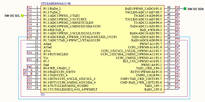
Schematic
Explanation
To use software UART efficiently, the following definitions have to defined properly. Unlike the past software communications that we have seen so far, software UART requires the use of a timer its overflow interrupt. Hardware UARTs also need timers for baud rate generation but here in software UART, a timer has a different but somewhat similar use. UART, itself, is asynchronous in nature and so its data timings must be as accurate as possible in order to reduce data loss, error and corruption. This fact becomes a more serious matter when it comes to software UART because not only we are dealing with an asynchronous communication but we will also be dealing it with software solution instead of actual hardware.
 //sysclk
 #define sysclk              12000000

 //baud rate
 #define baud_rate           9600

 //T_value
 #define _1T                 0x01
 #define _12T                0x0C

 #define tmr_load_value      (tmr_max_cnt - (sysclk / 3 / baud_rate / _1T))

 sbit RXD_pin = P1^6;
 sbit TXD_pin = P1^7;
Initialization of software UART is pretty easy. There are lot of variables that need to be initialized with some defaults and the timer to be used should be initialized and started along with the enabling of the interrupts.
 void soft_UART_init(void)
 {
   TXing = FALSE;
   RXing = FALSE;
   TX_CNT = 0x00;
   RX_CNT = 0x00;
   TX_done = TRUE;
   RX_done = FALSE;

   TMR2_setup(TMR2_sysclk, \
              TMR2_clk_prescalar_1T);

   TMR2_load_counter_16(tmr_load_value);

   TMR2_start;

   _enable_TMR_2_interrupt;
   _enable_global_interrupt;
 }
Inside the timer interrupt, data transmission and reception operations are done independently of the main loop. The whole operation is done in a similar process as one would expect with a real hardware UART. There are flags and buffers for both TX and RX operations and the timer’s interrupt is used to simulate baud rate as perfectly as possible.
 void TMR_2_ISR(void)
 interrupt 12
 {
     if(RXing == TRUE)
     {
         if(--RX_CNT == 0x00)
         {
             RX_CNT = 0x03;

             if(--RX_Bit == 0x00)
             {
                 RX_Buffer = RX_Data;
                 RXing = FALSE;
                 RX_done = TRUE;
             }

             else
             {
                 RX_Data >>= 0x01;

                 if(RXD_pin == HIGH)
                 {
                     RX_Data |= 0x80;
                 }
             }
         }
     }

     else if(RXD_pin == FALSE)
     {
         RXing = TRUE;
         RX_CNT = 0x04;
         RX_Bit = 0x09;
     }

     if(--TX_CNT == 0x00)
     {
         TX_CNT = 0x03;

         if(TXing == TRUE)
         {
             if(TX_Bit == 0x00)
             {
                 TXD_pin = LOW;
                 TX_Data = TX_Buffer;
                 TX_Bit = 0x09;
             }

             else
             {
                 TX_Data >>= 0x01;

                 if(--TX_Bit == 0x00)
                 {
                     TXD_pin = HIGH;
                     TXing = FALSE;
                     TX_done = TRUE;
                 }

                 else
                 {
                     TXD_pin = CY;
                 }
             }

         }
     }
 }
Demo
|
|
hello.
this is a very good effort to document all and still share with us. thank you very much.
I have one doubt . which programming tool are you using ?
Hi, I am trying to understand the STC15w408as chip, and found this site after weeks of searching for something that sets the output of the GPIO pins to a different state. I have a the 28 pin stc15w and have connected it up with a FTDI board and can write to it using PlatformIO. The thing is, the GPIO ports if just switched on or do a reset they are in the HIGH state and I am trying to make them LOW when you do a reset.
Is your BSP code doing this and for what port or GPIO pin is it setting? I could change your P52 and P55 in your SETUP to the GPIO pins on my development board but not under standing the BSP Code.
Wonder if you get this post? but any help would be gratefully received.
Hi,
How Purchase the development board. Please,give the purchase link for this Development board.
https://www.alibaba.com/product-detail/Development-board-1T-STC8A8K64S4A12-single-chip_62391507065.html
https://world.taobao.com/item/600882463994.htm
https://www.amazon.ca/STC8A8K64S4A12-Development-Controller-Module-Minimal/dp/B08D3Y3R6T
How To read and write string data using IAP into memory
void IAP_erase(unsigned int address)
{
IAP_CONTR = 0x80; //?? IAP
IAP_TPS = 12;
// IAP_CONTR = IAP_WT;
IAP_CMD = IAP_erase_command;
IAP_address(address);
IAP_trigger;
_nop_();
_nop_();
_nop_();
IAP_clear;
}
void IAP_send_string(unsigned int uc_send_addr,unsigned char *uca_send_string,unsigned int uc_number_of_bytes)
{
unsigned int buff_cntr=0;
do
{
IAP_CONTR = 0x80; //?? ISP/IAP ??
IAP_TPS = (unsigned char)(11509200 / 1000000L); //??????
IAP_CMD = IAP_write_command;
// IAP_CMD = IAP_write_command;
IAP_ADDRH = uc_send_addr / 256; //??????(??????????????)
IAP_ADDRL = uc_send_addr % 256; //??????
IAP_DATA = uca_send_string[buff_cntr]; //???? ISP_DATA,????????????
IAP_trigger;//IAP_TRIG();
_nop_();
_nop_();
_nop_();
uc_send_addr++;
// uca_send_string++;
buff_cntr++;
IAP_clear;
delay_ms(8);
}while(–uc_number_of_bytes);
}
void IAP_read_string(unsigned int uc_read_addr,unsigned char *data_read,unsigned int uc_number_of_bytes)
{
unsigned int buff_cntr=0;
do{
IAP_CONTR = 0x80; //?? ISP/IAP ??
IAP_TPS = (unsigned char)(11059200 / 1000000L); //??????
IAP_CMD = IAP_read_command;
// IAP_CMD = IAP_read_command;
IAP_ADDRH = uc_read_addr / 256; //??????(??????????????)
IAP_ADDRL = uc_read_addr % 256; //??????
IAP_trigger;//IAP_TRIG(); //?? 5AH,?? A5H ? ISP/IAP ?????,
//???????
//?? A5H ?, ISP/IAP ?????????
//CPU ?? IAP ???,?????????
_nop_();
_nop_();
_nop_();
data_read[buff_cntr] = IAP_DATA; //???????
uc_read_addr++;
// data_read++;
buff_cntr++;
IAP_clear;
delay_ms(8);
}while(–uc_number_of_bytes);
}
stores only last byte to all bytes of flash memory sector… memory sector selected is 0xF600
Hi, I am using STC MCU since 10 years. Tech support is ZERO. but they are low cost, very stable. Now I have a problem when the chip that I used is obsolete. Now start to use STC8C2K64S4-28I-LQFP32 but no stc8Cxx.h file, I am using stc8Hxx.h file which compiles but in some stage freeze, the existing firmware. With stc8hxx.h file I can compile STC8F2K64S4-28I-LQFP32 and works not bad
.
I wrote them many times for the stc8Cxx.h file never got answer. Where Can I find that file?
Thank you
Give me detail 8f2k64s281MCU read and write programmer
Give me detail 8f2k64s281reed and write programmer distal
Hi. Can you explain how to use I2C in the slave mode ?
I tried STC8G1K08A i2c in slave mode. Doesn’t work (no response). It does not enter interrupt, even on a start condition (everything according to the code in the documentation). I also tried master mode – it works.
Thanks for these tutorials. I’m getting back into STCmicro coding now, having left them alone for the past several years. Back then I only used the STC89C52RC (and C54RD) but this time I’m also using the more powerful STC15 and STC8 types. Your blogs provide a wealth of useful information.
Hello,
You have done great job with all these tutorials. I am an electronics engineer trying to learn some new stuff. I am located in Greece , Europe and I would like to purchase the development board that you are using and download some datasheets in English if possible but I cannot find them anywhere. Could you please help me?
I suggest you buy from AliExpress or similar platform that is available in your country…. You can find the English datasheet here. English documentation can be found in STC’s official websites such as this one….
Thank you very much for your help!!!
i always get excited when you release new tutorials ,you are really doing a great job i wish i could write code and develop libraries like you.
Well, this is very nice and thorough tutorial indeed, many thanks!
Unfortunately I doubt there is good any reason to learn the STC platform beyond curiosity.
The STC 8051, although pretty evolved from the original 8051 ISA, does not offer anything crucial to justify the relatively high price of these micros and development tools along with certain cumbersomeness of this ancient platform.
They simply can not compete even with the legacy Cortex M0 in any way. I am even not aware about any affordable debugger/emulator for them.
All in all, I would never recommend anybody to start learning/using any 8051 without some very good reason to do so.