Exploring STC 8051 Microcontrollers – Coding

|
|
External Interrupt (EXTI)
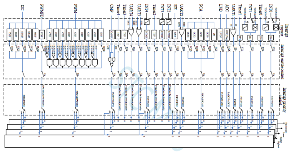
STC microcontrollers have complex interrupt systems. Literally, all internal peripherals have interrupt capabilities. The block diagram of STC8A8K64S4A12’s interrupt system shows this. In this section, we would see the use of external interrupt and in later examples we would see other interrupts.
External interrupt has lot of uses in modern embedded systems. When coupled with low power consumption modes, external interrupts can be used to wake up a device and do certain task upon user’s stimulated input via a button, keypad, touchpad, etc. External interrupts are what used in most portable battery-operated devices like computer mice, keyboards, remote controllers, etc. In such devices, precious battery energy is conserved by spending most time in low power modes and waiting for user interactions. When there is a user input, external interrupts are kicked in and some tasks are done quickly before returning to dormant low power modes.
Code
 #include "STC8xxx.h"
 #include "BSP.h"

 unsigned char s = 0;
 unsigned int i = 0;

 void setup(void);


 void EXT_0_ISR(void)
 interrupt 0
 {
     for(s = 0; s <= 9; s++)
     {
         P55_toggle;
         for(i = 0; i < 10000; i++);
     }
 }

 void EXT_1_ISR(void)
 interrupt 2
 {
     for(s = 0; s <= 9; s++)
     {
         P55_toggle;
         for(i = 0; i < 30000; i++);
     }
 }

 void main(void)
 {
     setup();

     while(1)
     {
         P55_low;
     };
 }

 void setup(void)
 {
     CLK_set_sys_clk(IRC_24M, 24, MCLK_SYSCLK_no_output, MCLK_out_P54);

     P55_open_drain_mode;

     EXT_0_priority_0;
     EXT_0_falling_edge_detection_only;
     _enable_EXT_0_interrupt;

     EXT_1_priority_1;
     EXT_1_falling_edge_detection_only;
     _enable_EXT_1_interrupt;

     _enable_global_interrupt;
 }
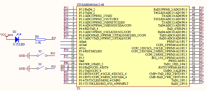
Schematic
Explanation
First, let us see how we can enable external interrupt. Although external interrupts are GPIO input feature, we do not have to set external interrupt pins as inputs. This is done automatically and internally.
8051 architecture allows prioritization of interrupts. This means that when there are simultaneous multiple interrupts, the interrupts are served in an orderly fashion according to the level of priority. STC8A8K64S4A12 has 22 interrupt sources and 4 levels of priority. Although it is not mandatory to set priority in most cases, some applications may need this feature. In this demo code, external interrupt 1 has higher priority than external interrupt 0 and so it would be processed first and then external interrupt 0 would be processed afterwards.
 EXT_0_priority_0;
 EXT_0_falling_edge_detection_only;
 _enable_EXT_0_interrupt;

 EXT_1_priority_1;
 EXT_1_falling_edge_detection_only;
 _enable_EXT_1_interrupt;

 _enable_global_interrupt;
The next thing to do when setting external interrupts is to let the MCU know which edges would trigger the interrupts. Finally, the interrupts are enabled along with global interrupt flag bit.
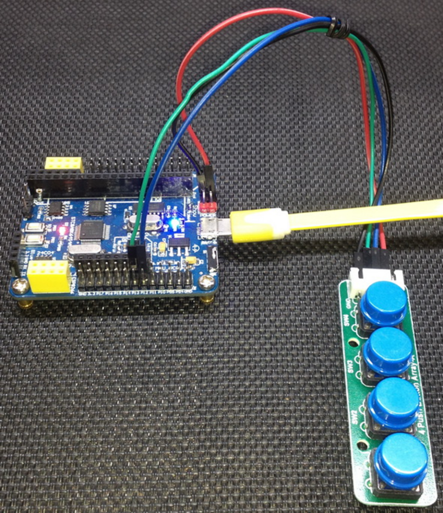
Like other examples onboard LED is used as an indicator. Inside each interrupt service routine, this LED is toggled but the rates of toggling are different. This would differentiate the interrupts.
 void EXT_0_ISR(void)
 interrupt 0
 {
     for(s = 0; s <= 9; s++)
     {
         P55_toggle;
         for(i = 0; i < 10000; i++);
     }
 }

 void EXT_1_ISR(void)
 interrupt 2
 {
     for(s = 0; s <= 9; s++)
     {
         P55_toggle;
         for(i = 0; i < 30000; i++);
     }
 }
When external interrupt 0 is triggered, the LED toggles fast and when external interrupt 1 is triggered, the LED toggles slowly. If external interrupt 0 is triggered while external interrupt 1 is being processed, external interrupt 0’s task is processed after completing external interrupt 1’s service routine. It is as if the MCU remembers the low priority interrupt after completing the higher priority interrupt. If external interrupt 1 is triggered while external interrupt 0 is being processed, the tasks in external interrupt 0 is temporarily suspended and external interrupt 1 is processed. After processing external interrupt 1, the suspended tasks of external interrupt 0 are resumed from where they were left.
Demo
|
|
hello.
this is a very good effort to document all and still share with us. thank you very much.
I have one doubt . which programming tool are you using ?
Hi, I am trying to understand the STC15w408as chip, and found this site after weeks of searching for something that sets the output of the GPIO pins to a different state. I have a the 28 pin stc15w and have connected it up with a FTDI board and can write to it using PlatformIO. The thing is, the GPIO ports if just switched on or do a reset they are in the HIGH state and I am trying to make them LOW when you do a reset.
Is your BSP code doing this and for what port or GPIO pin is it setting? I could change your P52 and P55 in your SETUP to the GPIO pins on my development board but not under standing the BSP Code.
Wonder if you get this post? but any help would be gratefully received.
Hi,
How Purchase the development board. Please,give the purchase link for this Development board.
https://www.alibaba.com/product-detail/Development-board-1T-STC8A8K64S4A12-single-chip_62391507065.html
https://world.taobao.com/item/600882463994.htm
https://www.amazon.ca/STC8A8K64S4A12-Development-Controller-Module-Minimal/dp/B08D3Y3R6T
How To read and write string data using IAP into memory
void IAP_erase(unsigned int address)
{
IAP_CONTR = 0x80; //?? IAP
IAP_TPS = 12;
// IAP_CONTR = IAP_WT;
IAP_CMD = IAP_erase_command;
IAP_address(address);
IAP_trigger;
_nop_();
_nop_();
_nop_();
IAP_clear;
}
void IAP_send_string(unsigned int uc_send_addr,unsigned char *uca_send_string,unsigned int uc_number_of_bytes)
{
unsigned int buff_cntr=0;
do
{
IAP_CONTR = 0x80; //?? ISP/IAP ??
IAP_TPS = (unsigned char)(11509200 / 1000000L); //??????
IAP_CMD = IAP_write_command;
// IAP_CMD = IAP_write_command;
IAP_ADDRH = uc_send_addr / 256; //??????(??????????????)
IAP_ADDRL = uc_send_addr % 256; //??????
IAP_DATA = uca_send_string[buff_cntr]; //???? ISP_DATA,????????????
IAP_trigger;//IAP_TRIG();
_nop_();
_nop_();
_nop_();
uc_send_addr++;
// uca_send_string++;
buff_cntr++;
IAP_clear;
delay_ms(8);
}while(–uc_number_of_bytes);
}
void IAP_read_string(unsigned int uc_read_addr,unsigned char *data_read,unsigned int uc_number_of_bytes)
{
unsigned int buff_cntr=0;
do{
IAP_CONTR = 0x80; //?? ISP/IAP ??
IAP_TPS = (unsigned char)(11059200 / 1000000L); //??????
IAP_CMD = IAP_read_command;
// IAP_CMD = IAP_read_command;
IAP_ADDRH = uc_read_addr / 256; //??????(??????????????)
IAP_ADDRL = uc_read_addr % 256; //??????
IAP_trigger;//IAP_TRIG(); //?? 5AH,?? A5H ? ISP/IAP ?????,
//???????
//?? A5H ?, ISP/IAP ?????????
//CPU ?? IAP ???,?????????
_nop_();
_nop_();
_nop_();
data_read[buff_cntr] = IAP_DATA; //???????
uc_read_addr++;
// data_read++;
buff_cntr++;
IAP_clear;
delay_ms(8);
}while(–uc_number_of_bytes);
}
stores only last byte to all bytes of flash memory sector… memory sector selected is 0xF600
Hi, I am using STC MCU since 10 years. Tech support is ZERO. but they are low cost, very stable. Now I have a problem when the chip that I used is obsolete. Now start to use STC8C2K64S4-28I-LQFP32 but no stc8Cxx.h file, I am using stc8Hxx.h file which compiles but in some stage freeze, the existing firmware. With stc8hxx.h file I can compile STC8F2K64S4-28I-LQFP32 and works not bad
.
I wrote them many times for the stc8Cxx.h file never got answer. Where Can I find that file?
Thank you
Give me detail 8f2k64s281MCU read and write programmer
Give me detail 8f2k64s281reed and write programmer distal
Hi. Can you explain how to use I2C in the slave mode ?
I tried STC8G1K08A i2c in slave mode. Doesn’t work (no response). It does not enter interrupt, even on a start condition (everything according to the code in the documentation). I also tried master mode – it works.
Thanks for these tutorials. I’m getting back into STCmicro coding now, having left them alone for the past several years. Back then I only used the STC89C52RC (and C54RD) but this time I’m also using the more powerful STC15 and STC8 types. Your blogs provide a wealth of useful information.
Hello,
You have done great job with all these tutorials. I am an electronics engineer trying to learn some new stuff. I am located in Greece , Europe and I would like to purchase the development board that you are using and download some datasheets in English if possible but I cannot find them anywhere. Could you please help me?
I suggest you buy from AliExpress or similar platform that is available in your country…. You can find the English datasheet here. English documentation can be found in STC’s official websites such as this one….
Thank you very much for your help!!!
i always get excited when you release new tutorials ,you are really doing a great job i wish i could write code and develop libraries like you.
Well, this is very nice and thorough tutorial indeed, many thanks!
Unfortunately I doubt there is good any reason to learn the STC platform beyond curiosity.
The STC 8051, although pretty evolved from the original 8051 ISA, does not offer anything crucial to justify the relatively high price of these micros and development tools along with certain cumbersomeness of this ancient platform.
They simply can not compete even with the legacy Cortex M0 in any way. I am even not aware about any affordable debugger/emulator for them.
All in all, I would never recommend anybody to start learning/using any 8051 without some very good reason to do so.