Tinkering TI MSP430F5529

|
|
Timer Interrupt – TA1
Timers become more useful when used with interrupts. At fixed intervals, interrupts occur and this process allows us to perform tasks that need periodic update. One common use of timer interrupt is to drive multiple seven segment displays. A timer is coded in such a way that its overflow interrupt triggers every millisecond. During this time, one seven segment display is updated. Since one millisecond interval is a very short duration for human vision to notice, we can update several seven segment displays in a matter of few milliseconds and our eyes will see that all displays have been simultaneously updated.
Code Example
#include "driverlib.h"
#include "delay.h"

#define GATE_HIGH                   GPIO_setOutputHighOnPin(GPIO_PORT_P8, GPIO_PIN2)
#define GATE_LOW                    GPIO_setOutputLowOnPin(GPIO_PORT_P8, GPIO_PIN2)

#define CLK_HIGH                    GPIO_setOutputHighOnPin(GPIO_PORT_P8, GPIO_PIN1)
#define CLK_LOW                     GPIO_setOutputLowOnPin(GPIO_PORT_P8, GPIO_PIN1)

#define A_HIGH                      GPIO_setOutputHighOnPin(GPIO_PORT_P2, GPIO_PIN6)
#define A_LOW                       GPIO_setOutputLowOnPin(GPIO_PORT_P2, GPIO_PIN6)

#define B_HIGH                      GPIO_setOutputHighOnPin(GPIO_PORT_P4, GPIO_PIN0)
#define B_LOW                       GPIO_setOutputLowOnPin(GPIO_PORT_P4, GPIO_PIN0)

#define C_HIGH                      GPIO_setOutputHighOnPin(GPIO_PORT_P2, GPIO_PIN3)
#define C_LOW                       GPIO_setOutputLowOnPin(GPIO_PORT_P2, GPIO_PIN3)

#define D_HIGH                      GPIO_setOutputHighOnPin(GPIO_PORT_P3, GPIO_PIN7)
#define D_LOW                       GPIO_setOutputLowOnPin(GPIO_PORT_P3, GPIO_PIN7)

#define SW                          GPIO_getInputPinValue(GPIO_PORT_P3, GPIO_PIN1)

#define top_seg                     4
#define bot_seg                     0

#define HIGH                        true
#define LOW                         false

const unsigned char num[0x0A] = {0xED, 0x21, 0x8F, 0xAB, 0x63, 0xEA, 0xEE, 0xA1, 0xEF, 0xEB};
unsigned char data_values[0x09] = {0x00, 0x00, 0x00, 0x00, 0x00, 0x00, 0x00, 0x00, 0x00};

unsigned char n = 0x00;
unsigned char SW_in = 0x00;

void clock_init(void);
void GPIO_init(void);
void timer_T1A1_init(void);
void write_74HC164(register unsigned char value);
void write_74HC145(register unsigned char channel);
void show_LEDs(unsigned char LED1_state, unsigned char LED2_state, unsigned char LED3_state, unsigned char LED4_state);
void show_numbers(signed int value, unsigned char pos);

#pragma vector = TIMER1_A1_VECTOR
__interrupt void Timer_A_ISR(void)
{
    Timer_A_clearTimerInterrupt(TIMER_A1_BASE);

    write_74HC164(data_values[n]);
    write_74HC145(n);

    n++;

    if(n > 9)
    {
      n = 0;
    }
}

void main(void)
{
    signed int i = 0;
    signed int j = 9999;

    WDT_A_hold(WDT_A_BASE);

    clock_init();
    GPIO_init();
    timer_T1A1_init();

    while(true)
    {
        switch(SW_in)
        {
             case 1:
             {
                 show_LEDs(1, 0, 0, 0);
                 break;
             }

             case 2:
             {
                 show_LEDs(0, 1, 0, 0);
                 break;
             }

             case 3:
             {
                 show_LEDs(0, 0, 1, 0);
                 break;
             }

             case 4:
             {
                 show_LEDs(0, 0, 0, 1);
                 break;
             }
        }

        SW_in = 0x00;

        i++;
        j--;

        if(i > 9999)
        {
            i = 0;
            j = 9999;
        }

        show_numbers(i, bot_seg);
        show_numbers(j, top_seg);

        delay_ms(100);
        show_LEDs(0, 0, 0, 0);
    };
}

void clock_init(void)
{
    PMM_setVCore(PMM_CORE_LEVEL_2);

    GPIO_setAsPeripheralModuleFunctionInputPin(GPIO_PORT_P5,
                                               (GPIO_PIN4 | GPIO_PIN2));

    GPIO_setAsPeripheralModuleFunctionOutputPin(GPIO_PORT_P5,
                                                (GPIO_PIN5 | GPIO_PIN3));

    UCS_setExternalClockSource(XT1_FREQ,
                               XT2_FREQ);

    UCS_turnOnXT2(UCS_XT2_DRIVE_4MHZ_8MHZ);

    UCS_turnOnLFXT1(UCS_XT1_DRIVE_0,
                    UCS_XCAP_3);

    UCS_initClockSignal(UCS_MCLK,
                        UCS_XT2CLK_SELECT,
                        UCS_CLOCK_DIVIDER_1);

    UCS_initClockSignal(UCS_SMCLK,
                        UCS_XT1CLK_SELECT,
                        UCS_CLOCK_DIVIDER_1);

    UCS_initClockSignal(UCS_ACLK,
                        UCS_XT2CLK_SELECT,
                        UCS_CLOCK_DIVIDER_1);
}

void GPIO_init(void)
{
    GPIO_setAsInputPin(GPIO_PORT_P3,
                       GPIO_PIN1);

    GPIO_setAsOutputPin(GPIO_PORT_P2,
                        GPIO_PIN3);
    GPIO_setDriveStrength(GPIO_PORT_P2,
                          GPIO_PIN3,
                          GPIO_FULL_OUTPUT_DRIVE_STRENGTH);

    GPIO_setAsOutputPin(GPIO_PORT_P2,
                        GPIO_PIN6);

    GPIO_setDriveStrength(GPIO_PORT_P2,
                          GPIO_PIN6,
                          GPIO_FULL_OUTPUT_DRIVE_STRENGTH);

    GPIO_setAsOutputPin(GPIO_PORT_P3,
                        GPIO_PIN7);

    GPIO_setDriveStrength(GPIO_PORT_P3,
                          GPIO_PIN7,
                          GPIO_FULL_OUTPUT_DRIVE_STRENGTH);

    GPIO_setAsOutputPin(GPIO_PORT_P4,
                        GPIO_PIN0);

    GPIO_setDriveStrength(GPIO_PORT_P4,
                          GPIO_PIN0,
                          GPIO_FULL_OUTPUT_DRIVE_STRENGTH);

    GPIO_setAsOutputPin(GPIO_PORT_P8,
                        GPIO_PIN1);

    GPIO_setDriveStrength(GPIO_PORT_P8,
                          GPIO_PIN1,
                          GPIO_FULL_OUTPUT_DRIVE_STRENGTH);

    GPIO_setAsOutputPin(GPIO_PORT_P8,
                        GPIO_PIN2);

    GPIO_setDriveStrength(GPIO_PORT_P8,
                          GPIO_PIN2,
                          GPIO_FULL_OUTPUT_DRIVE_STRENGTH);
}

void timer_T1A1_init(void)
{
    Timer_A_initUpModeParam UpModeParam = {0};

    UpModeParam.clockSource = TIMER_A_CLOCKSOURCE_ACLK;
    UpModeParam.clockSourceDivider = TIMER_A_CLOCKSOURCE_DIVIDER_1;
    UpModeParam.timerPeriod = 9999;
    UpModeParam.timerInterruptEnable_TAIE = TIMER_A_TAIE_INTERRUPT_ENABLE;
    UpModeParam.captureCompareInterruptEnable_CCR0_CCIE =
                                      TIMER_A_CCIE_CCR0_INTERRUPT_DISABLE;
    UpModeParam.timerClear = TIMER_A_DO_CLEAR;
    UpModeParam.startTimer = true;

    Timer_A_initUpMode(TIMER_A1_BASE,
                       &UpModeParam);

    Timer_A_startCounter(TIMER_A1_BASE,
                         TIMER_A_UP_MODE);

    __enable_interrupt();
}

void write_74HC164(register unsigned char value)
{
  register unsigned char s = 0x08;

  while(s > 0)
  {
        if((value & 0x80) != 0x00)
        {
            GATE_HIGH;
        }
        else
        {
            GATE_LOW;
        }

        CLK_HIGH;
        CLK_LOW;

        value <= 0) && (value  9) && (value  99) && (value  999) && (value <= 9999))
  {
    ch = (value % 10);
    data_values[(0 + pos)] = num[ch];
    ch = ((value / 10) % 10);
    data_values[(1 + pos)] = num[ch];
    ch = ((value / 100) % 10);
    data_values[(2 + pos)] = num[ch];
    ch = (value / 1000);
    data_values[(3 + pos)] = num[ch];
  }
}
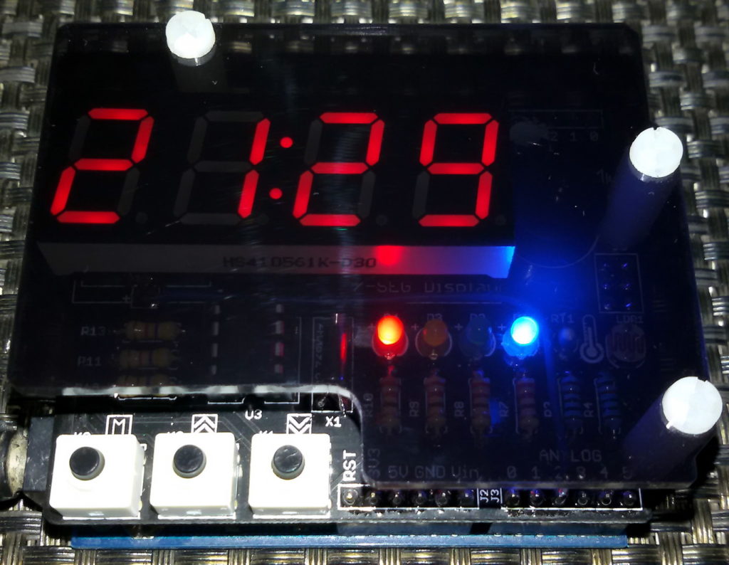
Hardware Setup
Explanation
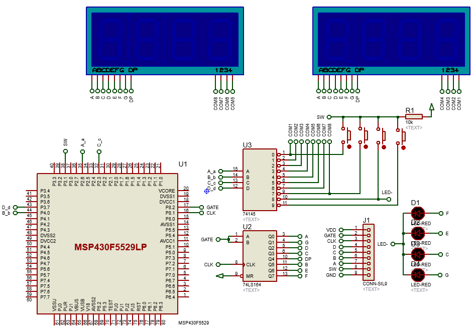
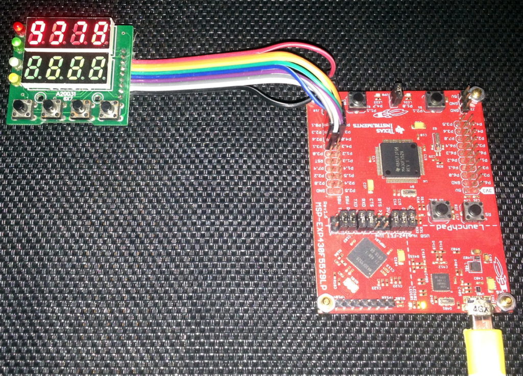
Timer interrupt is best understood by using it to scan multiple seven segment displays and buttons. This time timer TA1 is used.
void timer_T1A1_init(void)
{
    Timer_A_initUpModeParam UpModeParam = {0};

    UpModeParam.clockSource = TIMER_A_CLOCKSOURCE_ACLK;
    UpModeParam.clockSourceDivider = TIMER_A_CLOCKSOURCE_DIVIDER_1;
    UpModeParam.timerPeriod = 9999;
    UpModeParam.timerInterruptEnable_TAIE = TIMER_A_TAIE_INTERRUPT_ENABLE;
    UpModeParam.captureCompareInterruptEnable_CCR0_CCIE =
                                          TIMER_A_CCIE_CCR0_INTERRUPT_DISABLE;
    UpModeParam.timerClear = TIMER_A_DO_CLEAR;
    UpModeParam.startTimer = true;

    Timer_A_initUpMode(TIMER_A1_BASE, &UpModeParam);

    Timer_A_startCounter(TIMER_A1_BASE, TIMER_A_UP_MODE);

    __enable_interrupt();
}
Timer TA1 is clocked with ACLK which in turn is being feed with 4MHz XT2CLK source. No divider is used at any stage and so, the timer will tick every 0.25µs.
UCS_initClockSignal(UCS_ACLK, UCS_XT2CLK_SELECT, UCS_CLOCK_DIVIDER_1);
We wish to have a time period of 2.5 ms and thus, here we will be using the timer in up mode with a top value of 9999, i.e. 10000 counts. Up mode is similar to previously seen continuous mode. The only difference is the fact that in continuous mode the top value of a timer is fixed at 65535 count while in up mode, the top value can be set to anything between 0 to 65535. The timer will count from 0 to 9999, i.e. there are 10000 ticks before timer overflow. Since one tick is 0.25 µs, 10000 ticks equal 2.5 ms (0.25 µs x 10000 = 2.5 ms).
We will only need timer interrupt. We won’t be using any capture-compare interrupt and so we have to disable it. As with previous examples we have to clear any past setting although there is none.
After setting up the timer’s settings, we will just start it and enable global interrupt as to begin time count.
Now let’s see what’s being done inside the timer interrupt? According to the schematic and objective of this project, we need to update all seven segment displays and read the 4-bit keypad so quickly as if everything appears to work in real time and without any lag.
#pragma vector = TIMER1_A1_VECTOR
__interrupt void Timer_A_ISR(void)
{
    Timer_A_clearTimerInterrupt(TIMER_A1_BASE);

    write_74HC164(data_values[n]);
    write_74HC145(n);

    n++;

    if(n > 9)
    {
      n = 0;
    }
}
Inside timer interrupt subroutine, both logic ICs are updated. Firstly, the number to be displayed is sent to the 74HC164 IC and then the seven-segment display to show the number is updated by writing the 74HC145 IC. At every interrupt, one seven segment display is updated. There are 8 such displays and so it takes about 20 ms to update all of these displays. During this time the keypad is also scanned in the main loop. With different key presses, different LEDs light up.
switch(SW_in)
{
       case 1:
        {
            show_LEDs(1, 0, 0, 0);
            break;
        }
        case 2:
        {
             show_LEDs(0, 1, 0, 0);
             break;
        }
  case 3:
        {
             show_LEDs(0, 0, 1, 0);
             break;
        }
  case 4:
         {
             show_LEDs(0, 0, 0, 1);
             break;
         }
}

SW_in = 0x00;
Demo
|
|
Hello, dear sir Shawon Shahryiar, could you send me the GRACE program by email? I can’t find it anywhere on the Internet. Thank you very much and all the best.
https://www.dropbox.com/scl/fi/6jgmxuuwl9dw2zo9mpuwm/grace_setup_2.2.0.00006.rar?rlkey=gm20hy3odiuyajjow2pas3iz0&st=hhfakdjt&dl=0
Hello, what software are you using for the Hardware setup images and does it support simulation for the MSP430F5529
I used Proteus VSM for drawing schematics but it doesn’t support simulation.
Hi,
Im interfacing MSP430F5529 with MAX17055 fuel guage. while reading 16 bit value, the first byte im receiving is 0. so while reading multiple registers continuously the data exchange is happening, but im getting the correct data. Can anyone suggest me what will be the issue? why im getting 0 in first byte?
read16_bit data code:
uint16_t value = 0;
USCI_B_I2C_setslaveaddress(USCI_B1_BASE, slave_address);
USCI_B_I2C_setmode(USCI_B1_BASE, USCI_B_I2C_TRANSMIT_MODE);
USCI_B_I2C_masterSendStart(USCI_B1_BASE);
while (!USCI_B_I2C_masterSendStart(USCI_B1_BASE));
USCI_B_I2C_mastterSendSingleByte(USCI_B1_BASE, reg_address);
USCI_B_I2C_setslaveaddress(USCI_B1_BASE, slave_address);
USCI_B_I2C_setmode(USCI_B1_BASE, USCI_B_I2C_TRANSMIT_MODE);
USCI_B_I2C_masterReceiveMultiByteStart(USCI_B1_BASE);
uint8_t lb = USCI_B_I2C_masterReceiveMultiByteNext(USCI_B1_BASE);
uint8_t hb = USCI_B_I2C_masterReceiveMultiByteFinish(USCI_B1_BASE);
while (USCI_B_I2C_isBusBusy(USCI_B_BASE));
value = lb << 8;
value |= hb;
return value;
In code, after sending reg address, it will be recieve mode. its a type mistake
Hi, im trying to send the command from the terminal view. i can able to send the command and tried to blink p1.0 led in msp430f5529 controller, its working fine. And im using led driver IS31FL3236A interfaced with msp430f5529 controller, i can able to interface im getting the expected output.
now i need to send the command from seriak monitor based on that command i2c communication need to start. both communication are working fine, when it runs separately. its not working when i tried to combine.
any one had any idea, why it is happening or what will be the issue?
It could be due to:
1. conflicts in clock settings
2. hardware conflict like pin mapping
3. code is getting stuck or waiting for one communication line to finish
4. use of polling method instead of interrupt-driven coding
Hi, thank you for the respose.
Do I need to use different clock initialization for I2C and UART communication? if YES, can you explain how to do that?
I mean check which clock has been set for UART and I2C…. Is it SMCLK, MCLK, etc and is it tuned to right frequency required by the respective hardware?
Is there any example on how to implement polling method in uart?
Why go for polling method when it is a blocking method of coding? It is better to use interrupts instead at least for UART receive.
yes!! currently in my code, only for uart im using interrupts to recieve command from serial monitor. Im not using interrupt for I2C communication.
so the issue is must be in clock initialization. right?
For UART, im using USCI_A1_BASE. and for I2C, im using USCI_B1_BASE.
And another thing i need to ask is, in uart when i tried blink led(p1.0) in msp430f5529 by passing command. here, without clock I’m getting output. how it is possible?
And for both i2c and uart i gave SMCLK with 1Mhz
I am surprised and happy to find this tutorial on the F5529 as TI makes a lot of different devices.
Thank you very much for putting in the extra knowledge in each segment, made reading worthwhile.
Good Work!
lovely tutorial but to be honest I don’t think I’d be investing my time on this board to start with it’s not cheap and readily available as the stm32 boards can you please do more tutorials on stm32 board’s and the stc micros thanks
Hello, I try to program MSP430FR6047 but i get error “the debug interface to the device has been secured”. when flashing using uniflash and when program using CCS this happen. can you help me to solve this problem
You can try “On connect, erase user code and unlock the device” option.
Pingback: Tinkering TI MSP430F5529 – gStore
Hello
I am doing project of msp430g2553 interface(using i2c communication) with temp 100(temperature sensor) and try to read the temperature in dispaly(16*2) but didn’t get the out put (using code composer studio) can u share me any example code for this project
Thank you sir,
Which sensor? Did you use pullup resistors for SDA-SCL pins?
Where is lcd_print.h?
All files and docs are here:
https://libstock.mikroe.com/projects/view/3233/tinkering-ti-msp430f5529
You want the truth? TI makes and sell “underpowered micros”, you know? Low everything, not only the power but also peripherals. So the price is not justified.
Otherwise, if I’ll move there, I’ll introduce them to my small hobby projects – there are still some advantages.
I may even make a visual configuration tool of my own for them…
Yeah the prices of TI products are higher than other manufacturers but I don’t think the hardware peripherals are inferior.
Not inferior but in not enough numbers compared to STM32.
True