Tinkering TI MSP430F5529

|
|
USB Module Overview
The USB module of MSP430F5529 is not very difficult to use. TI has provided some working deploy-able examples in their 430ware software suite. However, some explanation is needed at first to get started. We will go through two basic USB module examples – USB CDC and USB HID.
In simple terms, USB CDC is a USB mode with which we can emulate virtual serial COM ports and USB HID is another common USB mode with which we can make devices like USB keyboard, mouse, input devices, printer, scanner, etc as well as other similar I/O devices. MSP430F5529 also supports mass storage class. In all cases, we create a way to make our MSP430 micro communicate with a host device.
Now let’s see what we need to get started with USB coding. Apart from driverlib files and personal libraries we will need additional libraries for USB software development. Note the following folders:
- USB API Folder
- USB_app Folder
- USB_config Folder
Apart from these we’ll need some important files too:
- Hal header and source files
- system_pre_init source file
Fortunately for us we don’t have to change anything in these files/folders. We just have to add them in our USB projects and the process of adding doesn’t need any special attention. Alternatively, we can simply copy example USB projects from MSP430ware and have them customized as per need.
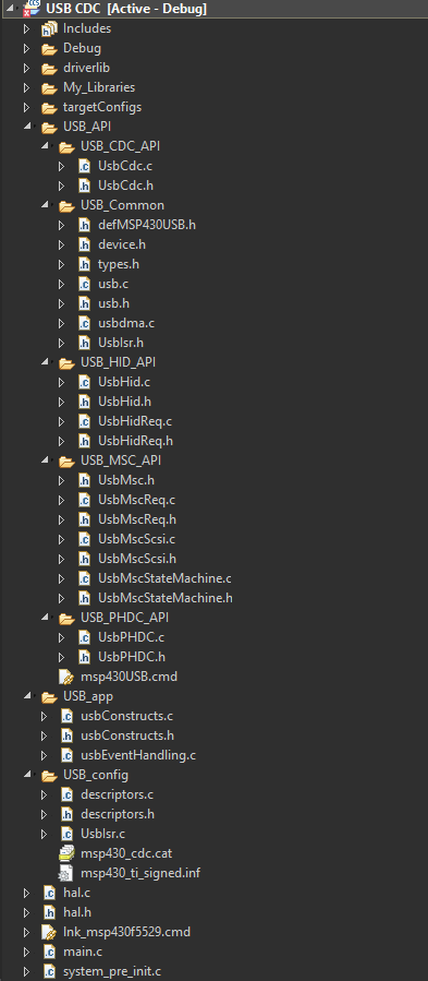
Very briefly speaking, USB API folder, sub-folders and files in them are what describe a specific USB mode’s working. They list relevant functions for a given mode. USB_app folder and associated files further elaborate these operations. USB devices need descriptors and USB_config folder and files contain them. Hal source and header files contain clock and GPIO setups and system_pre_init basically contains nothing except watchdog setup.
Shown below is the folder tree of a typical USB project. All I stated so far is what boils down to this folder tree.
In the main, all of the aforementioned files are included as shown below:
#include "driverlib.h"

#include "USB_config/descriptors.h"
#include "USB_API/USB_Common/device.h"
#include "USB_API/USB_Common/usb.h"
#include "USB_API/USB_CDC_API/UsbCdc.h"
#include "USB_app/usbConstructs.h"

#include "hal.h"
Pay attention to these functions shown below:
PMM_setVCore(PMM_CORE_LEVEL_2);
USBHAL_initPorts();
USBHAL_initClocks(8000000);
USB_setup(TRUE, TRUE);
Clock setting is very important because USB hardware is clock sensitive. FLL is used for both MCLK and USB clock. It is also necessary to set the right level for PMM core. Usually level 2 is preferred as the clock speed is 8MHz. On start-up, all GPIO ports are driven low to avoid floating input and unwanted EMI-related issues. This causes some additional power consumption. Thus, it is recommended to setup GPIOs for other tasks after initial USB port initialization. Please refer to TI’s official docs for additional info.
If you are not using official TI boards or equivalents and designing stuffs on your own then pay attention to USB hardware design considerations. EMC considerations are also needed to focused more alongside good PCB layout practices.
In addition to these, we can develop our own customized PC/mobile applications with Visual C Sharp (C#), Visual Basic or some other similar computer programming languages. This part is beyond the scope of this tutorial and won’t be discussed.
|
|
Hello, dear sir Shawon Shahryiar, could you send me the GRACE program by email? I can’t find it anywhere on the Internet. Thank you very much and all the best.
https://www.dropbox.com/scl/fi/6jgmxuuwl9dw2zo9mpuwm/grace_setup_2.2.0.00006.rar?rlkey=gm20hy3odiuyajjow2pas3iz0&st=hhfakdjt&dl=0
Hello, what software are you using for the Hardware setup images and does it support simulation for the MSP430F5529
I used Proteus VSM for drawing schematics but it doesn’t support simulation.
Hi,
Im interfacing MSP430F5529 with MAX17055 fuel guage. while reading 16 bit value, the first byte im receiving is 0. so while reading multiple registers continuously the data exchange is happening, but im getting the correct data. Can anyone suggest me what will be the issue? why im getting 0 in first byte?
read16_bit data code:
uint16_t value = 0;
USCI_B_I2C_setslaveaddress(USCI_B1_BASE, slave_address);
USCI_B_I2C_setmode(USCI_B1_BASE, USCI_B_I2C_TRANSMIT_MODE);
USCI_B_I2C_masterSendStart(USCI_B1_BASE);
while (!USCI_B_I2C_masterSendStart(USCI_B1_BASE));
USCI_B_I2C_mastterSendSingleByte(USCI_B1_BASE, reg_address);
USCI_B_I2C_setslaveaddress(USCI_B1_BASE, slave_address);
USCI_B_I2C_setmode(USCI_B1_BASE, USCI_B_I2C_TRANSMIT_MODE);
USCI_B_I2C_masterReceiveMultiByteStart(USCI_B1_BASE);
uint8_t lb = USCI_B_I2C_masterReceiveMultiByteNext(USCI_B1_BASE);
uint8_t hb = USCI_B_I2C_masterReceiveMultiByteFinish(USCI_B1_BASE);
while (USCI_B_I2C_isBusBusy(USCI_B_BASE));
value = lb << 8;
value |= hb;
return value;
In code, after sending reg address, it will be recieve mode. its a type mistake
Hi, im trying to send the command from the terminal view. i can able to send the command and tried to blink p1.0 led in msp430f5529 controller, its working fine. And im using led driver IS31FL3236A interfaced with msp430f5529 controller, i can able to interface im getting the expected output.
now i need to send the command from seriak monitor based on that command i2c communication need to start. both communication are working fine, when it runs separately. its not working when i tried to combine.
any one had any idea, why it is happening or what will be the issue?
It could be due to:
1. conflicts in clock settings
2. hardware conflict like pin mapping
3. code is getting stuck or waiting for one communication line to finish
4. use of polling method instead of interrupt-driven coding
Hi, thank you for the respose.
Do I need to use different clock initialization for I2C and UART communication? if YES, can you explain how to do that?
I mean check which clock has been set for UART and I2C…. Is it SMCLK, MCLK, etc and is it tuned to right frequency required by the respective hardware?
Is there any example on how to implement polling method in uart?
Why go for polling method when it is a blocking method of coding? It is better to use interrupts instead at least for UART receive.
yes!! currently in my code, only for uart im using interrupts to recieve command from serial monitor. Im not using interrupt for I2C communication.
so the issue is must be in clock initialization. right?
For UART, im using USCI_A1_BASE. and for I2C, im using USCI_B1_BASE.
And another thing i need to ask is, in uart when i tried blink led(p1.0) in msp430f5529 by passing command. here, without clock I’m getting output. how it is possible?
And for both i2c and uart i gave SMCLK with 1Mhz
I am surprised and happy to find this tutorial on the F5529 as TI makes a lot of different devices.
Thank you very much for putting in the extra knowledge in each segment, made reading worthwhile.
Good Work!
lovely tutorial but to be honest I don’t think I’d be investing my time on this board to start with it’s not cheap and readily available as the stm32 boards can you please do more tutorials on stm32 board’s and the stc micros thanks
Hello, I try to program MSP430FR6047 but i get error “the debug interface to the device has been secured”. when flashing using uniflash and when program using CCS this happen. can you help me to solve this problem
You can try “On connect, erase user code and unlock the device” option.
Pingback: Tinkering TI MSP430F5529 – gStore
Hello
I am doing project of msp430g2553 interface(using i2c communication) with temp 100(temperature sensor) and try to read the temperature in dispaly(16*2) but didn’t get the out put (using code composer studio) can u share me any example code for this project
Thank you sir,
Which sensor? Did you use pullup resistors for SDA-SCL pins?
Where is lcd_print.h?
All files and docs are here:
https://libstock.mikroe.com/projects/view/3233/tinkering-ti-msp430f5529
You want the truth? TI makes and sell “underpowered micros”, you know? Low everything, not only the power but also peripherals. So the price is not justified.
Otherwise, if I’ll move there, I’ll introduce them to my small hobby projects – there are still some advantages.
I may even make a visual configuration tool of my own for them…
Yeah the prices of TI products are higher than other manufacturers but I don’t think the hardware peripherals are inferior.
Not inferior but in not enough numbers compared to STM32.
True