Tinkering TI MSP430F5529

|
|
USB CDC
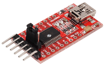
With USB CDC mode we can directly transfer data to and from a PC/mobile device without needing an external USB-to-Serial converter like FT232, CP2102, PL2303, etc. We’ll simply make a virtual COM port. The idea in this demo is to send out on-chip temperature sensor’s temperature reading upon request from a host PC. The request is nothing special but just an ASCII character. The key that was pressed in the host PC’s keyboard is then displayed on an LCD connected with the MSP430.
Code Example
#include "driverlib.h"
#include "delay.h"
#include "lcd.h"
#include "lcd_print.h"

#include "USB_config/descriptors.h"
#include "USB_API/USB_Common/device.h"
#include "USB_API/USB_Common/usb.h"
#include "USB_API/USB_CDC_API/UsbCdc.h"
#include "USB_app/usbConstructs.h"

#include "hal.h"

volatile uint8_t bCDCDataReceived_event = FALSE;

#define RX_BUFFER_SIZE  1
#define TX_BUFFER_SIZE  4

char dataBuffer[RX_BUFFER_SIZE] = "";
char nl[2] = "\n";
uint16_t count;

void ADC12_init(void);
void REF_init(void);

#pragma vector = UNMI_VECTOR
__interrupt void UNMI_ISR (void)
{
    switch (__even_in_range(SYSUNIV, SYSUNIV_BUSIFG ))
    {
        case SYSUNIV_NONE:
            __no_operation();
            break;
        case SYSUNIV_NMIIFG:
            __no_operation();
            break;
        case SYSUNIV_OFIFG:
            UCS_clearFaultFlag(UCS_XT2OFFG);
            UCS_clearFaultFlag(UCS_DCOFFG);
            SFR_clearInterrupt(SFR_OSCILLATOR_FAULT_INTERRUPT);
            break;
        case SYSUNIV_ACCVIFG:
            __no_operation();
            break;
        case SYSUNIV_BUSIFG:
            SYSBERRIV = 0;
            USB_disable();
    }
}

void main (void)
{
    float tmp = 0.0;
    signed int ADC_Count = 0;
    signed long temp = 0;
    uint8_t tc[TX_BUFFER_SIZE] = {0x00, 0x00, '\r', '\n'};

    WDT_A_hold(WDT_A_BASE);

    PMM_setVCore(PMM_CORE_LEVEL_2);

    REF_init();

    ADC12_init();

    LCD_init();
    LCD_clear_home();

    LCD_goto(1, 0);
    LCD_putstr("MSP430 USB CDC");

    LCD_goto(0, 1);
    LCD_putstr("T/'C:");

    LCD_goto(11, 1);
    LCD_putstr("RX:");

    USBHAL_initPorts();
    USBHAL_initClocks(8000000);
    USB_setup(TRUE, TRUE);

    __enable_interrupt();

    while (1)
    {
        uint8_t ReceiveError = 0;
        uint8_t SendError = 0;

        ADC_Count = ADC12_A_getResults(ADC12_A_BASE,
                                       ADC12_A_MEMORY_0);

        tmp = (((float)ADC_Count * 1.5) / 4095.0);
        temp = ((tmp - 0.688) / 0.00252);

        print_C(6, 1, temp);

        switch (USB_getConnectionState())
        {
            case ST_ENUM_ACTIVE:
            {
                __disable_interrupt();
                if (!USBCDC_getBytesInUSBBuffer(CDC0_INTFNUM))
                {
                    __bis_SR_register(LPM0_bits + GIE);
                }

                __enable_interrupt();

                if (bCDCDataReceived_event)
                {
                    bCDCDataReceived_event = FALSE;

                    count = USBCDC_receiveDataInBuffer((uint8_t*)dataBuffer,
                                                       RX_BUFFER_SIZE,
                                                       CDC0_INTFNUM);
                    LCD_goto(15, 1);
                    LCD_putstr(dataBuffer);
                }

                tc[0] = ((temp / 10) + 0x30);
                tc[1] = ((temp % 10) + 0x30);

                if(USBCDC_sendDataInBackground((uint8_t*)tc,
                                               TX_BUFFER_SIZE,
                                               CDC0_INTFNUM,
                                               1))
                {
                    SendError = 0x01;
                    break;
                }

                break;

            }
            case ST_PHYS_DISCONNECTED:
            case ST_ENUM_SUSPENDED:
            case ST_PHYS_CONNECTED_NOENUM_SUSP:
                __bis_SR_register(LPM3_bits + GIE);
                _NOP();
                break;

            case ST_ENUM_IN_PROGRESS:
            default:;
        }

        if (ReceiveError || SendError)
        {
        }
    }
}

void ADC12_init(void)
{
    ADC12_A_configureMemoryParam configureMemoryParam = {0};

    ADC12_A_init(ADC12_A_BASE,
                 ADC12_A_SAMPLEHOLDSOURCE_SC,
                 ADC12_A_CLOCKSOURCE_ACLK,
                 ADC12_A_CLOCKDIVIDER_1);

    ADC12_A_setupSamplingTimer(ADC12_A_BASE,
                               ADC12_A_CYCLEHOLD_768_CYCLES,
                               ADC12_A_CYCLEHOLD_4_CYCLES,
                               ADC12_A_MULTIPLESAMPLESENABLE);

    ADC12_A_setResolution(ADC12_A_BASE,
                          ADC12_A_RESOLUTION_12BIT);

    configureMemoryParam.memoryBufferControlIndex = ADC12_A_MEMORY_0;
    configureMemoryParam.inputSourceSelect = ADC12_A_INPUT_TEMPSENSOR;
    configureMemoryParam.positiveRefVoltageSourceSelect = ADC12_A_VREFPOS_INT;
    configureMemoryParam.negativeRefVoltageSourceSelect = ADC12_A_VREFNEG_AVSS;
    configureMemoryParam.endOfSequence = ADC12_A_NOTENDOFSEQUENCE;

    ADC12_A_configureMemory(ADC12_A_BASE,
                            &configureMemoryParam);

    ADC12_A_enable(ADC12_A_BASE);

    ADC12_A_startConversion(ADC12_A_BASE,
                            ADC12_A_MEMORY_0,
                            ADC12_A_REPEATED_SINGLECHANNEL);
}

void REF_init(void)
{
    while(REF_ACTIVE == Ref_isRefGenBusy(REF_BASE));

    Ref_setReferenceVoltage(REF_BASE,
                            REF_VREF1_5V);

    Ref_enableReferenceVoltage(REF_BASE);

    __delay_cycles(100);
}
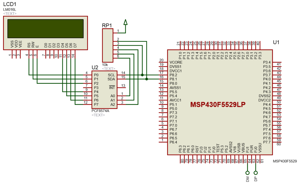
Hardware Setup
Explanation
The setup for using the ADC and on-chip temperature sensor have already been discussed and demoed previously. Likewise, the basic USB setup has been discussed in the USB module overview section. Therefore, I’ll skip these parts. The main loop is the part that is of our interest. As can be seen, temperature read from ADC is shown in the display first. The switch-case statement acts according to the state of the USB module’s connection state. Of these states, the first one (ST_ENUM_ACTIVE) is of most importance. In this state, data is transferred by a method called enumeration. The rest of the states have other importance but these won’t be needed here. The whole system is interrupt driven and so it is necessary to disable interrupts upon a reception event and reenable interrupts after processing them.
while (1)
{
    uint8_t ReceiveError = 0;
    uint8_t SendError = 0;

    ADC_Count = ADC12_A_getResults(ADC12_A_BASE, ADC12_A_MEMORY_0);

    tmp = (((float)ADC_Count * 1.5) / 4095.0);
    temp = ((tmp - 0.688) / 0.00252);

    print_C(6, 1, temp);

    switch (USB_getConnectionState())
    {
        case ST_ENUM_ACTIVE:
        {
            __disable_interrupt();
            if (!USBCDC_getBytesInUSBBuffer(CDC0_INTFNUM))
            {
                __bis_SR_register(LPM0_bits + GIE);
            }

            __enable_interrupt();

            if (bCDCDataReceived_event)
            {
                bCDCDataReceived_event = FALSE;

                count = USBCDC_receiveDataInBuffer((uint8_t*)dataBuffer,
                                                    RX_BUFFER_SIZE,
                                                    CDC0_INTFNUM);
                LCD_goto(15, 1);
                LCD_putstr(dataBuffer);
            }

            tc[0] = ((temp / 10) + 0x30);
            tc[1] = ((temp % 10) + 0x30);

            if(USBCDC_sendDataInBackground((uint8_t*)tc,
                                            TX_BUFFER_SIZE,
                                            CDC0_INTFNUM,
                                            1))
            {
                SendError = 0x01;
                break;
            }

            break;

        }
        case ST_PHYS_DISCONNECTED:
        case ST_ENUM_SUSPENDED:
        case ST_PHYS_CONNECTED_NOENUM_SUSP:
             __bis_SR_register(LPM3_bits + GIE);
             NOP();
             break;

        case ST_ENUM_IN_PROGRESS:
        default:;
    }

    if (ReceiveError || SendError)
    {
    }
}
Out of the all the jargon, the following codes are what that we need to receive and transmit data respectively.
USBCDC_receiveDataInBuffer((uint8_t*)dataBuffer, RX_BUFFER_SIZE, CDC0_INTFNUM);

USBCDC_sendDataInBackground((uint8_t*)tc, TX_BUFFER_SIZE, CDC0_INTFNUM, 1))
The receive function reads received data from CDC0_INTFNUM buffer. This is simply a buffer location that acts bidirectionally. We have to mention the array to which received data needs to be transferred. We also have to mention the size of this array. The transmit function is almost the same as the receive function. Note that all data transactions are done in chunks of bytes. For the sake of simplicity, errors and other USB states are not used. However, when developing a good real-life USB device these should not be ignored.
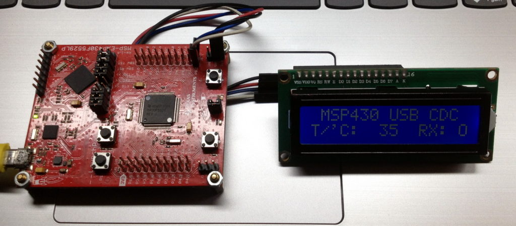
Since it is a USB example, our MSP430 launchpad board needs to be connected with a host PC. Note that no driver installation would be needed for this COM port device as it is a virtual/non-physical COM port and the port number can be any port number.
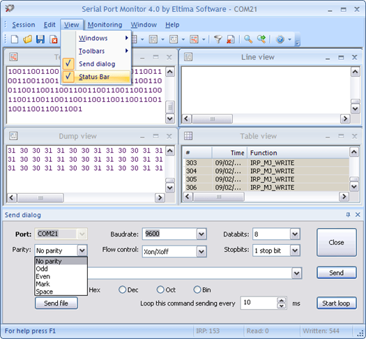
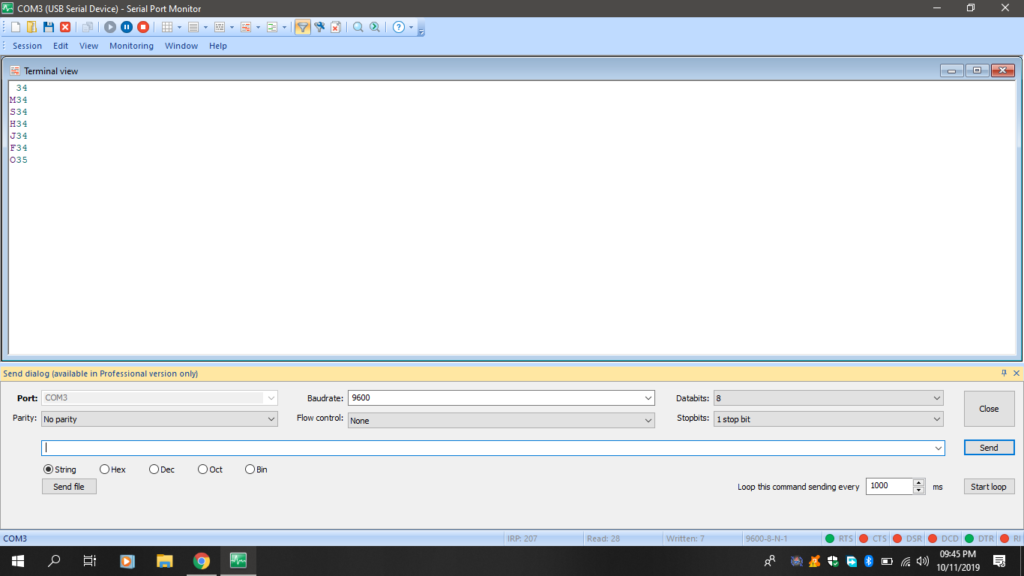
We’ll need a port monitoring terminal software like the Eltima Soft’s Serial Port Monitor.
The demo here works by sending out on-chip temperature sensor’s reading when a keyboard key of the host PC is pressed. The key that was pressed is echoed back.
Demo
|
|
Hello, dear sir Shawon Shahryiar, could you send me the GRACE program by email? I can’t find it anywhere on the Internet. Thank you very much and all the best.
https://www.dropbox.com/scl/fi/6jgmxuuwl9dw2zo9mpuwm/grace_setup_2.2.0.00006.rar?rlkey=gm20hy3odiuyajjow2pas3iz0&st=hhfakdjt&dl=0
Hello, what software are you using for the Hardware setup images and does it support simulation for the MSP430F5529
I used Proteus VSM for drawing schematics but it doesn’t support simulation.
Hi,
Im interfacing MSP430F5529 with MAX17055 fuel guage. while reading 16 bit value, the first byte im receiving is 0. so while reading multiple registers continuously the data exchange is happening, but im getting the correct data. Can anyone suggest me what will be the issue? why im getting 0 in first byte?
read16_bit data code:
uint16_t value = 0;
USCI_B_I2C_setslaveaddress(USCI_B1_BASE, slave_address);
USCI_B_I2C_setmode(USCI_B1_BASE, USCI_B_I2C_TRANSMIT_MODE);
USCI_B_I2C_masterSendStart(USCI_B1_BASE);
while (!USCI_B_I2C_masterSendStart(USCI_B1_BASE));
USCI_B_I2C_mastterSendSingleByte(USCI_B1_BASE, reg_address);
USCI_B_I2C_setslaveaddress(USCI_B1_BASE, slave_address);
USCI_B_I2C_setmode(USCI_B1_BASE, USCI_B_I2C_TRANSMIT_MODE);
USCI_B_I2C_masterReceiveMultiByteStart(USCI_B1_BASE);
uint8_t lb = USCI_B_I2C_masterReceiveMultiByteNext(USCI_B1_BASE);
uint8_t hb = USCI_B_I2C_masterReceiveMultiByteFinish(USCI_B1_BASE);
while (USCI_B_I2C_isBusBusy(USCI_B_BASE));
value = lb << 8;
value |= hb;
return value;
In code, after sending reg address, it will be recieve mode. its a type mistake
Hi, im trying to send the command from the terminal view. i can able to send the command and tried to blink p1.0 led in msp430f5529 controller, its working fine. And im using led driver IS31FL3236A interfaced with msp430f5529 controller, i can able to interface im getting the expected output.
now i need to send the command from seriak monitor based on that command i2c communication need to start. both communication are working fine, when it runs separately. its not working when i tried to combine.
any one had any idea, why it is happening or what will be the issue?
It could be due to:
1. conflicts in clock settings
2. hardware conflict like pin mapping
3. code is getting stuck or waiting for one communication line to finish
4. use of polling method instead of interrupt-driven coding
Hi, thank you for the respose.
Do I need to use different clock initialization for I2C and UART communication? if YES, can you explain how to do that?
I mean check which clock has been set for UART and I2C…. Is it SMCLK, MCLK, etc and is it tuned to right frequency required by the respective hardware?
Is there any example on how to implement polling method in uart?
Why go for polling method when it is a blocking method of coding? It is better to use interrupts instead at least for UART receive.
yes!! currently in my code, only for uart im using interrupts to recieve command from serial monitor. Im not using interrupt for I2C communication.
so the issue is must be in clock initialization. right?
For UART, im using USCI_A1_BASE. and for I2C, im using USCI_B1_BASE.
And another thing i need to ask is, in uart when i tried blink led(p1.0) in msp430f5529 by passing command. here, without clock I’m getting output. how it is possible?
And for both i2c and uart i gave SMCLK with 1Mhz
I am surprised and happy to find this tutorial on the F5529 as TI makes a lot of different devices.
Thank you very much for putting in the extra knowledge in each segment, made reading worthwhile.
Good Work!
lovely tutorial but to be honest I don’t think I’d be investing my time on this board to start with it’s not cheap and readily available as the stm32 boards can you please do more tutorials on stm32 board’s and the stc micros thanks
Hello, I try to program MSP430FR6047 but i get error “the debug interface to the device has been secured”. when flashing using uniflash and when program using CCS this happen. can you help me to solve this problem
You can try “On connect, erase user code and unlock the device” option.
Pingback: Tinkering TI MSP430F5529 – gStore
Hello
I am doing project of msp430g2553 interface(using i2c communication) with temp 100(temperature sensor) and try to read the temperature in dispaly(16*2) but didn’t get the out put (using code composer studio) can u share me any example code for this project
Thank you sir,
Which sensor? Did you use pullup resistors for SDA-SCL pins?
Where is lcd_print.h?
All files and docs are here:
https://libstock.mikroe.com/projects/view/3233/tinkering-ti-msp430f5529
You want the truth? TI makes and sell “underpowered micros”, you know? Low everything, not only the power but also peripherals. So the price is not justified.
Otherwise, if I’ll move there, I’ll introduce them to my small hobby projects – there are still some advantages.
I may even make a visual configuration tool of my own for them…
Yeah the prices of TI products are higher than other manufacturers but I don’t think the hardware peripherals are inferior.
Not inferior but in not enough numbers compared to STM32.
True