Tinkering TI MSP430F5529

|
|
Real Time Clock – RTC_A
As stated before, RTC_A is mainly intended for time keeping and, in this demo, we will see how make a real-time clock with the RTC_A module.
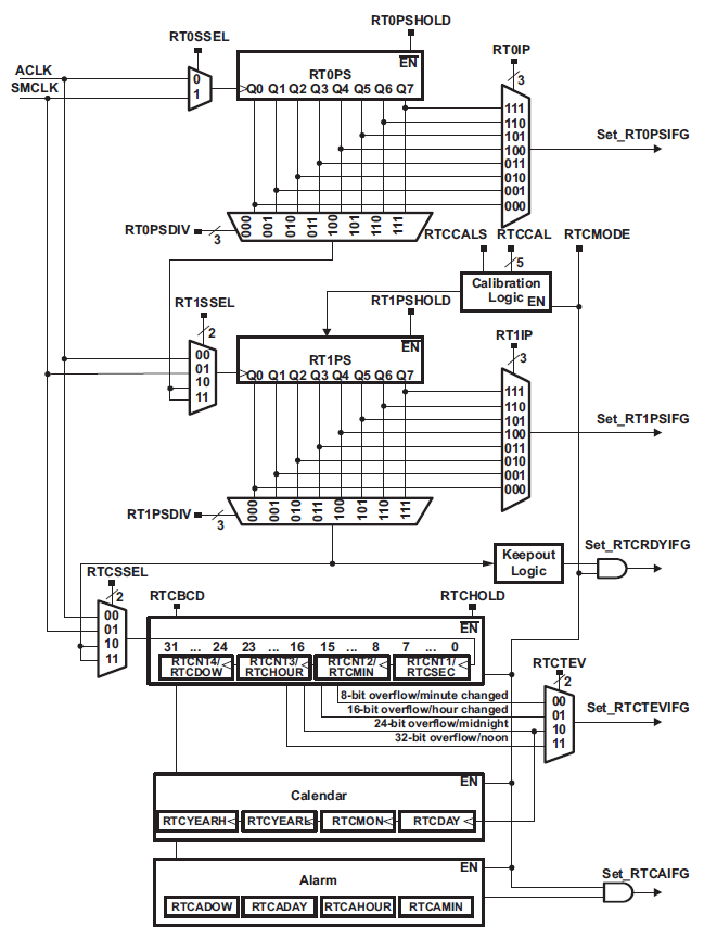
Let’s see some insights of RTC_A module. Firstly, we can see that the RTC_A module can be feed with either SMCLK or ACLK. Since SMCLK has other important uses, it is better to use ACLK for RTC_A. ACLK should have a frequency of 32.768 kHz and to achieve that it is better to use dedicated external crystal or TCXO. The RTC’s counter RTCBCD can be then clocked directly by clock signals or via RTxPS registers. The desired tick period for RTC is obviously 1 Hz. Selectable either in BCD or hexadecimal format, the RTC_A calendar block gives time and date. A cool feature is the fact that internal algorithm takes care of leap-years from the year 1901 AD to 2099 AD. It is also possible to set calendar alarms but coder has to be careful because out-of-range or invalid date-time settings may result in unpredictable behavior. Lastly, there are several interrupts for various timer events.
Code Example
#include "driverlib.h"
#include "delay.h"
#include "lcd.h"
#include "lcd_print.h"
Calendar current_Time;
unsigned char update_time = false;
void clock_init(void);
void GPIO_init(void);
void RTC_init(void);
void display_year(unsigned char x_pos, unsigned char y_pos, unsigned int value);
void display_time_date(unsigned char x_pos, unsigned char y_pos, unsigned char value);
unsigned int change_value(unsigned char x_pos, unsigned char y_pos, signed int value, signed int value_min, signed int value_max, unsigned char value_type);
void set_RTC(void);
#pragma vector = RTC_VECTOR
__interrupt void RTC_A_ISR (void)
{
switch(__even_in_range(RTCIV, 16))
{
case 0: break; //No interrupts
case 2: //RTCRDYIFG
{
GPIO_toggleOutputOnPin(GPIO_PORT_P4,
GPIO_PIN7);
current_Time = RTC_A_getCalendarTime(RTC_A_BASE);
update_time = true;
break;
}
case 4: break; //RTCEVIFG
case 6: break; //RTCAIFG
case 8: break; //RT0PSIFG
case 10: break; //RT1PSIFG
case 12: break; //Reserved
case 14: break; //Reserved
case 16: break; //Reserved
default: break;
}
}
void main(void)
{
WDT_A_hold(WDT_A_BASE);
clock_init();
GPIO_init();
RTC_init();
LCD_init();
LCD_clear_home();
LCD_goto(6, 0);
LCD_putstr(": :");
LCD_goto(5, 1);
LCD_putstr("/ /");
while(1)
{
set_RTC();
if(update_time)
{
display_time_date(4, 0, current_Time.Hours);
display_time_date(7, 0, current_Time.Minutes);
display_time_date(10, 0, current_Time.Seconds);
display_time_date(3, 1, current_Time.DayOfMonth);
display_time_date(6, 1, current_Time.Month);
display_year(9, 1, current_Time.Year);
update_time = 0;
}
};
}
void clock_init(void)
{
PMM_setVCore(PMM_CORE_LEVEL_3);
GPIO_setAsPeripheralModuleFunctionInputPin(GPIO_PORT_P5,
(GPIO_PIN4 | GPIO_PIN2));
GPIO_setAsPeripheralModuleFunctionOutputPin(GPIO_PORT_P5,
(GPIO_PIN5 | GPIO_PIN3));
UCS_setExternalClockSource(XT1_FREQ,
XT2_FREQ);
UCS_turnOnXT2(UCS_XT2_DRIVE_4MHZ_8MHZ);
UCS_turnOnLFXT1(UCS_XT1_DRIVE_3,
UCS_XCAP_3);
UCS_initClockSignal(UCS_FLLREF,
UCS_XT2CLK_SELECT,
UCS_CLOCK_DIVIDER_4);
UCS_initFLLSettle(MCLK_KHZ,
MCLK_FLLREF_RATIO);
UCS_initClockSignal(UCS_SMCLK,
UCS_XT2CLK_SELECT,
UCS_CLOCK_DIVIDER_2);
UCS_initClockSignal(UCS_ACLK,
UCS_XT1CLK_SELECT,
UCS_CLOCK_DIVIDER_1);
}
void GPIO_init(void)
{
GPIO_setAsInputPinWithPullUpResistor(GPIO_PORT_P1,
GPIO_PIN1);
GPIO_setAsInputPinWithPullUpResistor(GPIO_PORT_P2,
GPIO_PIN1);
GPIO_setAsOutputPin(GPIO_PORT_P1,
GPIO_PIN0);
GPIO_setDriveStrength(GPIO_PORT_P1,
GPIO_PIN0,
GPIO_FULL_OUTPUT_DRIVE_STRENGTH);
GPIO_setAsOutputPin(GPIO_PORT_P4,
GPIO_PIN7);
GPIO_setDriveStrength(GPIO_PORT_P4,
GPIO_PIN7,
GPIO_FULL_OUTPUT_DRIVE_STRENGTH);
}
void RTC_init(void)
{
current_Time.Seconds = 30;
current_Time.Minutes = 10;
current_Time.Hours = 10;
current_Time.DayOfWeek = 1;
current_Time.DayOfMonth = 1;
current_Time.Month = 1;
current_Time.Year = 2000;
RTC_A_initCalendar(RTC_A_BASE,
¤t_Time,
RTC_A_FORMAT_BINARY);
RTC_A_setCalendarEvent(RTC_A_BASE,
RTC_A_CALENDAREVENT_MINUTECHANGE);
RTC_A_clearInterrupt(RTC_A_BASE,
(RTCRDYIFG | RTCTEVIFG | RTCAIFG));
RTC_A_enableInterrupt(RTC_A_BASE,
(RTCRDYIE | RTCTEVIE | RTCAIE));
RTC_A_startClock(RTC_A_BASE);
__enable_interrupt();
}
void display_year(unsigned char x_pos, unsigned char y_pos, unsigned int value)
{
unsigned char tmp = 0;
tmp = (value / 100);
display_time_date(x_pos, y_pos, tmp);
tmp = (value % 100);
display_time_date((x_pos + 2), y_pos, tmp);
}
void display_time_date(unsigned char x_pos, unsigned char y_pos, unsigned char value)
{
unsigned char ch = 0;
ch = (value / 10);
LCD_goto(x_pos, y_pos);
LCD_putchar((ch + 0x30));
ch = (value % 10);
LCD_goto((1 + x_pos), y_pos);
LCD_putchar((ch + 0x30));
}
unsigned int change_value(unsigned char x_pos, unsigned char y_pos, signed int value, signed int value_min, signed int value_max, unsigned char value_type)
{
while(1)
{
LCD_goto(x_pos, y_pos);
switch(value_type)
{
case 1:
{
LCD_putstr(" ");
break;
}
default:
{
LCD_putstr(" ");
break;
}
}
delay_ms(60);
if(GPIO_getInputPinValue(GPIO_PORT_P1,
GPIO_PIN1) == false)
{
value++;
}
if(value > value_max)
{
value = value_min;
}
switch(value_type)
{
case 1:
{
display_year(x_pos, y_pos, ((unsigned int)value));
break;
}
default:
{
display_time_date(x_pos, y_pos, ((unsigned char)value));
break;
}
}
delay_ms(90);
if(GPIO_getInputPinValue(GPIO_PORT_P2,
GPIO_PIN1) == false)
{
while(GPIO_getInputPinValue(GPIO_PORT_P2,
GPIO_PIN1) == false);
delay_ms(200);
return value;
}
};
}
void set_RTC(void)
{
if(GPIO_getInputPinValue(GPIO_PORT_P2,
GPIO_PIN1) == false)
{
GPIO_setOutputHighOnPin(GPIO_PORT_P1,
GPIO_PIN0);
while(GPIO_getInputPinValue(GPIO_PORT_P2,
GPIO_PIN1) == false);
RTC_A_disableInterrupt(RTC_A_BASE,
(RTCRDYIE | RTCTEVIE | RTCAIE));
RTC_A_holdClock(RTC_A_BASE);
__disable_interrupt();
update_time = false;
current_Time.Hours = change_value(4, 0, current_Time.Hours, 0, 23, 0);
current_Time.Minutes = change_value(7, 0, current_Time.Minutes, 0, 59, 0);
current_Time.Seconds = change_value(10, 0, current_Time.Seconds, 0, 59, 0);
current_Time.DayOfMonth = change_value(3, 1, current_Time.DayOfMonth, 1, 31, 0);
current_Time.Month = change_value(6, 1, current_Time.Month, 1, 12, 0);
current_Time.Year = change_value(9, 1, current_Time.Year, 1970, 2099, 1);
GPIO_setOutputLowOnPin(GPIO_PORT_P1,
GPIO_PIN0);
RTC_A_initCalendar(RTC_A_BASE,
¤t_Time,
RTC_A_FORMAT_BINARY);
RTC_A_clearInterrupt(RTC_A_BASE,
(RTCRDYIFG | RTCTEVIFG | RTCAIFG));
RTC_A_enableInterrupt(RTC_A_BASE,
(RTCRDYIE | RTCTEVIE | RTCAIE));
RTC_A_startClock(RTC_A_BASE);
__enable_interrupt();
}
}
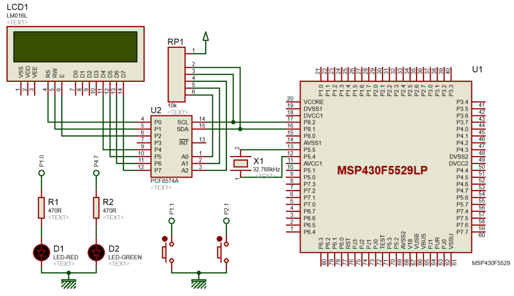
Hardware Setup
Explanation
Earlier I mentioned why we should use ACLK for RTC and so for that ground I used ACLK to drive the RTC_A module. On board external 32.768 kHz crystal is used for ACLK as it is better than any other source.
UCS_initClockSignal(UCS_ACLK, UCS_XT1CLK_SELECT, UCS_CLOCK_DIVIDER_1);
On-board LEDs and buttons are also used. P4.7 LED is used as second ticker while P1.0 LED is used as setting mode indicator. P1.1 button is used as a modifier button while P2.1 button acts as a set/enter button.
GPIO_setAsInputPinWithPullUpResistor(GPIO_PORT_P1, GPIO_PIN1);
GPIO_setAsInputPinWithPullUpResistor(GPIO_PORT_P2, GPIO_PIN1);

GPIO_setAsOutputPin(GPIO_PORT_P1, GPIO_PIN0);
GPIO_setAsOutputPin(GPIO_PORT_P4, GPIO_PIN7);
Now let’s see how the RTC is set up.
void RTC_init(void)
{
current_Time.Seconds = 30;
current_Time.Minutes = 10;
current_Time.Hours = 10;
current_Time.DayOfWeek = 1;
current_Time.DayOfMonth = 1;
current_Time.Month = 1;
current_Time.Year = 2000;
RTC_A_initCalendar(RTC_A_BASE, ¤t_Time, RTC_A_FORMAT_BINARY);
RTC_A_setCalendarEvent(RTC_A_BASE, RTC_A_CALENDAREVENT_MINUTECHANGE);
RTC_A_clearInterrupt(RTC_A_BASE, (RTCRDYIFG | RTCTEVIFG | RTCAIFG));
RTC_A_enableInterrupt(RTC_A_BASE, (RTCRDYIE | RTCTEVIE | RTCAIE));
RTC_A_startClock(RTC_A_BASE);
__enable_interrupt();
}
We start by initializing and loading date-time parameters of our choosing in binary format. We chose binary format because in that way we can avoid unnecessary BCD-to-binary conversions. Finally, we enable required interrupts after clearing them and start the RTC.
Inside the interrupt vector, we just check the RTCRDY interrupt flag and that’s because from here we will extract current RTC time info. Other interrupts, although enabled, are not needed as we are not using alarm and event features.
#pragma vector = RTC_VECTOR
__interrupt void RTC_A_ISR (void)
{
    switch(__even_in_range(RTCIV, 16))
    {
        case 0: break;  //No interrupts
        case 2:         //RTCRDYIFG
        {
            GPIO_toggleOutputOnPin(GPIO_PORT_P4,
                                   GPIO_PIN7);

            current_Time = RTC_A_getCalendarTime(RTC_A_BASE);

            update_time = true;

            break;
        }
        case 4: break;  //RTCEVIFG
        case 6: break;  //RTCAIFG
        case 8: break;  //RT0PSIFG
        case 10: break; //RT1PSIFG
        case 12: break; //Reserved
        case 14: break; //Reserved
        case 16: break; //Reserved
        default: break;
    }
}
In the main loop, we can do two things, either we can set time or watch it. When setting date-time, the display only shows the date-time parameters we are setting. After setup up, the RTC module is reinitialized with new date and time.
set_RTC();

if(update_time)
{
   display_time_date(4, 0, current_Time.Hours);
   display_time_date(7, 0, current_Time.Minutes);
   display_time_date(10, 0, current_Time.Seconds);
   display_time_date(3, 1, current_Time.DayOfMonth);
   display_time_date(6, 1, current_Time.Month);
   display_year(9, 1, current_Time.Year);
   update_time = 0;
}
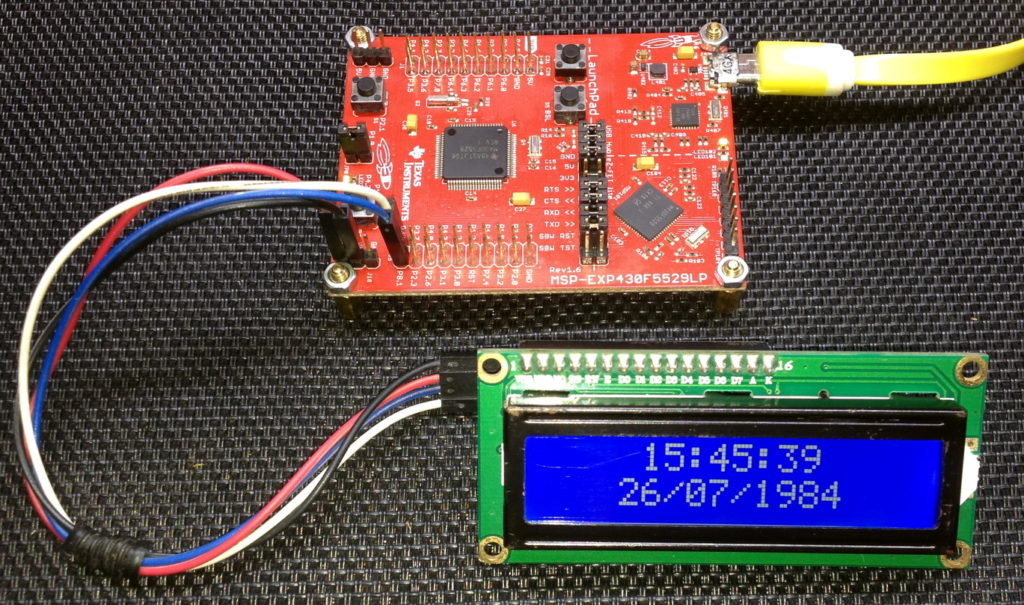
Demo
|
|
Hello, dear sir Shawon Shahryiar, could you send me the GRACE program by email? I can’t find it anywhere on the Internet. Thank you very much and all the best.
https://www.dropbox.com/scl/fi/6jgmxuuwl9dw2zo9mpuwm/grace_setup_2.2.0.00006.rar?rlkey=gm20hy3odiuyajjow2pas3iz0&st=hhfakdjt&dl=0
Hello, what software are you using for the Hardware setup images and does it support simulation for the MSP430F5529
I used Proteus VSM for drawing schematics but it doesn’t support simulation.
Hi,
Im interfacing MSP430F5529 with MAX17055 fuel guage. while reading 16 bit value, the first byte im receiving is 0. so while reading multiple registers continuously the data exchange is happening, but im getting the correct data. Can anyone suggest me what will be the issue? why im getting 0 in first byte?
read16_bit data code:
uint16_t value = 0;
USCI_B_I2C_setslaveaddress(USCI_B1_BASE, slave_address);
USCI_B_I2C_setmode(USCI_B1_BASE, USCI_B_I2C_TRANSMIT_MODE);
USCI_B_I2C_masterSendStart(USCI_B1_BASE);
while (!USCI_B_I2C_masterSendStart(USCI_B1_BASE));
USCI_B_I2C_mastterSendSingleByte(USCI_B1_BASE, reg_address);
USCI_B_I2C_setslaveaddress(USCI_B1_BASE, slave_address);
USCI_B_I2C_setmode(USCI_B1_BASE, USCI_B_I2C_TRANSMIT_MODE);
USCI_B_I2C_masterReceiveMultiByteStart(USCI_B1_BASE);
uint8_t lb = USCI_B_I2C_masterReceiveMultiByteNext(USCI_B1_BASE);
uint8_t hb = USCI_B_I2C_masterReceiveMultiByteFinish(USCI_B1_BASE);
while (USCI_B_I2C_isBusBusy(USCI_B_BASE));
value = lb << 8;
value |= hb;
return value;
In code, after sending reg address, it will be recieve mode. its a type mistake
Hi, im trying to send the command from the terminal view. i can able to send the command and tried to blink p1.0 led in msp430f5529 controller, its working fine. And im using led driver IS31FL3236A interfaced with msp430f5529 controller, i can able to interface im getting the expected output.
now i need to send the command from seriak monitor based on that command i2c communication need to start. both communication are working fine, when it runs separately. its not working when i tried to combine.
any one had any idea, why it is happening or what will be the issue?
It could be due to:
1. conflicts in clock settings
2. hardware conflict like pin mapping
3. code is getting stuck or waiting for one communication line to finish
4. use of polling method instead of interrupt-driven coding
Hi, thank you for the respose.
Do I need to use different clock initialization for I2C and UART communication? if YES, can you explain how to do that?
I mean check which clock has been set for UART and I2C…. Is it SMCLK, MCLK, etc and is it tuned to right frequency required by the respective hardware?
Is there any example on how to implement polling method in uart?
Why go for polling method when it is a blocking method of coding? It is better to use interrupts instead at least for UART receive.
yes!! currently in my code, only for uart im using interrupts to recieve command from serial monitor. Im not using interrupt for I2C communication.
so the issue is must be in clock initialization. right?
For UART, im using USCI_A1_BASE. and for I2C, im using USCI_B1_BASE.
And another thing i need to ask is, in uart when i tried blink led(p1.0) in msp430f5529 by passing command. here, without clock I’m getting output. how it is possible?
And for both i2c and uart i gave SMCLK with 1Mhz
I am surprised and happy to find this tutorial on the F5529 as TI makes a lot of different devices.
Thank you very much for putting in the extra knowledge in each segment, made reading worthwhile.
Good Work!
lovely tutorial but to be honest I don’t think I’d be investing my time on this board to start with it’s not cheap and readily available as the stm32 boards can you please do more tutorials on stm32 board’s and the stc micros thanks
Hello, I try to program MSP430FR6047 but i get error “the debug interface to the device has been secured”. when flashing using uniflash and when program using CCS this happen. can you help me to solve this problem
You can try “On connect, erase user code and unlock the device” option.
Pingback: Tinkering TI MSP430F5529 – gStore
Hello
I am doing project of msp430g2553 interface(using i2c communication) with temp 100(temperature sensor) and try to read the temperature in dispaly(16*2) but didn’t get the out put (using code composer studio) can u share me any example code for this project
Thank you sir,
Which sensor? Did you use pullup resistors for SDA-SCL pins?
Where is lcd_print.h?
All files and docs are here:
https://libstock.mikroe.com/projects/view/3233/tinkering-ti-msp430f5529
You want the truth? TI makes and sell “underpowered micros”, you know? Low everything, not only the power but also peripherals. So the price is not justified.
Otherwise, if I’ll move there, I’ll introduce them to my small hobby projects – there are still some advantages.
I may even make a visual configuration tool of my own for them…
Yeah the prices of TI products are higher than other manufacturers but I don’t think the hardware peripherals are inferior.
Not inferior but in not enough numbers compared to STM32.
True