Tinkering TI MSP430F5529

|
|
Hardware Multiplier Module – MPY32
Many high-end microcontrollers consist of internal hardware multiplier. So, what does this hardware do? Well a multiplier performs multiplication and simply that’s it. Why is it important to have a hardware multiplier when we are coding in high-level C language and simple multiplication instruction is enough to do the job? Without hardware multiplier, multiplication is made possible by complex coding, i.e. by hidden software methods. Unlike dedicated hardware, software method takes time and uses resources since it is an emulated task. It is more like hardware rendering vs software rendering. We tend to like good graphics while playing games. A general-purpose computer without a dedicated graphics card may not properly run a game that has good graphical details. A gaming computer, on the other hand, has a dedicated graphics card and it can run the game with best performance. Just like the graphics card, a hardware multiplier is such a necessary hardware renderer that is often needed in time-limited complex computations and digital signal processing (DSP).
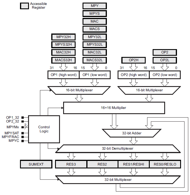
MSP430F5529 has a 32-bit hardware multiplier named MPY32. Like DMA, it is not a part of the CPU and so it won’t affect the operations of the CPU when used. However, the CPU is needed to load and extract data from the multiplier. It supports the following multiplications:
• Unsigned multiply
• Signed multiply
• Unsigned multiply accumulate
• Signed multiply accumulate
• 8-bit, 16-bit, 24-bit, and 32-bit operands
• Saturation
• Fractional numbers
• 8-bit and 16-bit operation compatible with 16-bit hardware multiplier
• 8-bit and 24-bit multiplications without requiring a “sign extend” instruction
Software-based multiplication utilizes CPU and keeps it busy. Software multiplication is like repetitive addition. We don’t see it happening because the whole process is done in machine/assembly language level while we are coding in high-level C language.
Code Example
#include "driverlib.h"
#include "delay.h"
#include "lcd.h"
#include "lcd_print.h"

void clock_init(void);
void timer_T0A5_init(void);

void main(void)
{
    unsigned int i = 0;
    unsigned int j = 0;

    signed long res = 0;
    signed int num1 = 263;
    signed int num2 = 249;
    unsigned int timer_count = 0;

    WDT_A_hold(WDT_A_BASE);

    clock_init();
    timer_T0A5_init();

    LCD_init();
    LCD_clear_home();

    LCD_goto(4, 0);
    LCD_putstr("Software");
    LCD_goto(1, 1);
    LCD_putstr("Multiplication");

    delay_ms(2000);
    LCD_clear_home();

    LCD_goto(0, 0);
    LCD_putstr("263(x)249=");
    LCD_goto(0, 1);
    LCD_putstr("T.CNT = ");

    Timer_A_startCounter(__MSP430_BASEADDRESS_T0A5__,
                         TIMER_A_CONTINUOUS_MODE);

    for(i = 0; i < num1; i++)
    {
        for(j = 0; j < num2; j++)
        {
            res++;
        }
    }

    timer_count = Timer_A_getCounterValue(__MSP430_BASEADDRESS_T0A5__);

    Timer_A_stop(__MSP430_BASEADDRESS_T0A5__);

    print_I(10, 0, res);
    print_I(10, 1, timer_count);

    delay_ms(4000);
    LCD_clear_home();

    res = 0;
    timer_count = 0;
    Timer_A_clear(__MSP430_BASEADDRESS_T0A5__);

    LCD_goto(4, 0);
    LCD_putstr("Hardware");
    LCD_goto(1, 1);
    LCD_putstr("Multiplication");

    delay_ms(2000);
    LCD_clear_home();

    LCD_goto(0, 0);
    LCD_putstr("263(x)249=");
    LCD_goto(0, 1);
    LCD_putstr("T.CNT = ");

    Timer_A_startCounter(__MSP430_BASEADDRESS_T0A5__,
                         TIMER_A_CONTINUOUS_MODE);

    MPY32_setOperandOne16Bit(MPY32_MULTIPLY_UNSIGNED,
                             num1);

    MPY32_setOperandTwo16Bit(num2);

    res = MPY32_getResult();

    timer_count = Timer_A_getCounterValue(__MSP430_BASEADDRESS_T0A5__);

    Timer_A_stop(__MSP430_BASEADDRESS_T0A5__);

    print_I(10, 0, res);
    print_I(10, 1, timer_count);

    delay_ms(4000);

    num1 = -99;
    num2 = 660;

    LCD_clear_home();

    LCD_goto(0, 0);
    LCD_putstr("Signed Software");
    LCD_goto(1, 1);
    LCD_putstr("Multiplication");

    delay_ms(2000);
    LCD_clear_home();

    LCD_goto(0, 0);
    LCD_putstr("-99(x)660=");
    LCD_goto(0, 1);
    LCD_putstr("T.CNT = ");

    Timer_A_startCounter(__MSP430_BASEADDRESS_T0A5__,
                         TIMER_A_CONTINUOUS_MODE);

    res = (((signed long)num1) * ((signed long)num2));

    timer_count = Timer_A_getCounterValue(__MSP430_BASEADDRESS_T0A5__);

    Timer_A_stop(__MSP430_BASEADDRESS_T0A5__);

    print_I(10, 0, res);
    print_I(10, 1, timer_count);

    delay_ms(4000);
    LCD_clear_home();

    res = 0;
    timer_count = 0;

    Timer_A_clear(__MSP430_BASEADDRESS_T0A5__);

    LCD_goto(0, 0);
    LCD_putstr("Signed Hardware");
    LCD_goto(1, 1);
    LCD_putstr("Multiplication");

    delay_ms(2000);
    LCD_clear_home();

    LCD_goto(0, 0);
    LCD_putstr("-99(x)660=");
    LCD_goto(0, 1);
    LCD_putstr("T.CNT = ");

    Timer_A_startCounter(__MSP430_BASEADDRESS_T0A5__,
                         TIMER_A_CONTINUOUS_MODE);

    MPY32_setOperandOne16Bit(MPY32_MULTIPLY_SIGNED,
                             num1);

    MPY32_setOperandTwo16Bit(num2);

    res = MPY32_getResult();

    timer_count = Timer_A_getCounterValue(__MSP430_BASEADDRESS_T0A5__);

    Timer_A_stop(__MSP430_BASEADDRESS_T0A5__);

    print_I(10, 0, res);
    print_I(10, 1, timer_count);

    while(1)
    {
    };
}

void clock_init(void)
{
    PMM_setVCore(PMM_CORE_LEVEL_3);

    GPIO_setAsPeripheralModuleFunctionInputPin(GPIO_PORT_P5,
                                               (GPIO_PIN4 | GPIO_PIN2));

    GPIO_setAsPeripheralModuleFunctionOutputPin(GPIO_PORT_P5,
                                                (GPIO_PIN5 | GPIO_PIN3));

    UCS_setExternalClockSource(XT1_FREQ,
                               XT2_FREQ);

    UCS_turnOnXT2(UCS_XT2_DRIVE_4MHZ_8MHZ);

    UCS_turnOnLFXT1(UCS_XT1_DRIVE_3,
                    UCS_XCAP_3);

    UCS_initClockSignal(UCS_FLLREF,
                        UCS_XT2CLK_SELECT,
                        UCS_CLOCK_DIVIDER_4);

    UCS_initFLLSettle(MCLK_KHZ,
                      MCLK_FLLREF_RATIO);

    UCS_initClockSignal(UCS_SMCLK,
                        UCS_XT2CLK_SELECT,
                        UCS_CLOCK_DIVIDER_1);

    UCS_initClockSignal(UCS_ACLK,
                        UCS_XT1CLK_SELECT,
                        UCS_CLOCK_DIVIDER_1);
}

void timer_T0A5_init(void)
{
    Timer_A_initContinuousModeParam ContinuousModeParam =
    {
         TIMER_A_CLOCKSOURCE_SMCLK,
         TIMER_A_CLOCKSOURCE_DIVIDER_1,
         TIMER_A_TAIE_INTERRUPT_DISABLE,
         TIMER_A_DO_CLEAR,
         false
    };

    Timer_A_stop(__MSP430_BASEADDRESS_T0A5__);

    Timer_A_initContinuousMode(__MSP430_BASEADDRESS_T0A5__,
                               &ContinuousModeParam);
}
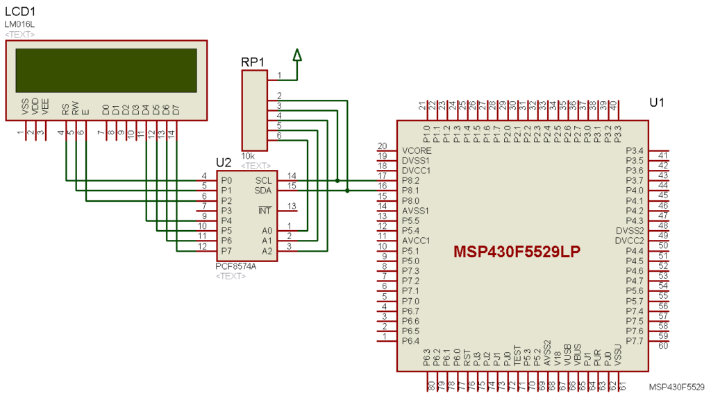
Hardware Setup
Explanation
For demoing the merits of having hardware multiplier, I coded a simple program that simply performs certain calculations and keep record of time count as to determine how long it took to perform the calculations. Two sorts of multiplications are performed both using hardware module and by software means. Same numbers are used in both cases. Timer TA0 is set with SMCLK having XT2_CLK source and no division. Thus, it is running at 4 MHz speed. No interrupt is used to keep things simple. The measure of time is taken as timer ticks and not as actual time in seconds or other units. The larger the value of ticks the longer is the time it took to perform a given calculation. The timer is started right before performing a calculation and stopped immediately after completing it.
void timer_T0A5_init(void)
{
    Timer_A_initContinuousModeParam ContinuousModeParam =
    {
         TIMER_A_CLOCKSOURCE_SMCLK,
         TIMER_A_CLOCKSOURCE_DIVIDER_1,
         TIMER_A_TAIE_INTERRUPT_DISABLE,
         TIMER_A_DO_CLEAR,
         false
    };

    Timer_A_stop(__MSP430_BASEADDRESS_T0A5__);

    Timer_A_initContinuousMode(__MSP430_BASEADDRESS_T0A5__,
                               &ContinuousModeParam);
}
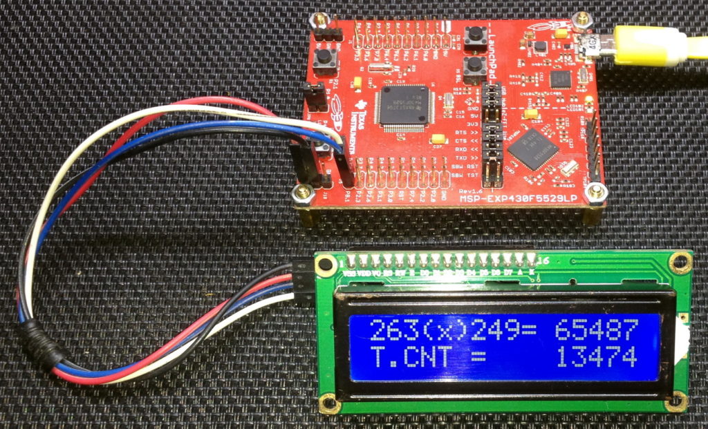
The first calculation is an unsigned multiplication of numbers 263 and 249. As I stated before software multiplication is simply repetitive addition and the code below does exactly that:
for(i = 0; i < num1; i++)
{
    for(j = 0; j < num2; j++)
    {
        res++;
    }
}
The numbers to be multiplied form loops and a variable called res is incremented on each loop passes. This, in effect, behaves like a rudimentary multiplication. The result of this multiplication is 65487. It is revealed that this calculation takes about 13500 counts or about 3 ms.
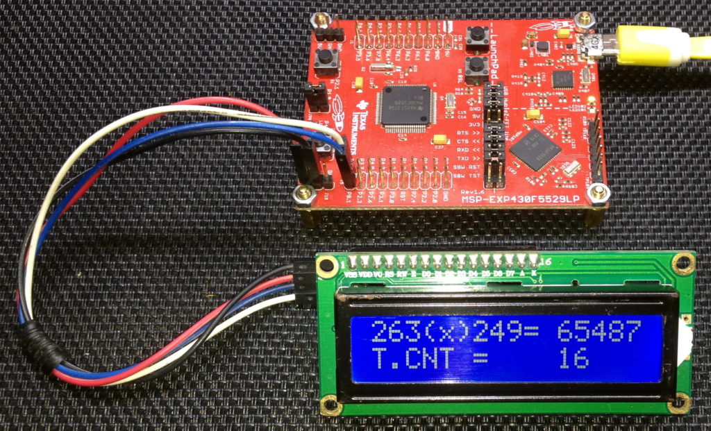
The timer is cleared and restarted. This time however the hardware multiplier is used to multiply the same numbers again.
MPY32_setOperandOne16Bit(MPY32_MULTIPLY_UNSIGNED,
                         num1);

MPY32_setOperandTwo16Bit(num2);

res = MPY32_getResult();
It is found that this time the same calculation takes just 17 ticks or about 4 µs. This shows that hardware multiplication is roughly 750 times faster than software multiplication.
The same is done once more but this time using signed software multiplication of numbers -99 and 660. This time however compiler’s multiplication operator is used. The result of this calculation is -65340. It is found that it takes 36 timer ticks or 9 µs.
res = (((signed long)num1) * ((signed long)num2));
Again, the hardware multiplier is used for computing the same calculation and again it took 17 ticks or about 4 µs. Unlike the first example with unsigned numbers, the time difference is small this time because when the compiler sees multiplication operator, it performs multiplication in assembly/ machine language level. Thus, time is reduced significantly but still it is not as fast as hardware-based multiplication.
Demo


|
|
Hello, dear sir Shawon Shahryiar, could you send me the GRACE program by email? I can’t find it anywhere on the Internet. Thank you very much and all the best.
https://www.dropbox.com/scl/fi/6jgmxuuwl9dw2zo9mpuwm/grace_setup_2.2.0.00006.rar?rlkey=gm20hy3odiuyajjow2pas3iz0&st=hhfakdjt&dl=0
Hello, what software are you using for the Hardware setup images and does it support simulation for the MSP430F5529
I used Proteus VSM for drawing schematics but it doesn’t support simulation.
Hi,
Im interfacing MSP430F5529 with MAX17055 fuel guage. while reading 16 bit value, the first byte im receiving is 0. so while reading multiple registers continuously the data exchange is happening, but im getting the correct data. Can anyone suggest me what will be the issue? why im getting 0 in first byte?
read16_bit data code:
uint16_t value = 0;
USCI_B_I2C_setslaveaddress(USCI_B1_BASE, slave_address);
USCI_B_I2C_setmode(USCI_B1_BASE, USCI_B_I2C_TRANSMIT_MODE);
USCI_B_I2C_masterSendStart(USCI_B1_BASE);
while (!USCI_B_I2C_masterSendStart(USCI_B1_BASE));
USCI_B_I2C_mastterSendSingleByte(USCI_B1_BASE, reg_address);
USCI_B_I2C_setslaveaddress(USCI_B1_BASE, slave_address);
USCI_B_I2C_setmode(USCI_B1_BASE, USCI_B_I2C_TRANSMIT_MODE);
USCI_B_I2C_masterReceiveMultiByteStart(USCI_B1_BASE);
uint8_t lb = USCI_B_I2C_masterReceiveMultiByteNext(USCI_B1_BASE);
uint8_t hb = USCI_B_I2C_masterReceiveMultiByteFinish(USCI_B1_BASE);
while (USCI_B_I2C_isBusBusy(USCI_B_BASE));
value = lb << 8;
value |= hb;
return value;
In code, after sending reg address, it will be recieve mode. its a type mistake
Hi, im trying to send the command from the terminal view. i can able to send the command and tried to blink p1.0 led in msp430f5529 controller, its working fine. And im using led driver IS31FL3236A interfaced with msp430f5529 controller, i can able to interface im getting the expected output.
now i need to send the command from seriak monitor based on that command i2c communication need to start. both communication are working fine, when it runs separately. its not working when i tried to combine.
any one had any idea, why it is happening or what will be the issue?
It could be due to:
1. conflicts in clock settings
2. hardware conflict like pin mapping
3. code is getting stuck or waiting for one communication line to finish
4. use of polling method instead of interrupt-driven coding
Hi, thank you for the respose.
Do I need to use different clock initialization for I2C and UART communication? if YES, can you explain how to do that?
I mean check which clock has been set for UART and I2C…. Is it SMCLK, MCLK, etc and is it tuned to right frequency required by the respective hardware?
Is there any example on how to implement polling method in uart?
Why go for polling method when it is a blocking method of coding? It is better to use interrupts instead at least for UART receive.
yes!! currently in my code, only for uart im using interrupts to recieve command from serial monitor. Im not using interrupt for I2C communication.
so the issue is must be in clock initialization. right?
For UART, im using USCI_A1_BASE. and for I2C, im using USCI_B1_BASE.
And another thing i need to ask is, in uart when i tried blink led(p1.0) in msp430f5529 by passing command. here, without clock I’m getting output. how it is possible?
And for both i2c and uart i gave SMCLK with 1Mhz
I am surprised and happy to find this tutorial on the F5529 as TI makes a lot of different devices.
Thank you very much for putting in the extra knowledge in each segment, made reading worthwhile.
Good Work!
lovely tutorial but to be honest I don’t think I’d be investing my time on this board to start with it’s not cheap and readily available as the stm32 boards can you please do more tutorials on stm32 board’s and the stc micros thanks
Hello, I try to program MSP430FR6047 but i get error “the debug interface to the device has been secured”. when flashing using uniflash and when program using CCS this happen. can you help me to solve this problem
You can try “On connect, erase user code and unlock the device” option.
Pingback: Tinkering TI MSP430F5529 – gStore
Hello
I am doing project of msp430g2553 interface(using i2c communication) with temp 100(temperature sensor) and try to read the temperature in dispaly(16*2) but didn’t get the out put (using code composer studio) can u share me any example code for this project
Thank you sir,
Which sensor? Did you use pullup resistors for SDA-SCL pins?
Where is lcd_print.h?
All files and docs are here:
https://libstock.mikroe.com/projects/view/3233/tinkering-ti-msp430f5529
You want the truth? TI makes and sell “underpowered micros”, you know? Low everything, not only the power but also peripherals. So the price is not justified.
Otherwise, if I’ll move there, I’ll introduce them to my small hobby projects – there are still some advantages.
I may even make a visual configuration tool of my own for them…
Yeah the prices of TI products are higher than other manufacturers but I don’t think the hardware peripherals are inferior.
Not inferior but in not enough numbers compared to STM32.
True