Tinkering TI MSP430F5529

|
|
Timer Overview
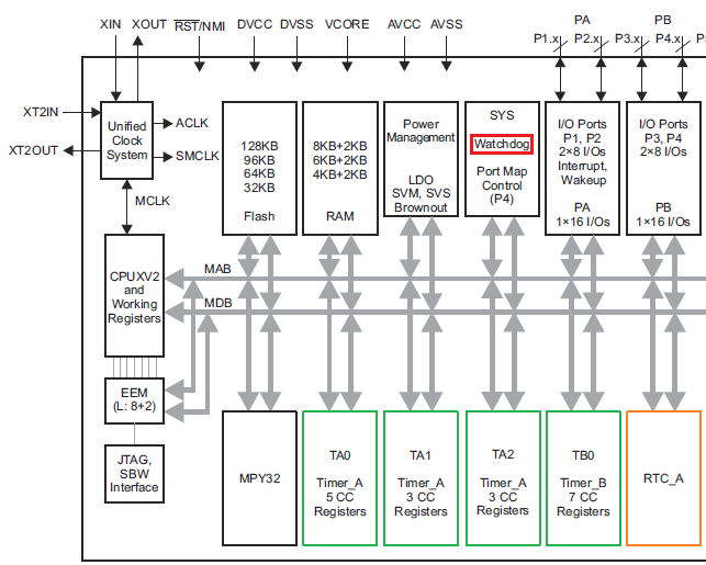
MSP430F5529 microcontroller has six timers divided in three categories – General Purpose Timers like Timer A and Timer B, Watchdog Timer (WDT) and Real Time Clock (RTC).
There are
- 3 Timer As – T0A5, T1A3 and T2A3
- 1 Timer B – T0B7
- 1 WDT_A
- 1 RTC_A
The cut-away block diagram of MSP430F5529’s internal peripherals shown below highlights these timers.
Timer A and Timer B are almost same with minor differences. Timer B offers better PWM options. As their names suggest, RTC_A and WDTA_A are specialized timers for specific or special purposes. They can be alternatively used like regular timers with some limitations.
These timers can be fed with bewildering number of clock combinations offered by the UCS. There are options for external sources in some cases too. The structures and the operations of all of these timers is similar to what we have seen in my previous MSP430 tutorial. The only exception is the RTC_A module as this timer was not available then. Before trying to use any timer, it is my recommendation to go through the driverlib files of the respective timer. This will enable visualizing what can and cannot be done with a given timer module. This also reduces time to read technical documents and datasheet. However, I will still recommend reading these docs should one want to master the timers.
Timer A and B are 16-bit general-purpose timers with capture-compare (CC) modules. The CC modules can be used for either capturing waveforms or PWM/waveform generations. If CC modules are not needed, these timers can be used for timing events and keeping track of time. In TI’s literature, we will see that timers are named as TxYn where Y represents timer class/category, i.e. Timer A, Timer B, etc, x represents timer number or instantiation and n represents number of CC channels. Therefore, T0A5 means 0th instantiation of Timer A having 5 CC channels or simply 0th A-type timer having 5 CC channels. Sometimes, the CC channels are ignored and the timers are simply named like TA2. This naming states 2nd instantiation of Timer A or simply 2nd A-type Timer. Thus, there is a short naming format and a long naming format for general purpose timers.
MSP430x5xxx and MSP430x6xxx family of microcontrollers have three types of RTCs and they vary slightly in some features. MSP430F5529 has one RTC_A module which is the basic of all three types. RTC_A lacks battery-backup option unlike other RTCs. RTC_A is a special timer with a 32-bit counter that is intended for time-keeping applications, i.e., clock and calendar. Since time-keeping needs to be very accurate, RTC has special hardware arrangements to take care of so. It is my personal recommendation to use dedicated 32.768 kHz temperature-compensated crystal oscillator (TCXO) as the source of RTC_A clock. This will ensure better accuracy and precision. It is a common problem for most RTCs to either lead ahead or lack behind actual time. RTC_A can also be used as a 32-bit timer if time-keeping is not needed. However, there are no hardware CC channels with RTC_A.
WDT_A is similar but more advanced than the WDT+ seen in my previous MSP430 tutorial. It has 8 timer intervals rather than 4. This special timer is primarily intended for avoiding erratic/irresponsive behaviour in the event of an electromagnetic interference (EMI) or conditions that leave a micro into an unforeseen loop or other software issue. Again, this timer can be alternatively used like a regular timer if watchdog feature is not needed. However, this timer too doesn’t have any CC channel.
|
|
Hello, dear sir Shawon Shahryiar, could you send me the GRACE program by email? I can’t find it anywhere on the Internet. Thank you very much and all the best.
https://www.dropbox.com/scl/fi/6jgmxuuwl9dw2zo9mpuwm/grace_setup_2.2.0.00006.rar?rlkey=gm20hy3odiuyajjow2pas3iz0&st=hhfakdjt&dl=0
Hello, what software are you using for the Hardware setup images and does it support simulation for the MSP430F5529
I used Proteus VSM for drawing schematics but it doesn’t support simulation.
Hi,
Im interfacing MSP430F5529 with MAX17055 fuel guage. while reading 16 bit value, the first byte im receiving is 0. so while reading multiple registers continuously the data exchange is happening, but im getting the correct data. Can anyone suggest me what will be the issue? why im getting 0 in first byte?
read16_bit data code:
uint16_t value = 0;
USCI_B_I2C_setslaveaddress(USCI_B1_BASE, slave_address);
USCI_B_I2C_setmode(USCI_B1_BASE, USCI_B_I2C_TRANSMIT_MODE);
USCI_B_I2C_masterSendStart(USCI_B1_BASE);
while (!USCI_B_I2C_masterSendStart(USCI_B1_BASE));
USCI_B_I2C_mastterSendSingleByte(USCI_B1_BASE, reg_address);
USCI_B_I2C_setslaveaddress(USCI_B1_BASE, slave_address);
USCI_B_I2C_setmode(USCI_B1_BASE, USCI_B_I2C_TRANSMIT_MODE);
USCI_B_I2C_masterReceiveMultiByteStart(USCI_B1_BASE);
uint8_t lb = USCI_B_I2C_masterReceiveMultiByteNext(USCI_B1_BASE);
uint8_t hb = USCI_B_I2C_masterReceiveMultiByteFinish(USCI_B1_BASE);
while (USCI_B_I2C_isBusBusy(USCI_B_BASE));
value = lb << 8;
value |= hb;
return value;
In code, after sending reg address, it will be recieve mode. its a type mistake
Hi, im trying to send the command from the terminal view. i can able to send the command and tried to blink p1.0 led in msp430f5529 controller, its working fine. And im using led driver IS31FL3236A interfaced with msp430f5529 controller, i can able to interface im getting the expected output.
now i need to send the command from seriak monitor based on that command i2c communication need to start. both communication are working fine, when it runs separately. its not working when i tried to combine.
any one had any idea, why it is happening or what will be the issue?
It could be due to:
1. conflicts in clock settings
2. hardware conflict like pin mapping
3. code is getting stuck or waiting for one communication line to finish
4. use of polling method instead of interrupt-driven coding
Hi, thank you for the respose.
Do I need to use different clock initialization for I2C and UART communication? if YES, can you explain how to do that?
I mean check which clock has been set for UART and I2C…. Is it SMCLK, MCLK, etc and is it tuned to right frequency required by the respective hardware?
Is there any example on how to implement polling method in uart?
Why go for polling method when it is a blocking method of coding? It is better to use interrupts instead at least for UART receive.
yes!! currently in my code, only for uart im using interrupts to recieve command from serial monitor. Im not using interrupt for I2C communication.
so the issue is must be in clock initialization. right?
For UART, im using USCI_A1_BASE. and for I2C, im using USCI_B1_BASE.
And another thing i need to ask is, in uart when i tried blink led(p1.0) in msp430f5529 by passing command. here, without clock I’m getting output. how it is possible?
And for both i2c and uart i gave SMCLK with 1Mhz
I am surprised and happy to find this tutorial on the F5529 as TI makes a lot of different devices.
Thank you very much for putting in the extra knowledge in each segment, made reading worthwhile.
Good Work!
lovely tutorial but to be honest I don’t think I’d be investing my time on this board to start with it’s not cheap and readily available as the stm32 boards can you please do more tutorials on stm32 board’s and the stc micros thanks
Hello, I try to program MSP430FR6047 but i get error “the debug interface to the device has been secured”. when flashing using uniflash and when program using CCS this happen. can you help me to solve this problem
You can try “On connect, erase user code and unlock the device” option.
Pingback: Tinkering TI MSP430F5529 – gStore
Hello
I am doing project of msp430g2553 interface(using i2c communication) with temp 100(temperature sensor) and try to read the temperature in dispaly(16*2) but didn’t get the out put (using code composer studio) can u share me any example code for this project
Thank you sir,
Which sensor? Did you use pullup resistors for SDA-SCL pins?
Where is lcd_print.h?
All files and docs are here:
https://libstock.mikroe.com/projects/view/3233/tinkering-ti-msp430f5529
You want the truth? TI makes and sell “underpowered micros”, you know? Low everything, not only the power but also peripherals. So the price is not justified.
Otherwise, if I’ll move there, I’ll introduce them to my small hobby projects – there are still some advantages.
I may even make a visual configuration tool of my own for them…
Yeah the prices of TI products are higher than other manufacturers but I don’t think the hardware peripherals are inferior.
Not inferior but in not enough numbers compared to STM32.
True