Tinkering TI MSP430F5529

|
|
Single Pulse Width Module (PWM) – TA2
PWM is an output feature of timers’ CC channels. Pulse width modulation (PWM) is needed in crafting switch-mode power supplies, inverters, motor controllers, servos and many other devices. PWM can also be used to generate analogue output similar to a Digital-to-Analogue Converter (DAC). In this example, we will see how we can use a single PWM channel to drive a servo motor.
Code Example
#include "driverlib.h"
#include "delay.h"

#define INC         1
#define DEC         0

void clock_init(void);
void GPIO_init(void);
void timer_T2A3_init(void);

void main(void)
{
    unsigned char dir = INC;
    unsigned int r = 0;

    WDT_A_hold(WDT_A_BASE);

    clock_init();
    GPIO_init();
    timer_T2A3_init();

    while(true)
    {
        if((r  0) && (dir == DEC))
        {
            r--;
        }

        if((r == 0) && (dir == DEC))
        {
            dir = INC;
        }

        Timer_A_setCompareValue(TIMER_A2_BASE,
                                TIMER_A_CAPTURECOMPARE_REGISTER_1,
                                (1000 + r));

        delay_ms(2);
    };
}

void clock_init(void)
{
    PMM_setVCore(PMM_CORE_LEVEL_3);

    GPIO_setAsPeripheralModuleFunctionInputPin(GPIO_PORT_P5,
                                               (GPIO_PIN4 | GPIO_PIN2));

    GPIO_setAsPeripheralModuleFunctionOutputPin(GPIO_PORT_P5,
                                                (GPIO_PIN5 | GPIO_PIN3));

    UCS_setExternalClockSource(XT1_FREQ,
                               XT2_FREQ);

    UCS_turnOnXT2(UCS_XT2_DRIVE_4MHZ_8MHZ);

    UCS_turnOnLFXT1(UCS_XT1_DRIVE_0,
                    UCS_XCAP_3);

    UCS_initClockSignal(UCS_MCLK,
                        UCS_XT2CLK_SELECT,
                        UCS_CLOCK_DIVIDER_1);

    UCS_initClockSignal(UCS_SMCLK,
                        UCS_XT2CLK_SELECT,
                        UCS_CLOCK_DIVIDER_2);

    UCS_initClockSignal(UCS_ACLK,
                        UCS_XT1CLK_SELECT,
                        UCS_CLOCK_DIVIDER_1);
}

void GPIO_init(void)
{
    GPIO_setAsPeripheralModuleFunctionOutputPin(GPIO_PORT_P2,
                                                GPIO_PIN4);
}

void timer_T2A3_init(void)
{
    Timer_A_outputPWMParam outputPWMParam = {0};

    outputPWMParam.clockSource = TIMER_A_CLOCKSOURCE_SMCLK;
    outputPWMParam.clockSourceDivider = TIMER_A_CLOCKSOURCE_DIVIDER_2;
    outputPWMParam.timerPeriod = 20000;
    outputPWMParam.compareRegister = TIMER_A_CAPTURECOMPARE_REGISTER_1;
    outputPWMParam.compareOutputMode = TIMER_A_OUTPUTMODE_RESET_SET;
    outputPWMParam.dutyCycle = 0;

    Timer_A_outputPWM(TIMER_A2_BASE,
                      &outputPWMParam);

    Timer_A_setCompareValue(TIMER_A2_BASE,
                            TIMER_A_CAPTURECOMPARE_REGISTER_1,
                            1000);
}
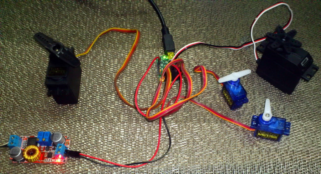
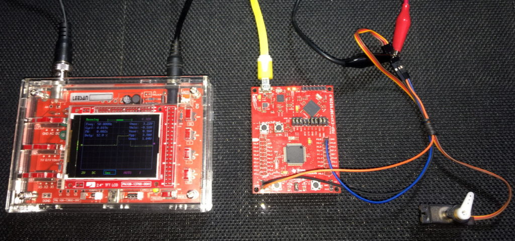
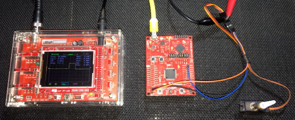
Hardware Setup
Explanation
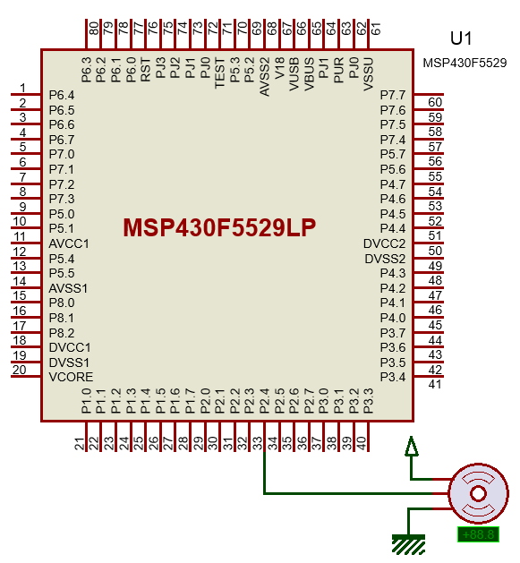
As mentioned, the goal of this demo is to drive a regular servo motor using a single PWM pin of MSP430F5529. Firstly, it must be noted that PWM or Capture-Compare function is a secondary function of GPIO pins. Thus, to use a PWM pin, it must be declared as Output Peripheral Module Function pin.
GPIO_setAsPeripheralModuleFunctionOutputPin(GPIO_PORT_P2, GPIO_PIN4);
Typical servos have a timing as shown below:
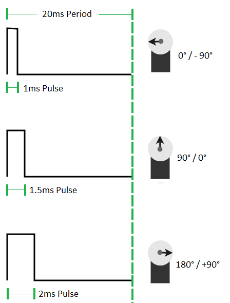
Note that every pulse has a period of 20ms. However, the high time varies from 5 – 10%, i.e. the duty cycle of the PWM should be between 5 – 10% in order to rotate the servo.
This time TA2 is used. We could have used Timer B as it is better suited for PWM. This won’t matter much though for this example.
void timer_T2A3_init(void)
{
    Timer_A_outputPWMParam outputPWMParam = {0};

    outputPWMParam.clockSource = TIMER_A_CLOCKSOURCE_SMCLK;
    outputPWMParam.clockSourceDivider = TIMER_A_CLOCKSOURCE_DIVIDER_2;
    outputPWMParam.timerPeriod = 20000;
    outputPWMParam.compareRegister = TIMER_A_CAPTURECOMPARE_REGISTER_1;
    outputPWMParam.compareOutputMode = TIMER_A_OUTPUTMODE_RESET_SET;
    outputPWMParam.dutyCycle = 0;

    Timer_A_outputPWM(TIMER_A2_BASE, &outputPWMParam);

    Timer_A_setCompareValue(TIMER_A2_BASE,TIMER_A_CAPTURECOMPARE_REGISTER_1, 1000);
}
SMCLK is again used to clock the timer but this time it is scaled by a factor of 2. SMCLK will thus have a frequency of 2MHz as it is feed with 4MHz XT2_CLK.
UCS_initClockSignal(UCS_SMCLK, UCS_XT2CLK_SELECT, UCS_CLOCK_DIVIDER_2);
Inside the timer, this incoming clock signal is further divided by 2 and so the timer will tick at every 1µs. Like up mode, the top value or max PWM duty cycle is set to 20000. This means that the period of the PWM will be 20000 µs or 20 ms. Initially, the duty cycle is set to 0ms and the output mode is set to reset-set mode. Different output modes of MSP430’s PWM are shown below.
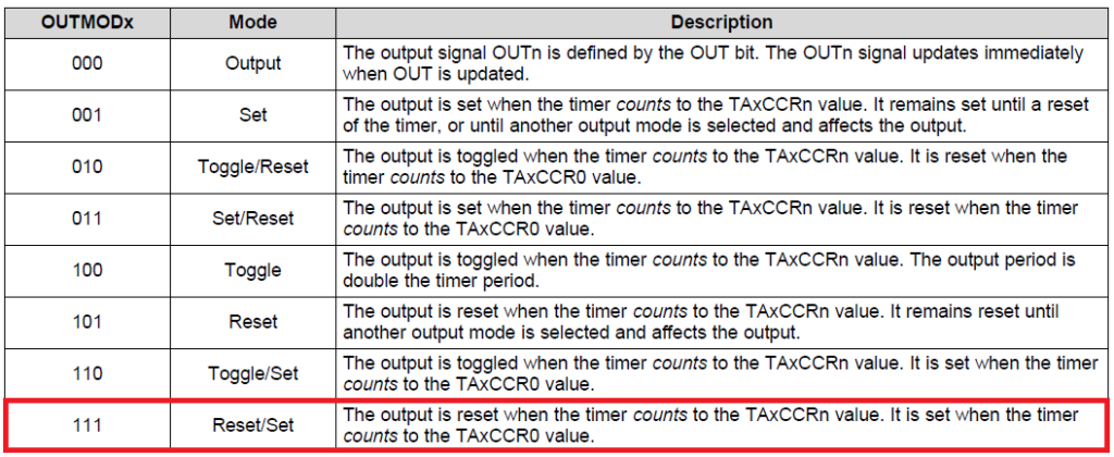
After setting the PWM parameters, the timer and its PWM are started. Initially the pulse high time is set to 1 ms, i.e. the servo will at 0° (-90°) position. We want the servo to rotate back and forth, i.e. from 0° (-90°) to 180° (+90°). To do this, we have to increase and decrease the pulse high time in the main loop.
if((r  0) && (dir == DEC))
{
    r--;
}
if((r == 0) && (dir == DEC))
{
   dir = INC;
}
Timer_A_setCompareValue(TIMER_A2_BASE, TIMER_A_CAPTURECOMPARE_REGISTER_1, (1000 + r));

delay_ms(2);
The line below is responsible of duty cycle variation:
Timer_A_setCompareValue(TIMER_A2_BASE, TIMER_A_CAPTURECOMPARE_REGISTER_1, (1000 + r));
It states which timer it is, which channel it is and the duty cycle of that channel.
Demo
|
|
Hello, dear sir Shawon Shahryiar, could you send me the GRACE program by email? I can’t find it anywhere on the Internet. Thank you very much and all the best.
https://www.dropbox.com/scl/fi/6jgmxuuwl9dw2zo9mpuwm/grace_setup_2.2.0.00006.rar?rlkey=gm20hy3odiuyajjow2pas3iz0&st=hhfakdjt&dl=0
Hello, what software are you using for the Hardware setup images and does it support simulation for the MSP430F5529
I used Proteus VSM for drawing schematics but it doesn’t support simulation.
Hi,
Im interfacing MSP430F5529 with MAX17055 fuel guage. while reading 16 bit value, the first byte im receiving is 0. so while reading multiple registers continuously the data exchange is happening, but im getting the correct data. Can anyone suggest me what will be the issue? why im getting 0 in first byte?
read16_bit data code:
uint16_t value = 0;
USCI_B_I2C_setslaveaddress(USCI_B1_BASE, slave_address);
USCI_B_I2C_setmode(USCI_B1_BASE, USCI_B_I2C_TRANSMIT_MODE);
USCI_B_I2C_masterSendStart(USCI_B1_BASE);
while (!USCI_B_I2C_masterSendStart(USCI_B1_BASE));
USCI_B_I2C_mastterSendSingleByte(USCI_B1_BASE, reg_address);
USCI_B_I2C_setslaveaddress(USCI_B1_BASE, slave_address);
USCI_B_I2C_setmode(USCI_B1_BASE, USCI_B_I2C_TRANSMIT_MODE);
USCI_B_I2C_masterReceiveMultiByteStart(USCI_B1_BASE);
uint8_t lb = USCI_B_I2C_masterReceiveMultiByteNext(USCI_B1_BASE);
uint8_t hb = USCI_B_I2C_masterReceiveMultiByteFinish(USCI_B1_BASE);
while (USCI_B_I2C_isBusBusy(USCI_B_BASE));
value = lb << 8;
value |= hb;
return value;
In code, after sending reg address, it will be recieve mode. its a type mistake
Hi, im trying to send the command from the terminal view. i can able to send the command and tried to blink p1.0 led in msp430f5529 controller, its working fine. And im using led driver IS31FL3236A interfaced with msp430f5529 controller, i can able to interface im getting the expected output.
now i need to send the command from seriak monitor based on that command i2c communication need to start. both communication are working fine, when it runs separately. its not working when i tried to combine.
any one had any idea, why it is happening or what will be the issue?
It could be due to:
1. conflicts in clock settings
2. hardware conflict like pin mapping
3. code is getting stuck or waiting for one communication line to finish
4. use of polling method instead of interrupt-driven coding
Hi, thank you for the respose.
Do I need to use different clock initialization for I2C and UART communication? if YES, can you explain how to do that?
I mean check which clock has been set for UART and I2C…. Is it SMCLK, MCLK, etc and is it tuned to right frequency required by the respective hardware?
Is there any example on how to implement polling method in uart?
Why go for polling method when it is a blocking method of coding? It is better to use interrupts instead at least for UART receive.
yes!! currently in my code, only for uart im using interrupts to recieve command from serial monitor. Im not using interrupt for I2C communication.
so the issue is must be in clock initialization. right?
For UART, im using USCI_A1_BASE. and for I2C, im using USCI_B1_BASE.
And another thing i need to ask is, in uart when i tried blink led(p1.0) in msp430f5529 by passing command. here, without clock I’m getting output. how it is possible?
And for both i2c and uart i gave SMCLK with 1Mhz
I am surprised and happy to find this tutorial on the F5529 as TI makes a lot of different devices.
Thank you very much for putting in the extra knowledge in each segment, made reading worthwhile.
Good Work!
lovely tutorial but to be honest I don’t think I’d be investing my time on this board to start with it’s not cheap and readily available as the stm32 boards can you please do more tutorials on stm32 board’s and the stc micros thanks
Hello, I try to program MSP430FR6047 but i get error “the debug interface to the device has been secured”. when flashing using uniflash and when program using CCS this happen. can you help me to solve this problem
You can try “On connect, erase user code and unlock the device” option.
Pingback: Tinkering TI MSP430F5529 – gStore
Hello
I am doing project of msp430g2553 interface(using i2c communication) with temp 100(temperature sensor) and try to read the temperature in dispaly(16*2) but didn’t get the out put (using code composer studio) can u share me any example code for this project
Thank you sir,
Which sensor? Did you use pullup resistors for SDA-SCL pins?
Where is lcd_print.h?
All files and docs are here:
https://libstock.mikroe.com/projects/view/3233/tinkering-ti-msp430f5529
You want the truth? TI makes and sell “underpowered micros”, you know? Low everything, not only the power but also peripherals. So the price is not justified.
Otherwise, if I’ll move there, I’ll introduce them to my small hobby projects – there are still some advantages.
I may even make a visual configuration tool of my own for them…
Yeah the prices of TI products are higher than other manufacturers but I don’t think the hardware peripherals are inferior.
Not inferior but in not enough numbers compared to STM32.
True