Tinkering TI MSP430F5529

|
|
Timer Input Capture Mode – TA0
Just like PWM, timer input capture is another important feature of a timer. This is an input-side feature unlike PWM. Input capture is needed for measurement of pulse widths, frequency and time period of an incoming waveform.
Code Example
#include "driverlib.h"
#include "delay.h"
#include "lcd.h"
#include "lcd_print.h"

unsigned int pulse_ticks = 0;
unsigned int start_time = 0;
unsigned int end_time = 0;

void clock_init(void);
void GPIO_init(void);
void timer_T0A5_init(void);
void timer_T2A3_init(void);

#pragma vector=TIMER0_A1_VECTOR
__interrupt void TIMER0_A1_ISR(void)
{
  switch(__even_in_range(TA0IV, 10))
  {
       case 0x00: break;             // None
       case 0x02:                    // CCR1 IFG
       {
           end_time = Timer_A_getCaptureCompareCount(TIMER_A0_BASE,
                                                     TIMER_A_CAPTURECOMPARE_REGISTER_1);

           pulse_ticks = (end_time - start_time);

           start_time = end_time;

           Timer_A_clearCaptureCompareInterrupt(TIMER_A0_BASE,
                                                TIMER_A_CAPTURECOMPARE_REGISTER_1);

           break;
       }
       case 0x04: break;             // CCR2 IFG
       case 0x06: break;             // CCR3 IFG
       case 0x08: break;             // CCR4 IFG
       case 0x0A: break;             // CCR5 IFG
       case 0x0C: break;             // CCR6 IFG
       case 0x0E:                    // TA0IFG
       {
           GPIO_toggleOutputOnPin(GPIO_PORT_P1,
                                  GPIO_PIN0);

           break;
       }
       default:   _never_executed();
  }
}

void main(void)
{
    unsigned char i = 0;
    unsigned char settings_changed = false;
    unsigned long timer_clock_frequency = 0;

    WDT_A_hold(WDT_A_BASE);

    clock_init();
    GPIO_init();
    timer_T0A5_init();
    timer_T2A3_init();

    LCD_init();
    LCD_clear_home();

    LCD_goto(0, 0);
    LCD_putstr("PWM./Hz:");

    LCD_goto(0, 1);
    LCD_putstr("Cap./Hz:");

    timer_clock_frequency = UCS_getSMCLK();

    while(true)
    {

        if(GPIO_getInputPinValue(GPIO_PORT_P2,
                                 GPIO_PIN1) == false)
        {
            while(GPIO_getInputPinValue(GPIO_PORT_P2,
                                        GPIO_PIN1) == false);

            i++;

            GPIO_setOutputHighOnPin(GPIO_PORT_P4,
                                    GPIO_PIN7);

            delay_ms(100);

            GPIO_setOutputLowOnPin(GPIO_PORT_P4,
                                   GPIO_PIN7);

            if(i > 5)
            {
                i = 0;
            }

            settings_changed = false;

        }

        switch(settings_changed)
        {
            case true:
            {
                print_I(8, 1, (timer_clock_frequency / pulse_ticks));
                delay_ms(100);
                break;
            }

            default:
            {
                switch(i)
                {
                    case 1:
                    {
                        LCD_goto(9, 0);
                        LCD_putstr("200  ");

                        Timer_A_outputPWMParam outputPWMParam = {0};

                        outputPWMParam.clockSource = TIMER_A_CLOCKSOURCE_SMCLK;
                        outputPWMParam.clockSourceDivider = TIMER_A_CLOCKSOURCE_DIVIDER_4;
                        outputPWMParam.timerPeriod = 5000;
                        outputPWMParam.compareRegister = TIMER_A_CAPTURECOMPARE_REGISTER_1;
                        outputPWMParam.compareOutputMode = TIMER_A_OUTPUTMODE_RESET_SET;
                        outputPWMParam.dutyCycle = 0;

                        Timer_A_outputPWM(TIMER_A2_BASE,
                                          &outputPWMParam);

                        Timer_A_setCompareValue(TIMER_A2_BASE,
                                                TIMER_A_CAPTURECOMPARE_REGISTER_1,
                                                2000);

                        break;
                    }

                    case 2:
                    {
                        LCD_goto(9, 0);
                        LCD_putstr("125  ");

                        Timer_A_outputPWMParam outputPWMParam = {0};

                        outputPWMParam.clockSource = TIMER_A_CLOCKSOURCE_SMCLK;
                        outputPWMParam.clockSourceDivider = TIMER_A_CLOCKSOURCE_DIVIDER_4;
                        outputPWMParam.timerPeriod = 8000;
                        outputPWMParam.compareRegister = TIMER_A_CAPTURECOMPARE_REGISTER_1;
                        outputPWMParam.compareOutputMode = TIMER_A_OUTPUTMODE_RESET_SET;
                        outputPWMParam.dutyCycle = 0;

                        Timer_A_outputPWM(TIMER_A2_BASE,
                                          &outputPWMParam);

                        Timer_A_setCompareValue(TIMER_A2_BASE,
                                                TIMER_A_CAPTURECOMPARE_REGISTER_1,
                                                4000);

                        break;
                    }

                    case 3:
                    {
                        LCD_goto(9, 0);
                        LCD_putstr("1000 ");

                        Timer_A_outputPWMParam outputPWMParam = {0};

                        outputPWMParam.clockSource = TIMER_A_CLOCKSOURCE_SMCLK;
                        outputPWMParam.clockSourceDivider = TIMER_A_CLOCKSOURCE_DIVIDER_4;
                        outputPWMParam.timerPeriod = 1000;
                        outputPWMParam.compareRegister = TIMER_A_CAPTURECOMPARE_REGISTER_1;
                        outputPWMParam.compareOutputMode = TIMER_A_OUTPUTMODE_RESET_SET;
                        outputPWMParam.dutyCycle = 0;

                        Timer_A_outputPWM(TIMER_A2_BASE,
                                          &outputPWMParam);

                        Timer_A_setCompareValue(TIMER_A2_BASE,
                                                TIMER_A_CAPTURECOMPARE_REGISTER_1,
                                                600);

                        break;
                    }

                    case 4:
                    {
                        LCD_goto(9, 0);
                        LCD_putstr("8000 ");

                        Timer_A_outputPWMParam outputPWMParam = {0};

                        outputPWMParam.clockSource = TIMER_A_CLOCKSOURCE_SMCLK;
                        outputPWMParam.clockSourceDivider = TIMER_A_CLOCKSOURCE_DIVIDER_4;
                        outputPWMParam.timerPeriod = 125;
                        outputPWMParam.compareRegister = TIMER_A_CAPTURECOMPARE_REGISTER_1;
                        outputPWMParam.compareOutputMode = TIMER_A_OUTPUTMODE_RESET_SET;
                        outputPWMParam.dutyCycle = 0;

                        Timer_A_outputPWM(TIMER_A2_BASE,
                                          &outputPWMParam);

                        Timer_A_setCompareValue(TIMER_A2_BASE,
                                                TIMER_A_CAPTURECOMPARE_REGISTER_1,
                                                60);

                        break;
                    }

                    case 5:
                    {
                        LCD_goto(9, 0);
                        LCD_putstr("2000 ");

                        Timer_A_outputPWMParam outputPWMParam = {0};

                        outputPWMParam.clockSource = TIMER_A_CLOCKSOURCE_SMCLK;
                        outputPWMParam.clockSourceDivider = TIMER_A_CLOCKSOURCE_DIVIDER_4;
                        outputPWMParam.timerPeriod = 500;
                        outputPWMParam.compareRegister = TIMER_A_CAPTURECOMPARE_REGISTER_1;
                        outputPWMParam.compareOutputMode = TIMER_A_OUTPUTMODE_RESET_SET;
                        outputPWMParam.dutyCycle = 0;

                        Timer_A_outputPWM(TIMER_A2_BASE,
                                          &outputPWMParam);

                        Timer_A_setCompareValue(TIMER_A2_BASE,
                                                TIMER_A_CAPTURECOMPARE_REGISTER_1,
                                                250);

                        break;
                    }

                    default:
                    {

                        LCD_goto(9, 0);
                        LCD_putstr("333.3");

                        Timer_A_outputPWMParam outputPWMParam = {0};

                        outputPWMParam.clockSource = TIMER_A_CLOCKSOURCE_SMCLK;
                        outputPWMParam.clockSourceDivider = TIMER_A_CLOCKSOURCE_DIVIDER_4;
                        outputPWMParam.timerPeriod = 3000;
                        outputPWMParam.compareRegister = TIMER_A_CAPTURECOMPARE_REGISTER_1;
                        outputPWMParam.compareOutputMode = TIMER_A_OUTPUTMODE_RESET_SET;
                        outputPWMParam.dutyCycle = 0;

                        Timer_A_outputPWM(TIMER_A2_BASE,
                                          &outputPWMParam);

                        Timer_A_setCompareValue(TIMER_A2_BASE,
                                                TIMER_A_CAPTURECOMPARE_REGISTER_1,
                                                1500);

                        break;
                    }

                }

                settings_changed = true;

                break;
            }
        }
    };
}

void clock_init(void)
{
    PMM_setVCore(PMM_CORE_LEVEL_3);

    GPIO_setAsPeripheralModuleFunctionInputPin(GPIO_PORT_P5,
                                               (GPIO_PIN4 | GPIO_PIN2));

    GPIO_setAsPeripheralModuleFunctionOutputPin(GPIO_PORT_P5,
                                                (GPIO_PIN5 | GPIO_PIN3));

    UCS_setExternalClockSource(XT1_FREQ,
                               XT2_FREQ);

    UCS_turnOnXT2(UCS_XT2_DRIVE_4MHZ_8MHZ);

    UCS_turnOnLFXT1(UCS_XT1_DRIVE_0,
                    UCS_XCAP_3);

    UCS_initClockSignal(UCS_MCLK,
                        UCS_XT2CLK_SELECT,
                        UCS_CLOCK_DIVIDER_1);

    UCS_initClockSignal(UCS_SMCLK,
                        UCS_XT2CLK_SELECT,
                        UCS_CLOCK_DIVIDER_1);

    UCS_initClockSignal(UCS_ACLK,
                        UCS_XT1CLK_SELECT,
                        UCS_CLOCK_DIVIDER_1);
}

void GPIO_init(void)
{
    GPIO_setAsInputPinWithPullUpResistor(GPIO_PORT_P2,
                                         GPIO_PIN1);

    GPIO_setAsOutputPin(GPIO_PORT_P1,
                        GPIO_PIN0);

    GPIO_setDriveStrength(GPIO_PORT_P1,
                          GPIO_PIN0,
                          GPIO_FULL_OUTPUT_DRIVE_STRENGTH);

    GPIO_setAsOutputPin(GPIO_PORT_P4,
                        GPIO_PIN7);

    GPIO_setDriveStrength(GPIO_PORT_P4,
                          GPIO_PIN7,
                          GPIO_FULL_OUTPUT_DRIVE_STRENGTH);

    GPIO_setAsPeripheralModuleFunctionInputPin(GPIO_PORT_P1,
                                               GPIO_PIN2);

    GPIO_setAsPeripheralModuleFunctionOutputPin(GPIO_PORT_P2,
                                                GPIO_PIN4);
}

void timer_T0A5_init(void)
{
    Timer_A_initCaptureModeParam CaptureModeParam = {0};
    Timer_A_initContinuousModeParam ContinuousModeParam = {0};

    Timer_A_stop(TIMER_A0_BASE);
    Timer_A_clearTimerInterrupt(TIMER_A0_BASE);

    ContinuousModeParam.clockSource = TIMER_A_CLOCKSOURCE_SMCLK;
    ContinuousModeParam.clockSourceDivider = TIMER_A_CLOCKSOURCE_DIVIDER_1;
    ContinuousModeParam.timerInterruptEnable_TAIE = TIMER_A_TAIE_INTERRUPT_ENABLE;
    ContinuousModeParam.timerClear = TIMER_A_SKIP_CLEAR;
    ContinuousModeParam.startTimer = true;

    CaptureModeParam.captureRegister = TIMER_A_CAPTURECOMPARE_REGISTER_1;
    CaptureModeParam.captureMode = TIMER_A_CAPTUREMODE_RISING_EDGE;
    CaptureModeParam.captureInputSelect = TIMER_A_CAPTURE_INPUTSELECT_CCIxA;
    CaptureModeParam.synchronizeCaptureSource = TIMER_A_CAPTURE_ASYNCHRONOUS;
    CaptureModeParam.captureInterruptEnable = TIMER_A_CAPTURECOMPARE_INTERRUPT_ENABLE;

    Timer_A_initContinuousMode(TIMER_A0_BASE,
                               &ContinuousModeParam);

    Timer_A_initCaptureMode(TIMER_A0_BASE,
                            &CaptureModeParam);

    __enable_interrupt();
}

void timer_T2A3_init(void)
{
    Timer_A_outputPWMParam outputPWMParam = {0};

    outputPWMParam.clockSource = TIMER_A_CLOCKSOURCE_SMCLK;
    outputPWMParam.clockSourceDivider = TIMER_A_CLOCKSOURCE_DIVIDER_4;
    outputPWMParam.timerPeriod = 2000;
    outputPWMParam.compareRegister = TIMER_A_CAPTURECOMPARE_REGISTER_1;
    outputPWMParam.compareOutputMode = TIMER_A_OUTPUTMODE_RESET_SET;
    outputPWMParam.dutyCycle = 0;

    Timer_A_outputPWM(TIMER_A2_BASE,
                      &outputPWMParam);

    Timer_A_setCompareValue(TIMER_A2_BASE,
                            TIMER_A_CAPTURECOMPARE_REGISTER_1,
                            1000);
}
Hardware Setup
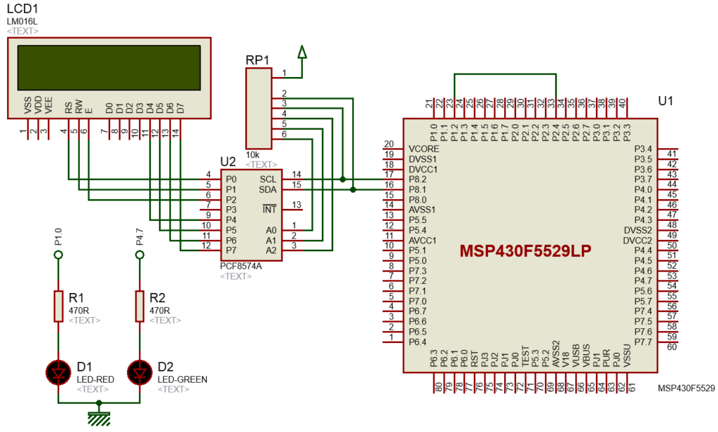
Explanation
In this example, two timers are used. One is set to provide variable frequency PWM while the other is set to measure PWM frequency.
First, let’s see how the PWM is configured. Timer TA2 is used to provide PWM output.
void clock_init(void)
{
....
    UCS_initClockSignal(UCS_SMCLK, UCS_XT2CLK_SELECT, UCS_CLOCK_DIVIDER_1);
....
}


void GPIO_init(void)
{
....
    GPIO_setAsPeripheralModuleFunctionOutputPin(GPIO_PORT_P2, GPIO_PIN4);
}


void timer_T2A3_init(void)
{
    Timer_A_outputPWMParam outputPWMParam = {0};

    outputPWMParam.clockSource = TIMER_A_CLOCKSOURCE_SMCLK;
    outputPWMParam.clockSourceDivider = TIMER_A_CLOCKSOURCE_DIVIDER_4;
    outputPWMParam.timerPeriod = 2000;
    outputPWMParam.compareRegister = TIMER_A_CAPTURECOMPARE_REGISTER_1;
    outputPWMParam.compareOutputMode = TIMER_A_OUTPUTMODE_RESET_SET;
    outputPWMParam.dutyCycle = 0;

    Timer_A_outputPWM(TIMER_A2_BASE,
                      &outputPWMParam);

    Timer_A_setCompareValue(TIMER_A2_BASE,
                            TIMER_A_CAPTURECOMPARE_REGISTER_1,
                            1000);
}
One CC channel of timer T2A3 is used to generate a PWM output of 500Hz with these settings. I believe, by now, the code is not difficult to understand.
On P2.1 button press, the time period and duty cycle of this timer are altered and square waves of different frequencies are generated.
Now let’s see how the capture timer is setup. Capture hardware is made with timer TA0. CC channel 1 is used and therefore P1.2’s secondary function is enabled.
void clock_init(void)
{
....
    UCS_initClockSignal(UCS_SMCLK, UCS_XT2CLK_SELECT, UCS_CLOCK_DIVIDER_1);
....
}

void GPIO_init(void)
{
....
    GPIO_setAsPeripheralModuleFunctionInputPin(GPIO_PORT_P1, GPIO_PIN2);
....
}


void timer_T0A5_init(void)
{
    Timer_A_initCaptureModeParam CaptureModeParam = {0};
    Timer_A_initContinuousModeParam ContinuousModeParam = {0};

    Timer_A_stop(TIMER_A0_BASE);
    Timer_A_clearTimerInterrupt(TIMER_A0_BASE);

    ContinuousModeParam.clockSource = TIMER_A_CLOCKSOURCE_SMCLK;
    ContinuousModeParam.clockSourceDivider = TIMER_A_CLOCKSOURCE_DIVIDER_1;
    ContinuousModeParam.timerInterruptEnable_TAIE = TIMER_A_TAIE_INTERRUPT_ENABLE;
    ContinuousModeParam.timerClear = TIMER_A_SKIP_CLEAR;
    ContinuousModeParam.startTimer = true;

    CaptureModeParam.captureRegister = TIMER_A_CAPTURECOMPARE_REGISTER_1;
    CaptureModeParam.captureMode = TIMER_A_CAPTUREMODE_RISING_EDGE;
    CaptureModeParam.captureInputSelect = TIMER_A_CAPTURE_INPUTSELECT_CCIxA;
    CaptureModeParam.synchronizeCaptureSource = TIMER_A_CAPTURE_ASYNCHRONOUS;
    CaptureModeParam.captureInterruptEnable = TIMER_A_CAPTURECOMPARE_INTERRUPT_ENABLE;

    Timer_A_initContinuousMode(TIMER_A0_BASE, &ContinuousModeParam);

    Timer_A_initCaptureMode(TIMER_A0_BASE, &CaptureModeParam);

    __enable_interrupt();
}
Capture hardware consists of two parts – CC input capture and continuous mode timer.
Firstly, the continuous mode timer is setup. This timer is fed with 4MHz SMCLK. It ticks at every 250ns and approximately overflows every 16ms.
Secondly, the capture part is setup using CC channel 1. It is set to look for rising edges of incoming waveform.
In the interrupt, respective flags are checked. Note both flags are under same interrupt vector. When timer overflow occurs, P1.0 LED is only toggled. However, the interesting part happens inside the CCR1 flag. It is at this stage, time period of capture waveform is captured and calculated.
#pragma vector=TIMER0_A1_VECTOR
__interrupt void TIMER0_A1_ISR(void)
{
  switch(__even_in_range(TA0IV, 10))
  {
       case 0x00: break;             // None
       case 0x02:                    // CCR1 IFG
       {
           end_time = Timer_A_getCaptureCompareCount(TIMER_A0_BASE,                                           TIMER_A_CAPTURECOMPARE_REGISTER_1);

           pulse_ticks = (end_time - start_time);

           start_time = end_time;

           Timer_A_clearCaptureCompareInterrupt(TIMER_A0_BASE,                                                TIMER_A_CAPTURECOMPARE_REGISTER_1);

           break;
       }
       case 0x04: break;             // CCR2 IFG
       case 0x06: break;             // CCR3 IFG
       case 0x08: break;             // CCR4 IFG
       case 0x0A: break;             // CCR5 IFG
       case 0x0C: break;             // CCR6 IFG
       case 0x0E:                    // TA0IFG
       {
           GPIO_toggleOutputOnPin(GPIO_PORT_P1, GPIO_PIN0);

           break;
       }
       default:   _never_executed();
  }
}
When a rising-edge is detected, timer’s current count is immediately stored. When another rising-edge is detected, the timer count of that instance is also stored. Subtracting these two counts results in a count difference. Since we know timer’s tick period, we can use the count difference to compute period/frequency of the incoming waveform.
SMCLK’s frequency is the timer’s operating speed and it is found out by the code as shown below:
timer_clock_frequency = UCS_getSMCLK();
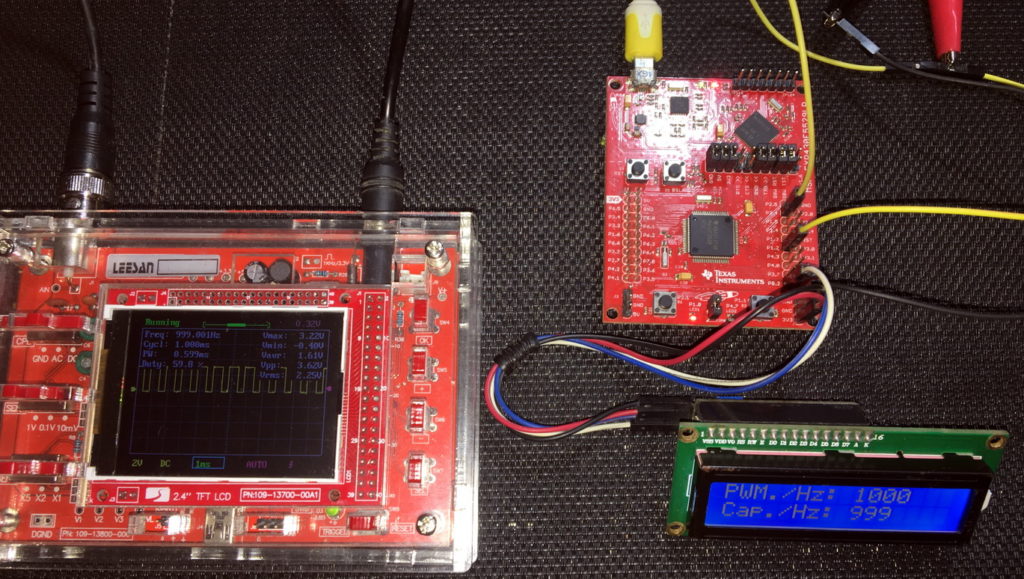
Dividing timer clock frequency (4 MHz) with time count differences, i.e. pulse_ticks, gives us the frequency of capture waveform.
print_I(8, 1, (timer_clock_frequency / pulse_ticks));
delay_ms(100);
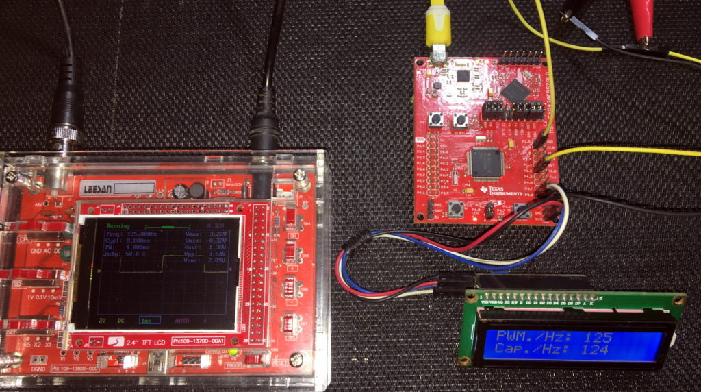
The limitation of this code is inaccuracy of measurement at high frequencies and that’s because at high frequencies, capture resolution decreases. To capture high frequencies, we can use faster clocks or more sampling.
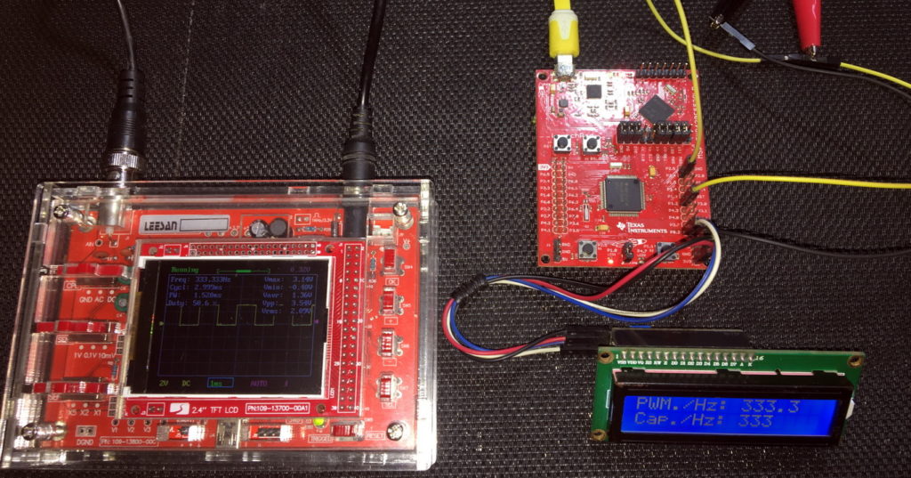
Demo
|
|
Hello, dear sir Shawon Shahryiar, could you send me the GRACE program by email? I can’t find it anywhere on the Internet. Thank you very much and all the best.
https://www.dropbox.com/scl/fi/6jgmxuuwl9dw2zo9mpuwm/grace_setup_2.2.0.00006.rar?rlkey=gm20hy3odiuyajjow2pas3iz0&st=hhfakdjt&dl=0
Hello, what software are you using for the Hardware setup images and does it support simulation for the MSP430F5529
I used Proteus VSM for drawing schematics but it doesn’t support simulation.
Hi,
Im interfacing MSP430F5529 with MAX17055 fuel guage. while reading 16 bit value, the first byte im receiving is 0. so while reading multiple registers continuously the data exchange is happening, but im getting the correct data. Can anyone suggest me what will be the issue? why im getting 0 in first byte?
read16_bit data code:
uint16_t value = 0;
USCI_B_I2C_setslaveaddress(USCI_B1_BASE, slave_address);
USCI_B_I2C_setmode(USCI_B1_BASE, USCI_B_I2C_TRANSMIT_MODE);
USCI_B_I2C_masterSendStart(USCI_B1_BASE);
while (!USCI_B_I2C_masterSendStart(USCI_B1_BASE));
USCI_B_I2C_mastterSendSingleByte(USCI_B1_BASE, reg_address);
USCI_B_I2C_setslaveaddress(USCI_B1_BASE, slave_address);
USCI_B_I2C_setmode(USCI_B1_BASE, USCI_B_I2C_TRANSMIT_MODE);
USCI_B_I2C_masterReceiveMultiByteStart(USCI_B1_BASE);
uint8_t lb = USCI_B_I2C_masterReceiveMultiByteNext(USCI_B1_BASE);
uint8_t hb = USCI_B_I2C_masterReceiveMultiByteFinish(USCI_B1_BASE);
while (USCI_B_I2C_isBusBusy(USCI_B_BASE));
value = lb << 8;
value |= hb;
return value;
In code, after sending reg address, it will be recieve mode. its a type mistake
Hi, im trying to send the command from the terminal view. i can able to send the command and tried to blink p1.0 led in msp430f5529 controller, its working fine. And im using led driver IS31FL3236A interfaced with msp430f5529 controller, i can able to interface im getting the expected output.
now i need to send the command from seriak monitor based on that command i2c communication need to start. both communication are working fine, when it runs separately. its not working when i tried to combine.
any one had any idea, why it is happening or what will be the issue?
It could be due to:
1. conflicts in clock settings
2. hardware conflict like pin mapping
3. code is getting stuck or waiting for one communication line to finish
4. use of polling method instead of interrupt-driven coding
Hi, thank you for the respose.
Do I need to use different clock initialization for I2C and UART communication? if YES, can you explain how to do that?
I mean check which clock has been set for UART and I2C…. Is it SMCLK, MCLK, etc and is it tuned to right frequency required by the respective hardware?
Is there any example on how to implement polling method in uart?
Why go for polling method when it is a blocking method of coding? It is better to use interrupts instead at least for UART receive.
yes!! currently in my code, only for uart im using interrupts to recieve command from serial monitor. Im not using interrupt for I2C communication.
so the issue is must be in clock initialization. right?
For UART, im using USCI_A1_BASE. and for I2C, im using USCI_B1_BASE.
And another thing i need to ask is, in uart when i tried blink led(p1.0) in msp430f5529 by passing command. here, without clock I’m getting output. how it is possible?
And for both i2c and uart i gave SMCLK with 1Mhz
I am surprised and happy to find this tutorial on the F5529 as TI makes a lot of different devices.
Thank you very much for putting in the extra knowledge in each segment, made reading worthwhile.
Good Work!
lovely tutorial but to be honest I don’t think I’d be investing my time on this board to start with it’s not cheap and readily available as the stm32 boards can you please do more tutorials on stm32 board’s and the stc micros thanks
Hello, I try to program MSP430FR6047 but i get error “the debug interface to the device has been secured”. when flashing using uniflash and when program using CCS this happen. can you help me to solve this problem
You can try “On connect, erase user code and unlock the device” option.
Pingback: Tinkering TI MSP430F5529 – gStore
Hello
I am doing project of msp430g2553 interface(using i2c communication) with temp 100(temperature sensor) and try to read the temperature in dispaly(16*2) but didn’t get the out put (using code composer studio) can u share me any example code for this project
Thank you sir,
Which sensor? Did you use pullup resistors for SDA-SCL pins?
Where is lcd_print.h?
All files and docs are here:
https://libstock.mikroe.com/projects/view/3233/tinkering-ti-msp430f5529
You want the truth? TI makes and sell “underpowered micros”, you know? Low everything, not only the power but also peripherals. So the price is not justified.
Otherwise, if I’ll move there, I’ll introduce them to my small hobby projects – there are still some advantages.
I may even make a visual configuration tool of my own for them…
Yeah the prices of TI products are higher than other manufacturers but I don’t think the hardware peripherals are inferior.
Not inferior but in not enough numbers compared to STM32.
True