Tinkering TI MSP430F5529

|
|
Unified Clock System – UCS
MSP430F5529 just like other MSP430s have a very sophisticated clock system called Unified Clock System (UCS). This is a modern trend for most microcontrollers. The goal of such sophistications is to allow users to balance between performance and power optimization with minute compromises. Shown below is the block diagram of UCS. Though it may appear complicated, it has two main parts – clocks signals and their sources.
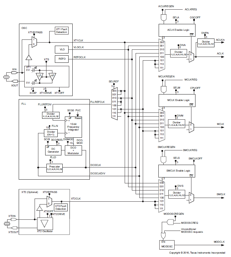
In a MSP430F5529
micro, there are three clock signals or simply clocks that drive internal
hardware peripheral modules and the CPU. These clocks can be feed with
different sources independently and have independent divider/scalars. Different
clocks have different primary uses. These clocks are as follows:
- Master Clock – MCLK
- Used primarily for CPU.
- Usually very fast and usually fastest amongst other clocks.
- Sub-Master Clock – SMCLK
- Used for hardware peripheral modules like timers, ADC, USCI, etc.
- Can be as fast as MCLK.
- Auxiliary Clock – ACLK
- Can be used for hardware peripheral modules specially the low power ones.
- Typically, slower than other clocks and acts as a tertiary clock.
The following clock sources can independently feed the aforementioned clock signals:
- Very Low Oscillator Clock – VLOCLK
- On-chip very low frequency RC oscillator (about 10kHz).
- Not very accurate.
- Intended for idle/sleep modes and timing insensitive tasks.
- Reference Oscillator Clock – REFOCLK
- On-chip reference oscillator (32.768kHz).
- Moderately accurate.
- Digitally Controlled Oscillator – DCO
- Digitally-controlled fast oscillator
source.
- Stabilized Frequency-Locked-Loop (FLL).
- External Oscillator 1 – XT1CLK
- 32.768kHz crystal.
- Useful for driving the RTC module.
- Can be feed with other external crystals or external clock sources from 4 – 32MHz.
- External
Oscillator 2 – XT2CLK
- In a Launchpad board, this is connected to an external onboard 4 MHz crystal.
- Can be feed with crystals or external clock sources from 4 – 32MHz.
All of these sources and clock signals can be applied in a vast number of combinations, allowing us to set, fine tune and run the Digitally Controlled Oscillator (DCO) at an astonishing speed of 25MHz.
Code Example
delay.h
#define XT1_FREQ          32768
#define XT2_FREQ          4000000
#define MCLK_FREQ         25000000

#define XT1_KHZ           (XT1_FREQ / 1000)
#define XT2_KHZ           (XT2_FREQ / 1000)
#define MCLK_KHZ          (MCLK_FREQ / 1000)

#define scale_factor       4

#define MCLK_FLLREF_RATIO (MCLK_KHZ / (XT2_KHZ / scale_factor))

#define CPU_F             ((double)MCLK_FREQ)

#define delay_us(delay) __delay_cycles((long)(CPU_F*(((double)delay)/1000000.0)))
#define delay_ms(delay) __delay_cycles((long)(CPU_F*(((double)delay)/1000.0)))main.c
main.c
#include "driverlib.h"
#include "delay.h"

void indicate(void)
{
    GPIO_setOutputHighOnPin(GPIO_PORT_P4, GPIO_PIN7);

    delay_ms(20);

    GPIO_setOutputLowOnPin(GPIO_PORT_P4, GPIO_PIN7);

    delay_ms(20);
}

void toggle_LED(void)
{
    signed char i = 2;

    while(i > -1)
    {
        GPIO_toggleOutputOnPin(GPIO_PORT_P1, GPIO_PIN0);

        delay_ms(40);
        i--;
    };

    GPIO_setOutputLowOnPin(GPIO_PORT_P1, GPIO_PIN0);
}

void main(void)
{
    WDT_A_hold(WDT_A_BASE);

    GPIO_setAsOutputPin(GPIO_PORT_P1,
                        GPIO_PIN0);

    GPIO_setDriveStrength(GPIO_PORT_P1,
                          GPIO_PIN0,
                          GPIO_FULL_OUTPUT_DRIVE_STRENGTH);

    GPIO_setAsOutputPin(GPIO_PORT_P4,
                        GPIO_PIN7);

    GPIO_setDriveStrength(GPIO_PORT_P4,
                          GPIO_PIN7,
                          GPIO_FULL_OUTPUT_DRIVE_STRENGTH);

    indicate();
    toggle_LED();

    UCS_initClockSignal(UCS_MCLK,
                        UCS_XT2CLK_SELECT,
                        UCS_CLOCK_DIVIDER_1);

    indicate();
    toggle_LED();

    UCS_initClockSignal(UCS_MCLK,
                        UCS_REFOCLK_SELECT,
                        UCS_CLOCK_DIVIDER_1);

    indicate();
    toggle_LED();

    PMM_setVCore(PMM_CORE_LEVEL_3);

    GPIO_setAsPeripheralModuleFunctionInputPin(GPIO_PORT_P5,
                                               (GPIO_PIN4 | GPIO_PIN2));

    GPIO_setAsPeripheralModuleFunctionOutputPin(GPIO_PORT_P5,
                                                (GPIO_PIN5 | GPIO_PIN3));

    UCS_setExternalClockSource(XT1_FREQ,
                               XT2_FREQ);

    UCS_turnOnXT2(UCS_XT2_DRIVE_4MHZ_8MHZ);

    UCS_turnOnLFXT1(UCS_XT1_DRIVE_0,
                    UCS_XCAP_3);

    UCS_initClockSignal(UCS_FLLREF,
                        UCS_XT2CLK_SELECT,
                        UCS_CLOCK_DIVIDER_4);

    UCS_initFLLSettle(MCLK_KHZ,
                      MCLK_FLLREF_RATIO);

    UCS_initClockSignal(UCS_SMCLK,
                        UCS_REFOCLK_SELECT,
                        UCS_CLOCK_DIVIDER_1);

    UCS_initClockSignal(UCS_ACLK,
                        UCS_XT1CLK_SELECT,
                        UCS_CLOCK_DIVIDER_1);

    indicate();

    while (1)
    {
        toggle_LED();
    };
}
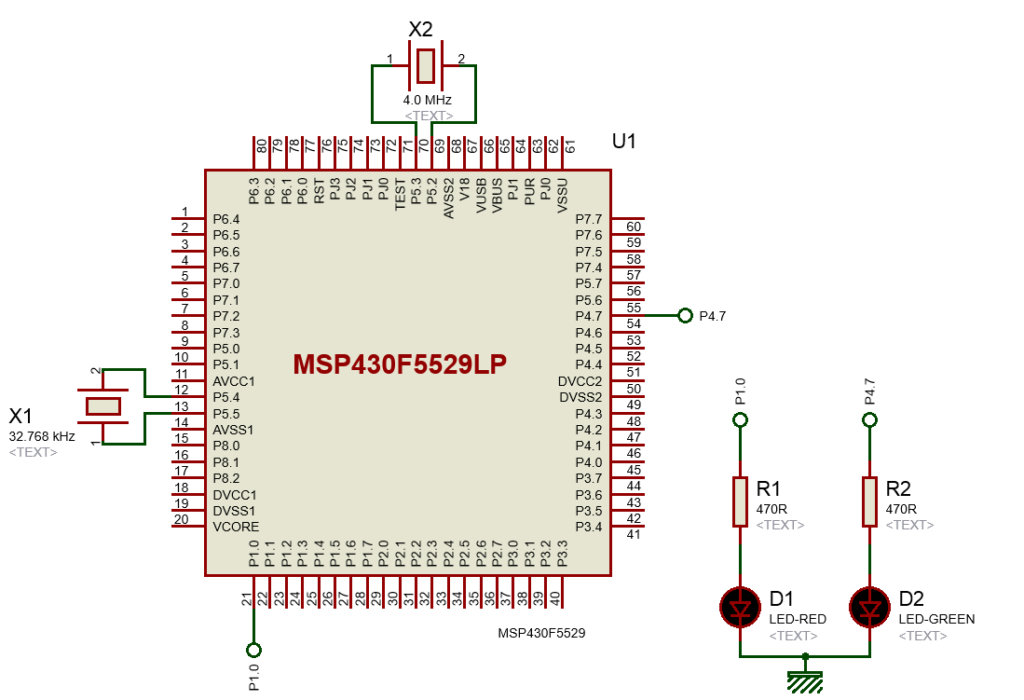
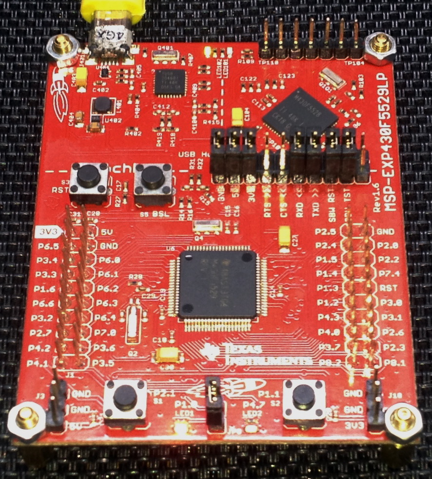
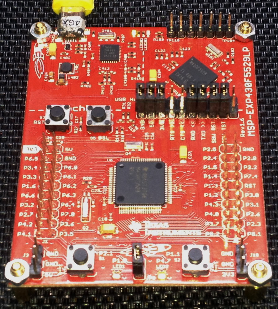
Hardware Setup
Explanation
Unless altered or set by coder, the default clock speeds of the three clocks are as follows:
- MCLK ≈ 1.0 MHz
- SMCLK ≈ 1.0 MHz
- ACLK = 32.768 kHz
However, we don’t want to use these defaults as it is pointless to use so when we have better options. We can alter clock settings and tune the Digitally Controlled Oscillator (DCO) to run at 25MHz which is, by the way, the max clock speed of MSP430F5529 micro.
The demo here demonstrates how clock speed affects LED blinking over the same amount of delay. Different clocks are initiated with different settings and LED blinking is monitored. The on-board green LED (indicate function) indicates a change in clock settings while the on-board red LED (toggle function) is blinked as an indicator of speed. This is possibly the simplest arrangement.
{
    GPIO_setOutputHighOnPin(GPIO_PORT_P4, GPIO_PIN7);
    delay_ms(20);

    GPIO_setOutputLowOnPin(GPIO_PORT_P4, GPIO_PIN7);
    delay_ms(20);
}

void toggle_LED(void)
{
    signed char i = 2;

    while(i > -1)
    {
        GPIO_toggleOutputOnPin(GPIO_PORT_P1, GPIO_PIN0);
        delay_ms(40);
        i--;
    };

    GPIO_setOutputLowOnPin(GPIO_PORT_P1, GPIO_PIN0);
}
At first, no clock settings are applied and so the clocks operate at their respective default speeds. Note that software delays are dependent on MCLK frequency and so LED flashing will differ with different MCLK speeds. Please refer to delay library header file. In the code, the delay amounts are not adjusted with clock speeds.
#define XT1_FREQ          32768
#define XT2_FREQ          4000000
#define MCLK_FREQ         25000000

#define XT1_KHZ           (XT1_FREQ / 1000)
#define XT2_KHZ           (XT2_FREQ / 1000)
#define MCLK_KHZ          (MCLK_FREQ / 1000)

#define scale_factor       4

#define MCLK_FLLREF_RATIO (MCLK_KHZ / (XT2_KHZ / scale_factor))

#define CPU_F             ((double)MCLK_FREQ)

#define delay_us(delay)    __delay_cycles((long)(CPU_F*(((double)delay)/1000000.0)))
#define delay_ms(delay)    __delay_cycles((long)(CPU_F*(((double)delay)/1000.0)))
In the code, you’ll notice that only MCLK is altered for the aforementioned reason.
UCS_initClockSignal(UCS_MCLK, UCS_XT2CLK_SELECT, UCS_CLOCK_DIVIDER_1);
....
UCS_initClockSignal(UCS_MCLK, UCS_REFOCLK_SELECT, UCS_CLOCK_DIVIDER_1);
Up to this point only internal sources have been employed but we do have options for external and high frequency clocks. To use on-board external crystals, we have to initialize their respective pins.
GPIO_setAsPeripheralModuleFunctionInputPin(GPIO_PORT_P5, (GPIO_PIN4 | GPIO_PIN2));

GPIO_setAsPeripheralModuleFunctionOutputPin(GPIO_PORT_P5, (GPIO_PIN5 | GPIO_PIN3));
These pins should be initiated as alternative/secondary function pins. Port Mapping Controller (PMC) does this job in background. If these pins are not initialized properly as such, the crystals may not function at all and we may end up with an inert lifeless microcontroller.
As per onboard crystal placement, keep in mind that
- XT1 = 32.768 kHz
- XT2 = 4.0 MHz
With the pins initialized, we are ready to set the external sources as per their respective frequencies.
UCS_setExternalClockSource(XT1_FREQ, XT2_FREQ);
We can directly use these sources for clocks:
UCS_initClockSignal(UCS_ACLK, UCS_XT1CLK_SELECT, UCS_CLOCK_DIVIDER_1);
We can also use these sources to tune the DCO. To tune the DCO, we must initialize the Frequency Locked Loop (FLL) using either internal or external sources. First, the FLL’s reference clock source is initialized.
UCS_initClockSignal(UCS_FLLREF, UCS_XT2CLK_SELECT, UCS_CLOCK_DIVIDER_4);
After this, the FLL is allowed to stabilize or settle.
UCS_initFLLSettle(MCLK_KHZ, MCLK_FLLREF_RATIO);
The following lines in the delay header file are important because their values alter MCLK frequency.
#define MCLK_KHZ          (MCLK_FREQ / 1000)

#define scale_factor       4

#define MCLK_FLLREF_RATIO (MCLK_KHZ / (XT2_KHZ / scale_factor))
Another thing that is very important to note is the relation between system frequency and core power mode. The graph below shows this relation.
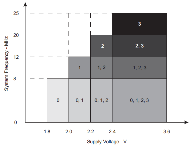
From the graph, we can see that higher the system clock frequency, the higher is the required supply voltage, i.e. core power. By default, the core power mode is 0 and, in this mode, the maximum system clock frequency is 8 MHz. My example code goes to maximum operating frequency of 25 MHz at the ending and so core power mode 3 is applied before setting the FLL.
PMM_setVCore(PMM_CORE_LEVEL_3);
The rest of the clocks (ACLK and SMCLK) are set after setting the MCLK.
Demo
|
|
Hello, what software are you using for the Hardware setup images and does it support simulation for the MSP430F5529
I used Proteus VSM for drawing schematics but it doesn’t support simulation.
Hi,
Im interfacing MSP430F5529 with MAX17055 fuel guage. while reading 16 bit value, the first byte im receiving is 0. so while reading multiple registers continuously the data exchange is happening, but im getting the correct data. Can anyone suggest me what will be the issue? why im getting 0 in first byte?
read16_bit data code:
uint16_t value = 0;
USCI_B_I2C_setslaveaddress(USCI_B1_BASE, slave_address);
USCI_B_I2C_setmode(USCI_B1_BASE, USCI_B_I2C_TRANSMIT_MODE);
USCI_B_I2C_masterSendStart(USCI_B1_BASE);
while (!USCI_B_I2C_masterSendStart(USCI_B1_BASE));
USCI_B_I2C_mastterSendSingleByte(USCI_B1_BASE, reg_address);
USCI_B_I2C_setslaveaddress(USCI_B1_BASE, slave_address);
USCI_B_I2C_setmode(USCI_B1_BASE, USCI_B_I2C_TRANSMIT_MODE);
USCI_B_I2C_masterReceiveMultiByteStart(USCI_B1_BASE);
uint8_t lb = USCI_B_I2C_masterReceiveMultiByteNext(USCI_B1_BASE);
uint8_t hb = USCI_B_I2C_masterReceiveMultiByteFinish(USCI_B1_BASE);
while (USCI_B_I2C_isBusBusy(USCI_B_BASE));
value = lb << 8;
value |= hb;
return value;
In code, after sending reg address, it will be recieve mode. its a type mistake
Hi, im trying to send the command from the terminal view. i can able to send the command and tried to blink p1.0 led in msp430f5529 controller, its working fine. And im using led driver IS31FL3236A interfaced with msp430f5529 controller, i can able to interface im getting the expected output.
now i need to send the command from seriak monitor based on that command i2c communication need to start. both communication are working fine, when it runs separately. its not working when i tried to combine.
any one had any idea, why it is happening or what will be the issue?
It could be due to:
1. conflicts in clock settings
2. hardware conflict like pin mapping
3. code is getting stuck or waiting for one communication line to finish
4. use of polling method instead of interrupt-driven coding
Hi, thank you for the respose.
Do I need to use different clock initialization for I2C and UART communication? if YES, can you explain how to do that?
I mean check which clock has been set for UART and I2C…. Is it SMCLK, MCLK, etc and is it tuned to right frequency required by the respective hardware?
Is there any example on how to implement polling method in uart?
Why go for polling method when it is a blocking method of coding? It is better to use interrupts instead at least for UART receive.
yes!! currently in my code, only for uart im using interrupts to recieve command from serial monitor. Im not using interrupt for I2C communication.
so the issue is must be in clock initialization. right?
For UART, im using USCI_A1_BASE. and for I2C, im using USCI_B1_BASE.
And another thing i need to ask is, in uart when i tried blink led(p1.0) in msp430f5529 by passing command. here, without clock I’m getting output. how it is possible?
And for both i2c and uart i gave SMCLK with 1Mhz
I am surprised and happy to find this tutorial on the F5529 as TI makes a lot of different devices.
Thank you very much for putting in the extra knowledge in each segment, made reading worthwhile.
Good Work!
lovely tutorial but to be honest I don’t think I’d be investing my time on this board to start with it’s not cheap and readily available as the stm32 boards can you please do more tutorials on stm32 board’s and the stc micros thanks
Hello, I try to program MSP430FR6047 but i get error “the debug interface to the device has been secured”. when flashing using uniflash and when program using CCS this happen. can you help me to solve this problem
You can try “On connect, erase user code and unlock the device” option.
Pingback: Tinkering TI MSP430F5529 – gStore
Hello
I am doing project of msp430g2553 interface(using i2c communication) with temp 100(temperature sensor) and try to read the temperature in dispaly(16*2) but didn’t get the out put (using code composer studio) can u share me any example code for this project
Thank you sir,
Which sensor? Did you use pullup resistors for SDA-SCL pins?
Where is lcd_print.h?
All files and docs are here:
https://libstock.mikroe.com/projects/view/3233/tinkering-ti-msp430f5529
You want the truth? TI makes and sell “underpowered micros”, you know? Low everything, not only the power but also peripherals. So the price is not justified.
Otherwise, if I’ll move there, I’ll introduce them to my small hobby projects – there are still some advantages.
I may even make a visual configuration tool of my own for them…
Yeah the prices of TI products are higher than other manufacturers but I don’t think the hardware peripherals are inferior.
Not inferior but in not enough numbers compared to STM32.
True