Tinkering TI MSP430F5529

|
|
USCI – UART
UART/serial communication in MSP430s is achieved using USCI modules. In MSP430F5529, USCI A modules can be used for both SPI and UART.
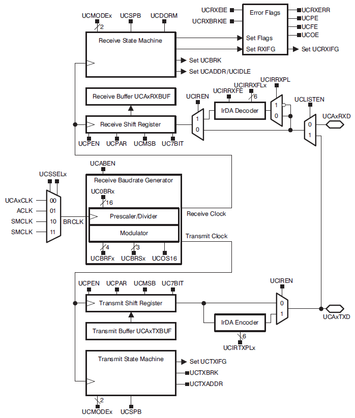
The block diagram of USCI in UART mode is shown above. As can be seen, UART module can be clocked with four clock sources. These clock sources can be fine-tuned for desired baud rates. There are separate buffers and state machines for transmission and reception parts. The UART module can use used for IrDA communication and there are optional internal encoder and decoder for so. Lastly, there are flags for events and errors at various points.
Eltima Soft
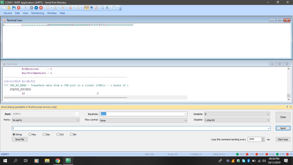
Eltima software is a US-based company that make some useful computer communication software interfaces. Eltima has been kind enough to supply me their Serial Port Monitor.
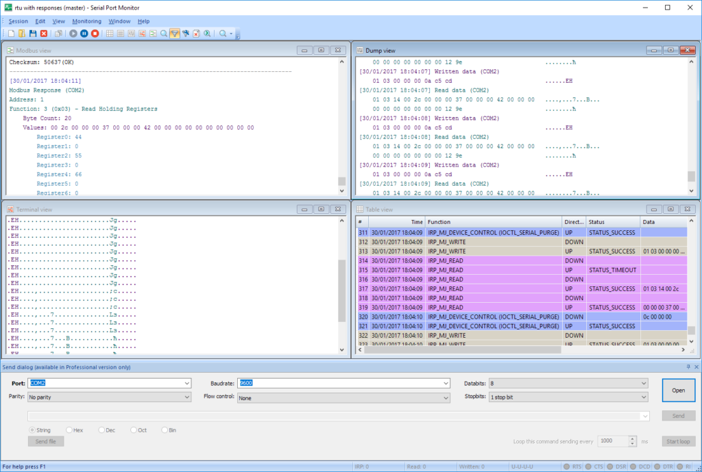
In embedded-system world, we all use some kind of serial port monitor but Eltima’s serial port monitor has the following features that are not usually available in other software:
- COM data logging in real-time and saving for later uses
- Multi-port monitoring in one session
- Five different visualization modes
- Emulation of port
- Sniffing of MODBUS RTU and ASCII data
- Comparison of sessions
- Easy to use user-interface
- Changing of serial port parameters on-the-fly
- Digitally signed drivers
- Advanced filtering
Of the many features, I particularly liked the logging and MOBUS features. I have no other similar software to compare with it. I highly recommend readers to use it and see for themselves.
In this tutorial post, I have exclusively used this software.
Code Example
#include "driverlib.h"
#include "delay.h"
#include "lcd.h"
#include "lcd_print.h"

char RX_Data = 0;
char TX_Data = 0;

void clock_init(void);
void GPIO_init(void);
void USCI_UART_init(void);

#pragma vector = USCI_A1_VECTOR
__interrupt void UART_ISR(void)
{
    switch(__even_in_range(UCA1IV, 4))
    {
        case 0x00:      // None
        {
            break;
        }

        case 0x02:      //Data RX
        {
            RX_Data = USCI_A_UART_receiveData(USCI_A1_BASE);

            GPIO_toggleOutputOnPin(GPIO_PORT_P4,
                                   GPIO_PIN7);

            break;
        }

        case 0x04:      //TX Buffer Empty
        {
            break;
        }
    }
}

void main(void)
{
    WDT_A_hold(WDT_A_BASE);

    clock_init();

    USCI_UART_init();

    GPIO_init();

    LCD_init();
    LCD_clear_home();

    LCD_goto(0, 0);
    LCD_putstr("MSP430 USCI UART");
    LCD_goto(0, 1);
    LCD_putstr("TXD: ");
    LCD_goto(10, 1);
    LCD_putstr("RXD: ");

    while(1)
    {
        TX_Data = RX_Data;

        GPIO_toggleOutputOnPin(GPIO_PORT_P1,
                               GPIO_PIN0);

        USCI_A_UART_transmitData(USCI_A1_BASE,
                                 TX_Data);

        while(USCI_A_UART_getInterruptStatus(USCI_A1_BASE,                                                                                                               USCI_A_UART_TRANSMIT_INTERRUPT_FLAG) == 0);

        LCD_goto(5, 1);
        LCD_putchar(TX_Data);

        LCD_goto(15, 1);
        LCD_putchar(RX_Data);

        delay_ms(900);
    };
}

void clock_init(void)
{
    PMM_setVCore(PMM_CORE_LEVEL_3);

    GPIO_setAsPeripheralModuleFunctionInputPin(GPIO_PORT_P5,
                                               (GPIO_PIN4 | GPIO_PIN2));

    GPIO_setAsPeripheralModuleFunctionOutputPin(GPIO_PORT_P5,
                                                (GPIO_PIN5 | GPIO_PIN3));

    UCS_setExternalClockSource(XT1_FREQ,
                               XT2_FREQ);

    UCS_turnOnXT2(UCS_XT2_DRIVE_4MHZ_8MHZ);

    UCS_turnOnLFXT1(UCS_XT1_DRIVE_3,
                    UCS_XCAP_3);

    UCS_initClockSignal(UCS_FLLREF,
                        UCS_XT2CLK_SELECT,
                        UCS_CLOCK_DIVIDER_4);

    UCS_initFLLSettle(MCLK_KHZ,
                      MCLK_FLLREF_RATIO);

    UCS_initClockSignal(UCS_SMCLK,
                        UCS_XT2CLK_SELECT,
                        UCS_CLOCK_DIVIDER_4);

    UCS_initClockSignal(UCS_ACLK,
                        UCS_XT1CLK_SELECT,
                        UCS_CLOCK_DIVIDER_1);
}

void GPIO_init(void)
{
    GPIO_setAsOutputPin(GPIO_PORT_P1,
                        GPIO_PIN0);

    GPIO_setDriveStrength(GPIO_PORT_P1,
                          GPIO_PIN0,
                          GPIO_FULL_OUTPUT_DRIVE_STRENGTH);

    GPIO_setAsOutputPin(GPIO_PORT_P4,
                        GPIO_PIN7);

    GPIO_setDriveStrength(GPIO_PORT_P4,
                          GPIO_PIN7,
                          GPIO_FULL_OUTPUT_DRIVE_STRENGTH);

    GPIO_setAsPeripheralModuleFunctionInputPin(GPIO_PORT_P4,
                                               GPIO_PIN5);

    GPIO_setAsPeripheralModuleFunctionOutputPin(GPIO_PORT_P4,
                                                GPIO_PIN4);
}

void USCI_UART_init(void)
{
    USCI_A_UART_initParam UART_Param = {0};

    UART_Param.selectClockSource = USCI_A_UART_CLOCKSOURCE_ACLK;
    UART_Param.clockPrescalar = 3;
    UART_Param.firstModReg = 0;
    UART_Param.secondModReg = 3;
    UART_Param.msborLsbFirst = USCI_A_UART_LSB_FIRST;
    UART_Param.parity = USCI_A_UART_NO_PARITY;
    UART_Param.numberofStopBits = USCI_A_UART_ONE_STOP_BIT;
    UART_Param.uartMode = USCI_A_UART_MODE;
    UART_Param.overSampling = USCI_A_UART_LOW_FREQUENCY_BAUDRATE_GENERATION;

    USCI_A_UART_init(USCI_A1_BASE,
                     &UART_Param);

    USCI_A_UART_resetDormant(USCI_A1_BASE);

    USCI_A_UART_enable(USCI_A1_BASE);

    USCI_A_UART_enableInterrupt(USCI_A1_BASE,
                                USCI_A_UART_RECEIVE_INTERRUPT);

    __enable_interrupt();
}
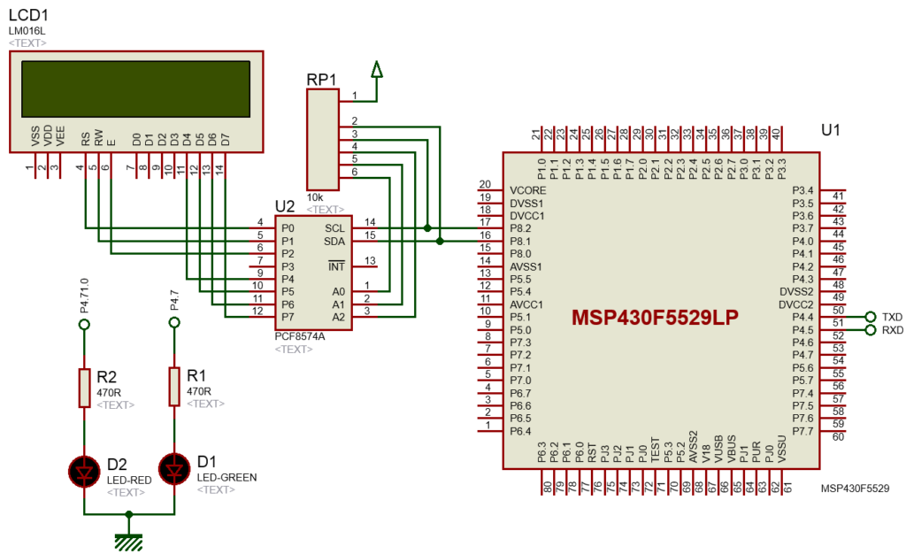
Hardware Setup
Explanation
Firstly, GPIO pins are initialized as secondary function pins.
GPIO_setAsPeripheralModuleFunctionInputPin(GPIO_PORT_P4, GPIO_PIN5);

GPIO_setAsPeripheralModuleFunctionOutputPin(GPIO_PORT_P4, GPIO_PIN4);
The following function initializes USCI A1 module in UART mode.
void USCI_UART_init(void)
{
    USCI_A_UART_initParam UART_Param = {0};

    UART_Param.selectClockSource = USCI_A_UART_CLOCKSOURCE_ACLK;
    UART_Param.clockPrescalar = 3;
    UART_Param.firstModReg = 0;
    UART_Param.secondModReg = 3;
    UART_Param.msborLsbFirst = USCI_A_UART_LSB_FIRST;
    UART_Param.parity = USCI_A_UART_NO_PARITY;
    UART_Param.numberofStopBits = USCI_A_UART_ONE_STOP_BIT;
    UART_Param.uartMode = USCI_A_UART_MODE;
    UART_Param.overSampling = USCI_A_UART_LOW_FREQUENCY_BAUDRATE_GENERATION;

    USCI_A_UART_init(USCI_A1_BASE, &UART_Param);
    USCI_A_UART_resetDormant(USCI_A1_BASE);
    USCI_A_UART_enable(USCI_A1_BASE);
    USCI_A_UART_enableInterrupt(USCI_A1_BASE, USCI_A_UART_RECEIVE_INTERRUPT);
    __enable_interrupt();
}
In serial communication, baud rate selection is very important because two serial communication devices must negotiate under a common data transaction rate or else data is unrecognized or treated as garbage. Since baud rate clock-sensitive, we have to carefully chose clock and prescalar settings and this is reflected in the first setting values – clockPrescalar, firstModReg and secondModReg. Now let’s see how we came to these values. Refer to section 36.3.13 Typical Baud Rates and Errors of MSP430x5xx and MSP430x6xx Family User’s Guide.
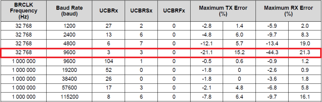
We have used ACLK as the clock source for UART. ACLK happens to be derived from XT1 oscillator and so its frequency is 32.768 kHz.
UCS_initClockSignal(UCS_ACLK, UCS_XT1CLK_SELECT, UCS_CLOCK_DIVIDER_1);
Therefore, to achieve a baud rate of 9600, we have to put the values as shown in the highlighted section of the table above. With these settings the TX-RX errors are high but still we will go with these just to see that even after such high error rates, the serial communication remains smooth and steady.
The rest of the settings describe other properties of our MSP430’s serial port. These include number of stop bits, parity, USCI mode and others.
We will be using reception interrupt and so it is also needed to be enabled.
USCI_A_UART_enableInterrupt(USCI_A1_BASE, USCI_A_UART_RECEIVE_INTERRUPT);
Sending data is very easy. It is just like what we did in SPI examples. We write the data to be sent and wait for the transmit buffer to get empty.
USCI_A_UART_transmitData(USCI_A1_BASE, TX_Data);
while(USCI_A_UART_getInterruptStatus(USCI_A1_BASE,
                                     USCI_A_UART_TRANSMIT_INTERRUPT_FLAG) == 0);
Data is received in the interrupt. It is a very simple process. Once a reception interrupt is triggered, we just have to read the reception buffer. Interrupt flag is automatically cleared.
#pragma vector = USCI_A1_VECTOR
__interrupt void UART_ISR(void)
{
    switch(__even_in_range(UCA1IV, 4))
    {
        case 0x00:      // None
        {
            break;
        }

        case 0x02:      //Data RX
        {
            RX_Data = USCI_A_UART_receiveData(USCI_A1_BASE);

            GPIO_toggleOutputOnPin(GPIO_PORT_P4, GPIO_PIN7);

            break;
        }

        case 0x04:      //TX Buffer Empty
        {
            break;
        }
    }
}
We chose interrupt method for reception because we don’t know for sure when a data will be sent to the MSP430 and as such so we don’t want to miss any data sent to the micro.
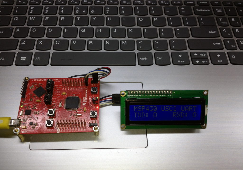
The demo here simply echoes any character data that has been sent to it from a host PC.
Demo
|
|
Hello, what software are you using for the Hardware setup images and does it support simulation for the MSP430F5529
I used Proteus VSM for drawing schematics but it doesn’t support simulation.
Hi,
Im interfacing MSP430F5529 with MAX17055 fuel guage. while reading 16 bit value, the first byte im receiving is 0. so while reading multiple registers continuously the data exchange is happening, but im getting the correct data. Can anyone suggest me what will be the issue? why im getting 0 in first byte?
read16_bit data code:
uint16_t value = 0;
USCI_B_I2C_setslaveaddress(USCI_B1_BASE, slave_address);
USCI_B_I2C_setmode(USCI_B1_BASE, USCI_B_I2C_TRANSMIT_MODE);
USCI_B_I2C_masterSendStart(USCI_B1_BASE);
while (!USCI_B_I2C_masterSendStart(USCI_B1_BASE));
USCI_B_I2C_mastterSendSingleByte(USCI_B1_BASE, reg_address);
USCI_B_I2C_setslaveaddress(USCI_B1_BASE, slave_address);
USCI_B_I2C_setmode(USCI_B1_BASE, USCI_B_I2C_TRANSMIT_MODE);
USCI_B_I2C_masterReceiveMultiByteStart(USCI_B1_BASE);
uint8_t lb = USCI_B_I2C_masterReceiveMultiByteNext(USCI_B1_BASE);
uint8_t hb = USCI_B_I2C_masterReceiveMultiByteFinish(USCI_B1_BASE);
while (USCI_B_I2C_isBusBusy(USCI_B_BASE));
value = lb << 8;
value |= hb;
return value;
In code, after sending reg address, it will be recieve mode. its a type mistake
Hi, im trying to send the command from the terminal view. i can able to send the command and tried to blink p1.0 led in msp430f5529 controller, its working fine. And im using led driver IS31FL3236A interfaced with msp430f5529 controller, i can able to interface im getting the expected output.
now i need to send the command from seriak monitor based on that command i2c communication need to start. both communication are working fine, when it runs separately. its not working when i tried to combine.
any one had any idea, why it is happening or what will be the issue?
It could be due to:
1. conflicts in clock settings
2. hardware conflict like pin mapping
3. code is getting stuck or waiting for one communication line to finish
4. use of polling method instead of interrupt-driven coding
Hi, thank you for the respose.
Do I need to use different clock initialization for I2C and UART communication? if YES, can you explain how to do that?
I mean check which clock has been set for UART and I2C…. Is it SMCLK, MCLK, etc and is it tuned to right frequency required by the respective hardware?
Is there any example on how to implement polling method in uart?
Why go for polling method when it is a blocking method of coding? It is better to use interrupts instead at least for UART receive.
yes!! currently in my code, only for uart im using interrupts to recieve command from serial monitor. Im not using interrupt for I2C communication.
so the issue is must be in clock initialization. right?
For UART, im using USCI_A1_BASE. and for I2C, im using USCI_B1_BASE.
And another thing i need to ask is, in uart when i tried blink led(p1.0) in msp430f5529 by passing command. here, without clock I’m getting output. how it is possible?
And for both i2c and uart i gave SMCLK with 1Mhz
I am surprised and happy to find this tutorial on the F5529 as TI makes a lot of different devices.
Thank you very much for putting in the extra knowledge in each segment, made reading worthwhile.
Good Work!
lovely tutorial but to be honest I don’t think I’d be investing my time on this board to start with it’s not cheap and readily available as the stm32 boards can you please do more tutorials on stm32 board’s and the stc micros thanks
Hello, I try to program MSP430FR6047 but i get error “the debug interface to the device has been secured”. when flashing using uniflash and when program using CCS this happen. can you help me to solve this problem
You can try “On connect, erase user code and unlock the device” option.
Pingback: Tinkering TI MSP430F5529 – gStore
Hello
I am doing project of msp430g2553 interface(using i2c communication) with temp 100(temperature sensor) and try to read the temperature in dispaly(16*2) but didn’t get the out put (using code composer studio) can u share me any example code for this project
Thank you sir,
Which sensor? Did you use pullup resistors for SDA-SCL pins?
Where is lcd_print.h?
All files and docs are here:
https://libstock.mikroe.com/projects/view/3233/tinkering-ti-msp430f5529
You want the truth? TI makes and sell “underpowered micros”, you know? Low everything, not only the power but also peripherals. So the price is not justified.
Otherwise, if I’ll move there, I’ll introduce them to my small hobby projects – there are still some advantages.
I may even make a visual configuration tool of my own for them…
Yeah the prices of TI products are higher than other manufacturers but I don’t think the hardware peripherals are inferior.
Not inferior but in not enough numbers compared to STM32.
True