Tinkering TI MSP430F5529

|
|
In my past tutorials on MSP430s, I demonstrated how to get started with MSP430 general purpose microcontrollers from Texas Instruments (TI). Those tutorials covered most aspects of low and mid-end MSP430G2xxx series microcontrollers. For those tutorials, TI’s official software suite – Code Composer Studio (CCS) – an Eclipse-based IDE and GRACE – a graphical peripheral initialization and configuration tool similar to STM32CubeMX were used. To me, those low and mid-end TIs chips are cool and offer best resources one can expect at affordable prices and small physical form-factors. I also briefly discussed about advanced MSP430 microcontrollers and the software resources needed to use them effectively. Given these factors, now it is high time that we start exploring an advanced 16-bit TI MSP430 microcontroller using a combination of past experiences and advanced tools. MSP430F5529 is such a robust high-end device and luckily it also comes with an affordable Launchpad board dedicated for it.
First of all, MSP430F5529 is a monster microcontroller because it offers large memory spaces– 128kB of flash and 8kB of RAM. Secondly, it is a 16-bit RISC microcontroller that host several advanced features like USB, DMA, 12-bit SAR ADC, analogue comparator, a real time clock (RTC), several sophisticated timers with multiple capture-compare I/O channels, etc. There is an on-chip hardware multiplier apart from several bidirectional general-purpose digital input-output (DIO/GPIO) pins, multipurpose communication peripherals (USCIs) and a highly complex clock and power system that can be tweaked to optimize the speed-power performances. The MSP430F5529LP microcontroller featured on-board MSP430F5529 Launchpad is a low power energy-efficient variant of MSP430F5529 and hence the LP designation at the end of the part naming. It can run at low voltage levels like 1.8V. In short, it is a hobbyist wildest dream come true.
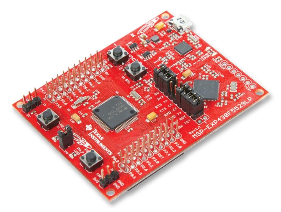
MSP-EXP430F5529LP Launchpad Board
The MSP-EXP430F5529LP Launchpad board is just like other Launchpad boards, having similar form-factor and layout. Unlike the previously seen MSP-EXP430G2 Launchpads, its header pins are brought out using dual-sided male- female rail-connectors. These allow us to stack BoosterPacks on both sides.
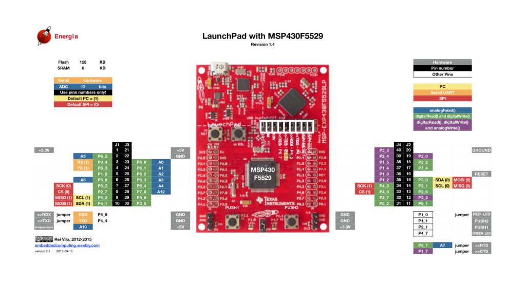
Shown above and below are the pin maps of this Launchpad board.
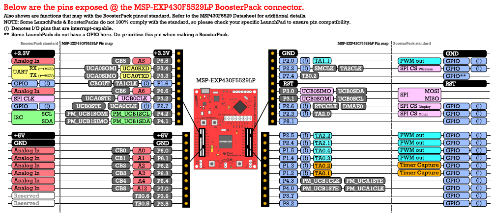
The first pin map is useful for Energia users and the second one is useful for CCS users. I use a combination of both. Like other Launchpad boards, this Launchpad comes with a separable MSP-FET USB programmer and debugger interface. Since MSP430F5529 micro has USB hardware embedded in it, the on-board micro USB port can act as a physical USB port when developing USB-based hardware. The micro USB port isn’t, however, directly connected with the chip. Instead of that, the same USB port is connected to the on-board FET programmer and the MSP430F5529 chip via an on-board USB hub. The micro USB port also provides power to the board. The on-board MSP430 chip is powered by 3.3V LDO regulator. This LDO is not meant for driving large loads. There are sufficient power rail pins to hook-up low-power external devices like sensors, LCDs, etc without the need of power rail extenders.
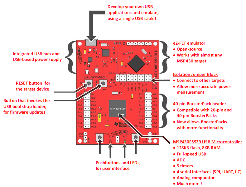
MSP430F5529 is not a low pin count micro and it has a sophisticated clock system that can be feed with both internal and external clock sources. Thus, unlike MSP430G2xxx Launchpads, this Launchpad comes with two external crystals – a 4MHz and a 32.768kHz crystal that are physically connected with GPIO pins. There are two user buttons and two LEDs also. Additionally, there are dedicated buttons for USB bootstrap loader and hardware reset. There are few jumpers that can be for measurements, debugging, programming, etc.
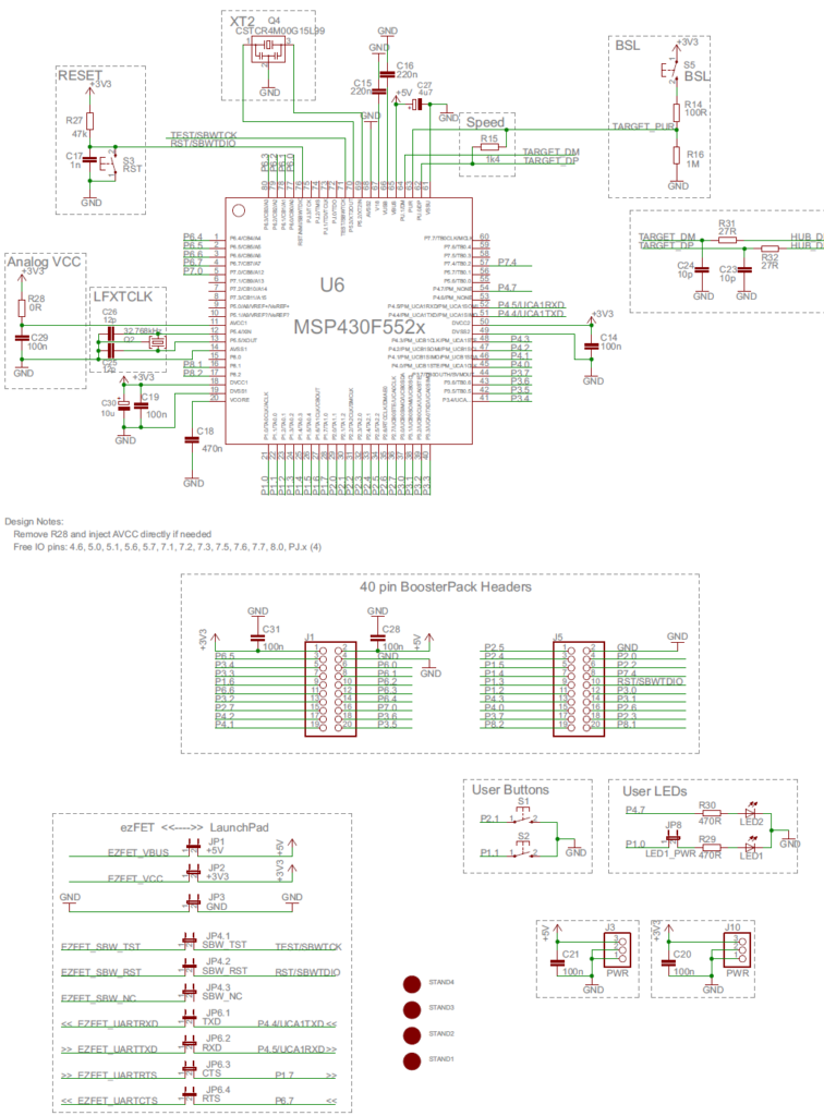
Shown below is the schematic of MSP430F5529LP Launchpad board:
TI MSP430Ware Driver Library and Other Stuffs
Like with other advanced microcontrollers from TI, there is no GRACE-like support that can be found for MSP430F5529 and similar devices. In fact, GRACE only supports few low-end and mid-end MSP430 microcontrollers and for some reason TI stopped updating this great tool since 2013. One probably reason may be the difficulty in developing a GUI-based application that can be used across all computer platforms (Windows, Linux, Mac OS, etc) while maintaining support for all ever-growing families of MSP430 devices.
Instead of upgrading GRACE, TI invested on something called MSP430Ware Driver Library or simply Driverlib. Driverlib replaces traditional register-level coding with a set of dedicated hardware libraries that reduces learning and implementation curves. These libraries consist of functions, variables and constants that have meaningful names. A sample code is shown below:
Timer_A_outputPWMParam outputPWMParam = {0};
outputPWMParam.clockSource = TIMER_A_CLOCKSOURCE_SMCLK; outputPWMParam.clockSourceDivider = TIMER_A_CLOCKSOURCE_DIVIDER_2; outputPWMParam.timerPeriod = 20000;
outputPWMParam.compareRegister = TIMER_A_CAPTURECOMPARE_REGISTER_1; outputPWMParam.compareOutputMode = TIMER_A_OUTPUTMODE_RESET_SET; outputPWMParam.dutyCycle = 0;
Timer_A_outputPWM(TIMER_A2_BASE, &outputPWMParam);
Note that there is no register-level coding involved and that’s the beauty. Here all the settings of a timer in PWM mode are being set. Each parameter is named with a meaningful name instead of some meaningless magic numbers and coding jargon.
Initially, I was doubtful and hesitant about using Driverlib because it hides away all the good-old register-level coding and at the same time it lacks good documentations. Comparing Driverlib documentation with the documentation of other manufacturers like STMicroelectronics or Microchip, I would say that Driverlib documentation is somewhat incomplete, clumsy and difficult to perceive. Adding to this is the fact that TI while developing and updating Driverlib made some changes to some function and definition names. This creates further confusion unless you are using the right version of documentation alongside the right Driverlib version.
Here’s one example. Both are correct and the compiler won’t throw any unexpected error but the first one is seen in older documentations while the second is used more often now.
Timer_A_startCounter(__MSP430_BASEADDRESS_T0A5__, TIMER_A_CONTINUOUS_MODE);

or

Timer_A_startCounter(TIMER_A0_BASE, TIMER_A_CONTINUOUS_MODE);
Issues like this one discussed above may not always be that simple and when it comes to older codes/examples, thing may become very ugly.
Another disadvantage that comes along with stuffs like Driverlib is resource management. Indeed, Driverlib reduces coding efforts a lot but at the expense of valuable and limited memory resources. Performance is also a bit compromised as execution speed is reduced due to additional hidden coding.
Despite these facts, I decided to go along with Driverlib because like other coders I didn’t want to spend time going through register-by-registers. In present day’s embedded system arena, people like the easy, effective and quick paths. It happened to me that after few trials I was able to master Driverlib and could also pinpoint issues with documentation and even practically get rid of the issues. As of this moment, I am enjoying it a lot and this whole tutorial is based on it.
Use Resource Explorer of Code Composer Studio (CCS) IDE or visit the following link:
to get access to MSP430Ware. MSP430Ware contains lot example codes, libraries and other stuffs.
The rest of the software suite and hardware tools will be same as the ones used before. Grace support is unavailable and so it won’t be used.
Please also download MSP430F5529 documentations and Launchpad board resources.
|
|
Hello, what software are you using for the Hardware setup images and does it support simulation for the MSP430F5529
I used Proteus VSM for drawing schematics but it doesn’t support simulation.
Hi,
Im interfacing MSP430F5529 with MAX17055 fuel guage. while reading 16 bit value, the first byte im receiving is 0. so while reading multiple registers continuously the data exchange is happening, but im getting the correct data. Can anyone suggest me what will be the issue? why im getting 0 in first byte?
read16_bit data code:
uint16_t value = 0;
USCI_B_I2C_setslaveaddress(USCI_B1_BASE, slave_address);
USCI_B_I2C_setmode(USCI_B1_BASE, USCI_B_I2C_TRANSMIT_MODE);
USCI_B_I2C_masterSendStart(USCI_B1_BASE);
while (!USCI_B_I2C_masterSendStart(USCI_B1_BASE));
USCI_B_I2C_mastterSendSingleByte(USCI_B1_BASE, reg_address);
USCI_B_I2C_setslaveaddress(USCI_B1_BASE, slave_address);
USCI_B_I2C_setmode(USCI_B1_BASE, USCI_B_I2C_TRANSMIT_MODE);
USCI_B_I2C_masterReceiveMultiByteStart(USCI_B1_BASE);
uint8_t lb = USCI_B_I2C_masterReceiveMultiByteNext(USCI_B1_BASE);
uint8_t hb = USCI_B_I2C_masterReceiveMultiByteFinish(USCI_B1_BASE);
while (USCI_B_I2C_isBusBusy(USCI_B_BASE));
value = lb << 8;
value |= hb;
return value;
In code, after sending reg address, it will be recieve mode. its a type mistake
Hi, im trying to send the command from the terminal view. i can able to send the command and tried to blink p1.0 led in msp430f5529 controller, its working fine. And im using led driver IS31FL3236A interfaced with msp430f5529 controller, i can able to interface im getting the expected output.
now i need to send the command from seriak monitor based on that command i2c communication need to start. both communication are working fine, when it runs separately. its not working when i tried to combine.
any one had any idea, why it is happening or what will be the issue?
It could be due to:
1. conflicts in clock settings
2. hardware conflict like pin mapping
3. code is getting stuck or waiting for one communication line to finish
4. use of polling method instead of interrupt-driven coding
Hi, thank you for the respose.
Do I need to use different clock initialization for I2C and UART communication? if YES, can you explain how to do that?
I mean check which clock has been set for UART and I2C…. Is it SMCLK, MCLK, etc and is it tuned to right frequency required by the respective hardware?
Is there any example on how to implement polling method in uart?
Why go for polling method when it is a blocking method of coding? It is better to use interrupts instead at least for UART receive.
yes!! currently in my code, only for uart im using interrupts to recieve command from serial monitor. Im not using interrupt for I2C communication.
so the issue is must be in clock initialization. right?
For UART, im using USCI_A1_BASE. and for I2C, im using USCI_B1_BASE.
And another thing i need to ask is, in uart when i tried blink led(p1.0) in msp430f5529 by passing command. here, without clock I’m getting output. how it is possible?
And for both i2c and uart i gave SMCLK with 1Mhz
I am surprised and happy to find this tutorial on the F5529 as TI makes a lot of different devices.
Thank you very much for putting in the extra knowledge in each segment, made reading worthwhile.
Good Work!
lovely tutorial but to be honest I don’t think I’d be investing my time on this board to start with it’s not cheap and readily available as the stm32 boards can you please do more tutorials on stm32 board’s and the stc micros thanks
Hello, I try to program MSP430FR6047 but i get error “the debug interface to the device has been secured”. when flashing using uniflash and when program using CCS this happen. can you help me to solve this problem
You can try “On connect, erase user code and unlock the device” option.
Pingback: Tinkering TI MSP430F5529 – gStore
Hello
I am doing project of msp430g2553 interface(using i2c communication) with temp 100(temperature sensor) and try to read the temperature in dispaly(16*2) but didn’t get the out put (using code composer studio) can u share me any example code for this project
Thank you sir,
Which sensor? Did you use pullup resistors for SDA-SCL pins?
Where is lcd_print.h?
All files and docs are here:
https://libstock.mikroe.com/projects/view/3233/tinkering-ti-msp430f5529
You want the truth? TI makes and sell “underpowered micros”, you know? Low everything, not only the power but also peripherals. So the price is not justified.
Otherwise, if I’ll move there, I’ll introduce them to my small hobby projects – there are still some advantages.
I may even make a visual configuration tool of my own for them…
Yeah the prices of TI products are higher than other manufacturers but I don’t think the hardware peripherals are inferior.
Not inferior but in not enough numbers compared to STM32.
True