Mastering the SiLabs C8051 Microcontroller
|
|
Analogue-to-Digital Converter (ADC) – Analogue Thermometer
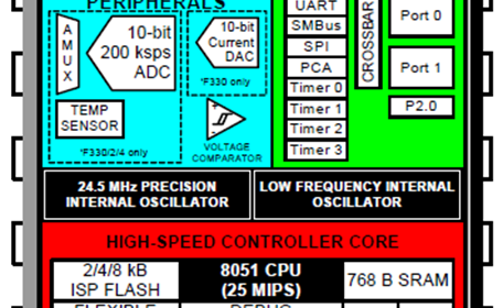
An Analogue-to-Digital Converter (ADC) is a must in any modern-era microcontroller and fortunately, C8051s come with 10-bit 200kbps differential successive-approximation register (SAR) ADCs, unlike traditional ones which are fully digital devices. It is quite advanced in terms of features. In the case of C8051F330D, all pins can be used with it. Two internal analogue multiplexers take care of the pin selection task. Additionally, there is an internal temperature sensor, an internal reference source, an analogue window comparator and tons of other kinds of stuff. The ADC can be triggered by several sources and it also supports interrupts. However, the best features of this ADC are the support for differential inputs and its SAR-type build-up. SAR ADCs are fast compared to other ADC types. The block diagram of the internal ADC of C8051F330D is shown below:
Code
 #define LED_DOUT  P1_6_bit
 #define LED_CLK   P1_5_bit
 #define LED_LATCH P1_7_bit

 #define ADC_res    1023.0
 #define VDD_mv     3300.0

 unsigned char i = 0;
 unsigned char pt = 0;
 register unsigned char val = 0;
 unsigned int value = 0;

 const unsigned char code segment_code[12] =
 {
   0xC0, // 0
   0xF9, // 1
   0xA4, // 2
   0xB0, // 3
   0x99, // 4
   0x92, // 5
   0x82, // 6
   0xF8, // 7
   0x80, // 8
   0x90, // 9
   0x7F, // .
   0xBF  // -
 };

 const unsigned char code display_pos[4] =
 {
   0xF7, //1st Display
   0xFB, //2nd Display
   0xFD, //3rd Display
   0xFE  //4th Display
 };

 void PCA_Init(void);
 void Timer_Init();
 void Port_IO_Init();
 void Oscillator_Init();
 void Interrupts_Init();
 void ADC_Init(void);
 void Init_Device(void);
 void write_74HC595(unsigned char send_data);
 void segment_write(unsigned char disp, unsigned char pos, unsigned char point);
 unsigned int adc_read(void);
 void Voltage_Reference_Init(void);
 unsigned int adc_avg(unsigned char channel);

 void Timer_ISR(void)
 iv IVT_ADDR_ET3
 ilevel 0
 ics ICS_AUTO
 {
     switch(i)
     {
         case 0:
         {
             val = (value / 1000);
             pt = 0;
             break;
         }
         case 1:
         {
             val = ((value % 1000) / 100);
             pt = 1;
             break;
         }
         case 2:
         {
             val = ((value % 100) / 10);
             pt = 0;
             break;
         }
         case 3:
         {
             val = (value % 10);
             pt = 0;
             break;
         }
     }

     segment_write(val, i, pt);

     i++;

     if(i > 3)
     {
        i = 0;
     }

     TMR3CN &= 0x7F;
 }

 void main(void)
 {
   float t = 0;

   Init_Device();

   while(1)
   {
      t = (adc_avg(0) * VDD_mv);
      t /= ADC_res;
      value = ((t * 10) – 5000);
      delay_ms(100);
   };
 }

 void PCA_Init(void)
 {
     PCA0MD &= ~0x40;
     PCA0MD = 0x00;
 }

 void Timer_Init()
 {
     TMR3CN = 0x04;
     TMR3RLL = 0x02;
     TMR3RLH = 0xFC;
 }

 void Port_IO_Init()
 {
     // P0.0  -  Skipped,     Open-Drain, Analog
     // P0.1  -  Unassigned,  Open-Drain, Digital
     // P0.2  -  Unassigned,  Open-Drain, Digital
     // P0.3  -  Unassigned,  Open-Drain, Digital
     // P0.4  -  Unassigned,  Open-Drain, Digital
     // P0.5  -  Unassigned,  Open-Drain, Digital
     // P0.6  -  Unassigned,  Open-Drain, Digital
     // P0.7  -  Unassigned,  Open-Drain, Digital

     // P1.0  -  Unassigned,  Open-Drain, Digital
     // P1.1  -  Unassigned,  Open-Drain, Digital
     // P1.2  -  Unassigned,  Open-Drain, Digital
     // P1.3  -  Unassigned,  Open-Drain, Digital
     // P1.4  -  Unassigned,  Open-Drain, Digital
     // P1.5  -  Skipped,     Push-Pull,  Digital
     // P1.6  -  Skipped,     Push-Pull,  Digital
     // P1.7  -  Skipped,     Push-Pull,  Digital

     P0MDIN = 0xFE;
     P1MDOUT = 0xE0;
     P0SKIP = 0x01;
     P1SKIP = 0xE0;
     XBR1 = 0x40;
 }

 void Oscillator_Init()
 {
     OSCLCN = 0x82;
 }

 void Interrupts_Init()
 {
     IE = 0x80;
     EIE1 = 0x80;
 }

 void ADC_Init(void)
 {
     AMX0P = 0x00;
     AMX0N = 0x11;
     ADC0CF = 0x58;
     ADC0CN = 0x80;
 }

 void Voltage_Reference_Init(void)
 {
     REF0CN = 0x0A;
 }

 void Init_Device(void)
 {
     PCA_Init();
     Timer_Init();
     Port_IO_Init();
     Oscillator_Init();
     Interrupts_Init();
     ADC_Init();
     Voltage_Reference_Init();
 }

 void write_74HC595(unsigned char send_data)
 {
     signed char clks = 8;

     while(clks > 0)
     {
         if((send_data & 0x80) == 0x00)
         {
           LED_DOUT = 0;
         }
         else
         {
           LED_DOUT = 1;
         }

         LED_CLK = 0;
         send_data <<= 1;
         clks--;
         LED_CLK = 1;
     }
 }

 void segment_write(unsigned char disp, unsigned char pos, unsigned char point)
 {
     unsigned char write_value = segment_code[disp];

     if(point)
     {
         write_value &= segment_code[10];
     }

     LED_LATCH = 0;
     write_74HC595(write_value);
     write_74HC595(display_pos[pos]);
     LED_LATCH = 1;
 }

 unsigned int adc_read(void)
 {
    unsigned int ad_value = 0;

    ad_value = ADC0H;
    ad_value <<= 8;
    ad_value |= ADC0L;

    return ad_value;
 }

 unsigned int adc_avg(unsigned char channel)
 {
     unsigned int avg_value = 0;
     signed char samples = 16;

     AMX0P = (channel & 0x1F);
     delay_ms(1);

     while(samples > 0)
     {
         AD0INT_bit = 0;
         AD0BUSY_bit = 1;

         while(AD0INT_bit == 0);
         avg_value += adc_read();

         samples--;
     };

     avg_value >>= 4;

     return avg_value;
 }
Schematic
Explanation
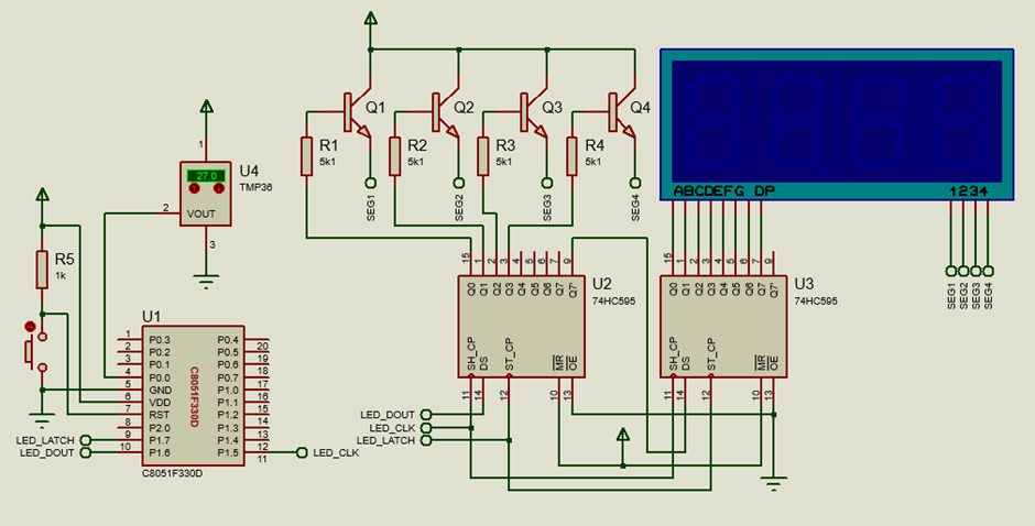
TMP36 is a very popular analogue temperature sensor apart from LM35. It gives voltage output that is proportional to temperature and has an accuracy of 10mV/°C. With an ADC we can read this sensor and determine the temperature it is sensing.
Firstly, we have to declare the pin that we will be using with the ADC. In this example, P0.0 pin is used and so it is set as open-drain analogue input.
 void Port_IO_Init()
 {
     // P0.0  -  Skipped,     Open-Drain, Analog
     // P0.1  -  Unassigned,  Open-Drain, Digital
     // P0.2  -  Unassigned,  Open-Drain, Digital
     // P0.3  -  Unassigned,  Open-Drain, Digital
     // P0.4  -  Unassigned,  Open-Drain, Digital
     // P0.5  -  Unassigned,  Open-Drain, Digital
     // P0.6  -  Unassigned,  Open-Drain, Digital
     // P0.7  -  Unassigned,  Open-Drain, Digital

     // P1.0  -  Unassigned,  Open-Drain, Digital
     // P1.1  -  Unassigned,  Open-Drain, Digital
     // P1.2  -  Unassigned,  Open-Drain, Digital
     // P1.3  -  Unassigned,  Open-Drain, Digital
     // P1.4  -  Unassigned,  Open-Drain, Digital
     // P1.5  -  Skipped,     Push-Pull,  Digital
     // P1.6  -  Skipped,     Push-Pull,  Digital
     // P1.7  -  Skipped,     Push-Pull,  Digital

     P0MDIN = 0xFE;
     P1MDOUT = 0xE0;
     P0SKIP = 0x01;
     P1SKIP = 0xE0;
     XBR1 = 0x40;
 }
Like most of the examples, the system clock is derived from the internal RC oscillator and is set to 12.25MHz.
 void Oscillator_Init()
 {
     OSCLCN = 0x82;
 }
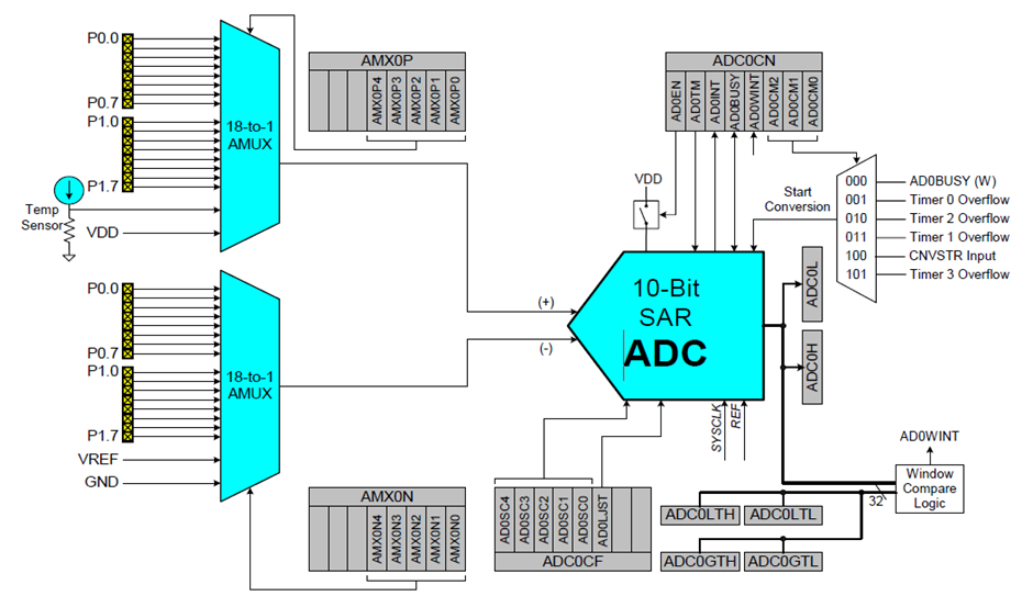
Note that the ADC is differential in terms of input. Since we are using only one channel, i.e., the positive input of the ADC, the negative input has to be tied to the ground. The ADC clock is set to 1MHz which is good enough for most applications considering Nyquist theory. Software-based trigger-polling method is used. ADC readings are set to be right-justified. These all are set as per the ADC initialization code shown below:
 void ADC_Init(void)
 {
     AMX0P = 0x00;
     AMX0N = 0x11;
     ADC0CF = 0x58;
     ADC0CN = 0x80;
 }
All ADC measurements have to be done with respect to a reference voltage source and in this example, VDD is used as the reference source. Internal analogue peripherals need to be biased by the internal bias generator. All these are part of the internal reference source peripheral and so these settings are set by tweaking the internal reference source configuration register.
 void Voltage_Reference_Init(void)
 {
     REF0CN = 0x0A;
 }
The ADC can be read using the following function. It lets the user select a single channel and take an average of 16 samples. The ADC is first triggered by a software trigger and then the ADC conversion completion flag is polled. After polling, the ADC is read. The ADC readings are summed and stored. After acquiring 16 samples, the summed reading is right-shifted by a factor of 4. This shifting is just like dividing by 16 because 2^4 = 16.
 unsigned int adc_avg(unsigned char channel)
 {
     unsigned int avg_value = 0;
     signed char samples = 16;

     AMX0P = (channel & 0x1F);
     delay_ms(1);

     while(samples > 0)
     {
         AD0INT_bit = 0;
         AD0BUSY_bit = 1;

         while(AD0INT_bit == 0);
         avg_value += adc_read();

         samples--;
     };

     avg_value >>= 4;

     return avg_value;
 }
Since the ADC reading is right-justified, the 10-bit ADC reading is done as follows:
 unsigned int adc_read(void)
 {
    unsigned int ad_value = 0;

    ad_value = ADC0H;
    ad_value <<= 8;
    ad_value |= ADC0L;

    return ad_value;
 }
The high byte is read first and then the low byte is read.
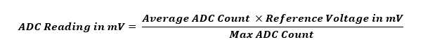
Inside the main loop, the average ADC reading is obtained and the ADC count is converted to millivolts. The millivolt value is then converted to temperature.
 void main(void)
 {
   float t = 0;

   Init_Device();

   while(1)
   {
      t = (adc_avg(0) * VDD_mv);
      t /= ADC_res;
      value = ((t * 10) – 5000);
      delay_ms(100);
   };
 }
The math behind these steps in as follows.
First, we need to determine the voltage output from the sensor. This is done using the formula below:
If we check the datasheet of the TMP36 sensor, we can see the sensor output voltage vs temperature relation along with the output scaling voltage and offset voltage values.
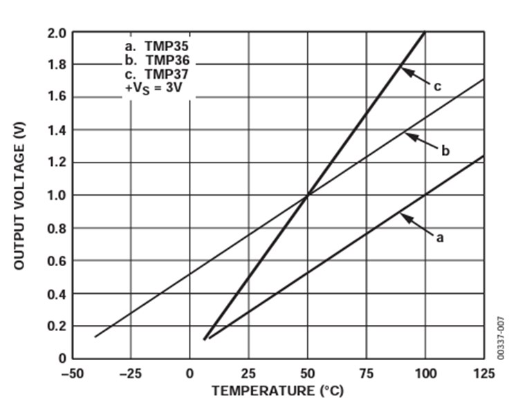
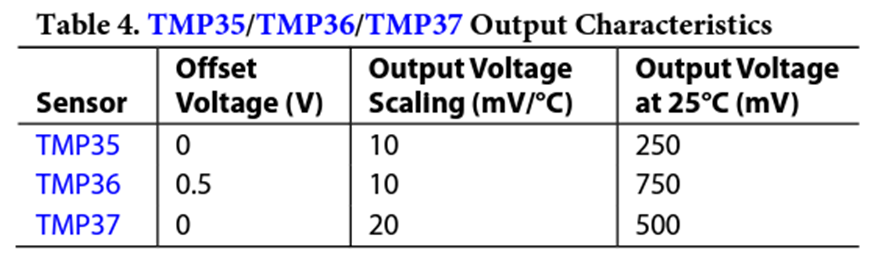
Using the graph and the info above, we can determine the following temperature versus voltage relation:

To display the temperature on the onboard seven-segment display, the above equation is scaled by a factor of 100 and so it changes to the following:

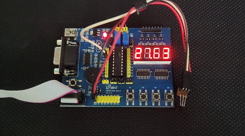
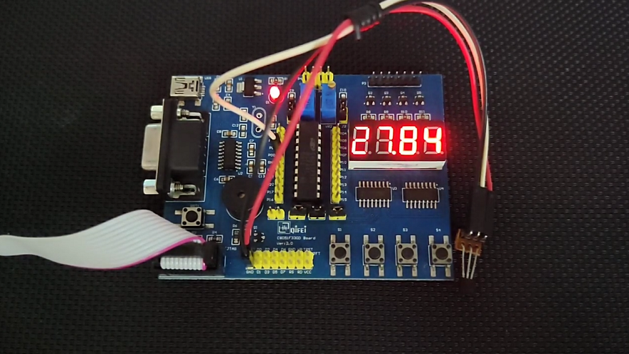
Demo
|
|
Thanks for the feedback….