Mastering the SiLabs C8051 Microcontroller
|
|
One Wire Bus (OW) – DS18B20 Digital Temperature Sensor
MikroC compiler packs a lot of common regular-use libraries apart from SPI, UART and I2C libraries. One wire library is one such library that is not usually seen in other compilers. This library allows us to communicate with one-wire devices from Dallas like DS18B20 digital temperature sensors and other one-wire devices from the same manufacturer.
Code
 #define LED_DOUT                        P1_6_bit
 #define LED_CLK                         P1_5_bit
 #define LED_LATCH                       P1_7_bit

 #define DS18B20_CONVERT_T               0x44
 #define DS18B20_READ_SCRATCHPAD         0xBE
 #define DS18B20_SKIP_ROM                0xCC

 sbit OW_Bit at P1_4_bit;

 unsigned char i = 0;
 register unsigned char val = 0;
 unsigned int value = 0;

 const unsigned char code segment_code[12] =
 {
   0xC0, // 0
   0xF9, // 1
   0xA4, // 2
   0xB0, // 3
   0x99, // 4
   0x92, // 5
   0x82, // 6
   0xF8, // 7
   0x80, // 8
   0x90, // 9
   0x9C, // degree
   0xC6  // C
 };

 const unsigned char code display_pos[4] =
 {
   0xF7, //1st Display
   0xFB, //2nd Display
   0xFD, //3rd Display
   0xFE  //4th Display
 };

 void Reset_Sources_Init(void);
 void PCA_Init(void);
 void Timer_Init(void);
 void Port_IO_Init(void);
 void Oscillator_Init(void);
 void Interrupts_Init(void);
 void Init_Device(void);
 void write_74HC595(unsigned char send_data);
 void segment_write(unsigned char disp, unsigned char pos);

 void Timer_ISR(void)
 iv IVT_ADDR_ET3
 ilevel 1
 ics ICS_AUTO
 {
     switch(i)
     {
         case 0:
         {
             val = (value / 10);
             break;
         }
         case 1:
         {
             val = (value % 10);
             break;
         }
         case 2:
         {
             val = 10;
             break;
         }
         case 3:
         {
             val = 11;
             break;
         }
     }

     segment_write(val, i);
     i++;

     if(i > 3)
     {
        i = 0;
     }

     TMR3CN &= 0x7F;
 }

 void main(void)
 {
     unsigned temp = 0x00;
     Init_Device();

     while(1)
     {
         Ow_Reset();
         Ow_Write(DS18B20_SKIP_ROM);
         Ow_Write(DS18B20_CONVERT_T);
         Delay_us(120);

         Ow_Reset();
         Ow_Write(DS18B20_SKIP_ROM);
         Ow_Write(DS18B20_READ_SCRATCHPAD);

         temp =  Ow_Read();
         temp = ((Ow_Read() << 0x08) + temp);
         value = temp >> 0x04;

         P0_1_bit = 1;
         delay_ms(300);
         P0_1_bit = 0;
         delay_ms(300);

     }
 }

 void Reset_Sources_Init(void)
 {
     RSTSRC = 0x04;
 }

 void PCA_Init(void)
 {
     PCA0MD &= ~0x40;
     PCA0MD = 0x00;
 }

 void Timer_Init(void)
 {
     TMR3CN = 0x04;
     TMR3RLL = 0xCA;
     TMR3RLH = 0xFA;
 }


 void Port_IO_Init(void)
 {
     // P0.0  -  Unassigned,  Open-Drain, Digital
     // P0.1  -  Skipped,     Push-Pull,  Digital
     // P0.2  -  Skipped,     Open-Drain, Analog
     // P0.3  -  Skipped,     Open-Drain, Analog
     // P0.4  -  Unassigned,  Open-Drain, Digital
     // P0.5  -  Unassigned,  Open-Drain, Digital
     // P0.6  -  Unassigned,  Open-Drain, Digital
     // P0.7  -  Unassigned,  Open-Drain, Digital

     // P1.0  -  Unassigned,  Open-Drain, Digital
     // P1.1  -  Unassigned,  Open-Drain, Digital
     // P1.2  -  Unassigned,  Open-Drain, Digital
     // P1.3  -  Unassigned,  Open-Drain, Digital
     // P1.4  -  Skipped,     Open-Drain, Digital
     // P1.5  -  Unassigned,  Push-Pull,  Digital
     // P1.6  -  Skipped,     Push-Pull,  Digital
     // P1.7  -  Skipped,     Push-Pull,  Digital

     P0MDIN = 0xF3;
     P0MDOUT = 0x02;
     P1MDOUT = 0xE0;
     P0SKIP = 0x0E;
     P1SKIP = 0xD0;
     XBR1 = 0x40;
 }

 void Oscillator_Init(void)
 {
     int i = 0;
     OSCICN = 0x81;

     if(MCDRSF_bit == 1)
     {
         CLKSEL = 0x00;

         for(i = 0; i < 9; i++)
         {
             P0_1_bit = 1;
             delay_ms(60);
             P0_1_bit = 0;
             delay_ms(60);
         }
     }
     else
     {
         OSCXCN = 0x67;
         for (i = 0; i < 3000; i++);  // Wait 1ms for initialization
         while ((OSCXCN & 0x80) == 0);
         CLKSEL = 0x01;

         for(i = 0; i < 9; i++)
         {
             P0_1_bit = 1;
             delay_ms(45);
             P0_1_bit = 0;
             delay_ms(45);
         }
     }

     delay_ms(2000);
 }

 void Interrupts_Init(void)
 {
     IE = 0x80;
     EIE1 = 0x80;
 }

 void Init_Device(void)
 {
     PCA_Init();
     Timer_Init();
     Port_IO_Init();
     Oscillator_Init();
     Reset_Sources_Init();
     Interrupts_Init();
 }

 void write_74HC595(unsigned char send_data)
 {
     signed char clks = 8;

     while(clks > 0)
     {
         if((send_data & 0x80) == 0x00)
         {
           LED_DOUT = 0;
         }
         else
         {
           LED_DOUT = 1;
         }

         LED_CLK = 0;
         send_data <<= 1;
         clks--;
         LED_CLK = 1;
     }
 }

 void segment_write(unsigned char disp, unsigned char pos)
 {
     LED_LATCH = 0;
     write_74HC595(segment_code[disp]);
     write_74HC595(display_pos[pos]);
     LED_LATCH = 1;
 }
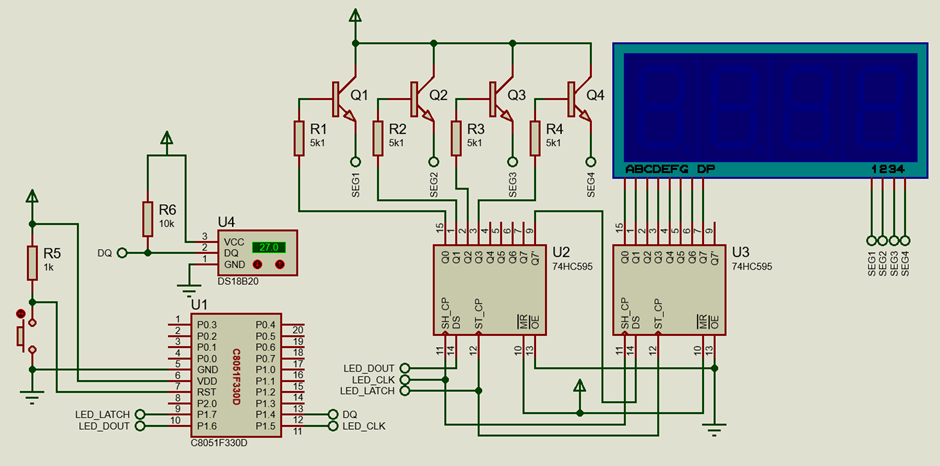
Schematic
Explanation
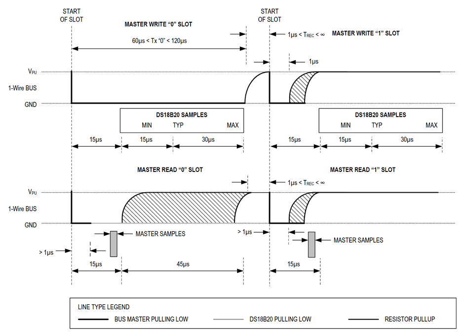
DS18B20 digital temperature sensor employs a time-slotting mechanism for data transactions, the basics of which are shown below.
MikroC compiler has a dedicated one-wire library for this sensor and many other devices that employ one-wire protocol as per specification from Dallas. In this example, I used their library to communicate with a DS18B20 temperature sensor and the entire process is very simple.
The main code begins by issuing one-wire reset command (Ow_Reset) followed by ROM skipping and temperature convert commands. The reset command acts like a flush. The ROM skip command is used because there is only one DS18B20 present in the one-wire bus in this example. If there were multiple sensors present in the same bus then we could identify them by reading their unique identification code stored inside their ROMs. The “temperature convert” command, on the other hand, reads the internal ADC of the sensor and converts the analogue temperature value to digital binary data. After this, we have to wait for a small duration of 120 microseconds.
The above process is repeated but the temperature conversion command is replaced with the scratchpad read command because the converted temperature binary data is stored in an internal scratchpad or RAM location. The sensor is read and necessary conversions are done to extract temperature in human-readable decimal format. The temperature is then displayed on the onboard seven-segment display.
 void main(void)
 {
     unsigned temp = 0x00;
     Init_Device();

     while(1)
     {
         Ow_Reset();
         Ow_Write(DS18B20_SKIP_ROM);
         Ow_Write(DS18B20_CONVERT_T);
         Delay_us(120);

         Ow_Reset();
         Ow_Write(DS18B20_SKIP_ROM);
         Ow_Write(DS18B20_READ_SCRATCHPAD);

         temp =  Ow_Read();
         temp = ((Ow_Read() << 0x08) + temp);
         value = temp >> 0x04;

         P0_1_bit = 1;
         delay_ms(300);
         P0_1_bit = 0;
         delay_ms(300);

     }
 }
There is one thing in the code that needs to be discussed here. In this example code, I used a trick to ensure that the program works even if the 12MHz external oscillator attached to the microcontroller fails for some reason. For this, I enabled the missing clock detector reset. It works simply by resetting the microcontroller in the event of a missing clock signal from an external oscillator. After a reset or during start-up, the code checks whether there is a history of reset due to external oscillator failure or not. This is done by checking the MCDESF flag bit. If there was a reset due to external oscillator failure then the code switches to the internal oscillator automatically or else the external oscillator is selected. The oscillator selection is shown by flashing a LED connected with P0.1 pin. The flashing rate indicates which clock source has been selected. A fast flash rate indicates external oscillator selection while a slow flash rate indicates internal oscillator selection.
 void Reset_Sources_Init(void)
 {
     RSTSRC = 0x04;
 }

 ....

 void Oscillator_Init(void)
 {
     int i = 0;
     OSCICN = 0x81;

     if(MCDRSF_bit == 1)
     {
         CLKSEL = 0x00;

         for(i = 0; i < 9; i++)
         {
             P0_1_bit = 1;
             delay_ms(60);
             P0_1_bit = 0;
             delay_ms(60);
         }
     }
     else
     {
         OSCXCN = 0x67;
         for (i = 0; i < 3000; i++);  // Wait 1ms for initialization
         while ((OSCXCN & 0x80) == 0);
         CLKSEL = 0x01;

         for(i = 0; i < 9; i++)
         {
             P0_1_bit = 1;
             delay_ms(45);
             P0_1_bit = 0;
             delay_ms(45);
         }
     }

     delay_ms(2000);
 }
Demo
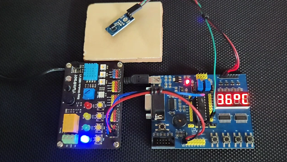
|
|
Thanks for the feedback….