Mastering the SiLabs C8051 Microcontroller
|
|
SPI – MAX31865 PT100 RTD Amplifier
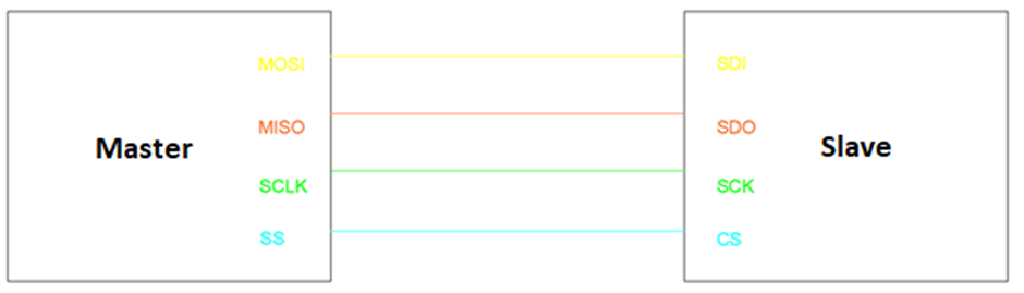
Serial Peripheral Interface (SPI) communication is a multi-wire high-speed short-distance synchronous communication method. Three (half-duplex) or four (full-duplex) pins is all that are needed to establish communication between a host (master) and a slave. These pins are as follows:
- Master-In-Slave-Out (MIS0) connected to Slave-Data-Out (SDO).
- Master-Out-Slave-In (MOSI) connected to Slave-Data-In (SDI).
- Serial Clock (SCLK) connected to Slave Clock (SCK).
- Slave Select (SS) connected to Chip Select (CS).
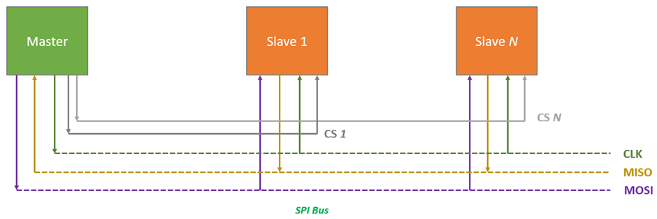
Multiple slaves can be present in a common SPI bus but their chip-select pins have to be different. This is where SPI communication falls behind UART and I2C communications. However, the raw speed advantage makes SPI the number one choice for displays, flash memories, sensors, etc.
To know more about SPI bus, the following links are very informative:
- https://learn.mikroe.com/spi-bus
- https://learn.sparkfun.com/tutorials/serial-peripheral-interface-spi
- http://ww1.microchip.com/downloads/en/devicedoc/spi.pdf
- http://tronixstuff.com/2011/05/13/tutorial-arduino-and-the-spi-bus
- https://www.analog.com/en/analog-dialogue/articles/introduction-to-spi-interface.html
- http://www.circuitbasics.com/basics-of-the-spi-communication-protocol
Code
MAX31865.h
 #define MAX31865_CONFIG_REG                  0x00
 #define MAX31865_RTD_MSB_REG                 0x01
 #define MAX31865_RTD_LSB_REG                 0x02
 #define MAX31865_HFAULT_MSB_REG              0x03
 #define MAX31865_HFAULT_LSB_REG              0x04
 #define MAX31865_LFAULT_MSB_REG              0x05
 #define MAX31865_LFAULT_LSB_REG              0x06
 #define MAX31865_FAULT_STATUS_REG            0x07

 /* Configuration Definitions */
 #define MAX31865_CONFIG_BIAS                 0x80
 #define MAX31865_CONFIG_MODE_AUTO            0x40
 #define MAX31865_CONFIG_MODE_OFF             0x00
 #define MAX31865_CONFIG_1SHOT                0x20
 #define MAX31865_CONFIG_3_WIRE               0x10
 #define MAX31865_CONFIG_24_WIRE              0x00
 #define MAX31865_CONFIG_FAULT_STATUS         0x02
 #define MAX31865_CONFIG_FILTER_50Hz          0x01
 #define MAX31865_CONFIG_FILTER_60Hz          0x00

 /* Fault Definitions */
 #define MAX31865_FAULT_HIGH_THRESHOLD        0x80
 #define MAX31865_FAULT_LOW_THRESHOLD         0x40
 #define MAX31865_FAULT_REF_IN_LOW            0x20
 #define MAX31865_FAULT_REF_IN_HIGH           0x10
 #define MAX31865_FAULT_RTD_IN_LOW            0x08
 #define MAX31865_FAULT_OV_UV                 0x04

 #define MAX31865_RTD_A                       0.00390803
 #define MAX31865_RTD_B                       -0.000000577
 #define MAX31865_Reference_Resistance        430.0
 #define MAX31865_RTD_Nominal_Value           100.0 // for PT100

 #define MAX31865_CS                          P0_3_bit

 void MAX31865_init(void);
 unsigned char MAX31865_read_byte(unsigned char address);
 unsigned int MAX31865_read_word(unsigned char address);
 void MAX31865_write_byte(unsigned char address, unsigned char value);
 void MAX31865_write_word(unsigned char address, unsigned char lb, unsigned char hb);
 unsigned int MAX31865_get_RTD(void);
 signed int MAX31865_get_temperature(void);
MAX31865.c
 #include "MAX31865.h"

 void MAX31865_init(void)
 {
     SPI1_Init_Advanced(1000000, _SPI_CLK_IDLE_LO | _SPI_CLK_ACTIVE_2_IDLE | _SPI_MASTER);
     delay_ms(10);

     MAX31865_CS = 1;

     MAX31865_write_byte(MAX31865_CONFIG_REG, \
                         MAX31865_CONFIG_BIAS | \
                         MAX31865_CONFIG_MODE_AUTO | \
                         MAX31865_CONFIG_3_WIRE | \
                         MAX31865_CONFIG_FAULT_STATUS | \
                         MAX31865_CONFIG_FILTER_50Hz);
 }

 unsigned char MAX31865_read_byte(unsigned char address)
 {
     unsigned char retval = 0x00;

     MAX31865_CS = 0;
     SPI_Write(address & 0x7F);
     retval = SPI_Read(0x00);
     MAX31865_CS = 1;

     return retval;
 }

 unsigned int MAX31865_read_word(unsigned char address)
 {
     unsigned char lb = 0x00;
     unsigned char hb = 0x00;
     unsigned int retval = 0x0000;

     hb = MAX31865_read_byte(address);
     lb = MAX31865_read_byte(address + 1);

     retval = hb;
     retval <<= 0x08;
     retval |= lb;

     return retval;
 }

 void MAX31865_write_byte(unsigned char address, unsigned char value)
 {
     MAX31865_CS = 0;
     SPI_Write(address | 0x80);
     SPI_Write(value);
     MAX31865_CS = 1;
 }

 void MAX31865_write_word(unsigned char address, unsigned char lb, unsigned char hb)
 {
     MAX31865_write_byte(address, hb);
     MAX31865_write_byte((address + 1), lb);
 }

 unsigned int MAX31865_get_RTD(void)
 {
   unsigned int rtd_value = 0x00;

   rtd_value = MAX31865_read_word(MAX31865_RTD_MSB_REG);
   rtd_value >>= 1;

   return rtd_value;
 }

 signed int MAX31865_get_temperature(void)
 {
     float rt = 0.0;
     signed int t_value = 0;

     t_value = MAX31865_get_RTD();
     rt = (MAX31865_Reference_Resistance * t_value);
     rt /= 32768.0;

     rt /= MAX31865_RTD_Nominal_Value;
     rt = (rt - 1.0);
     t_value = (rt / MAX31865_RTD_A);

     return t_value;
 }
main.c
 #include "MAX31865.c"

 #define LED_DOUT          P1_6_bit
 #define LED_CLK           P1_5_bit
 #define LED_LATCH         P1_7_bit

 unsigned char i = 0;
 register unsigned char val = 0;
 unsigned int value = 0;

 const unsigned char code segment_code[12] =
 {
   0xC0, // 0
   0xF9, // 1
   0xA4, // 2
   0xB0, // 3
   0x99, // 4
   0x92, // 5
   0x82, // 6
   0xF8, // 7
   0x80, // 8
   0x90, // 9
   0x9C, // degree
   0xC6  // C
 };

 const unsigned char code display_pos[4] =
 {
   0xF7, //1st Display
   0xFB, //2nd Display
   0xFD, //3rd Display
   0xFE  //4th Display
 };

 void PCA_Init(void);
 void Timer_Init(void);
 void SPI_Init(void);
 void Port_IO_Init(void);
 void Oscillator_Init(void);
 void Init_Device(void);
 void write_74HC595(unsigned char send_data);
 void segment_write(unsigned char disp, unsigned char pos);

 void Timer_ISR()
 iv IVT_ADDR_ET3
 ilevel 1
 ics ICS_AUTO
 {
     switch(i)
     {
         case 0:
         {
             val = (value / 10);
             break;
         }
         case 1:
         {
             val = (value % 10);
             break;
         }
         case 2:
         {
             val = 10;
             break;
         }
         case 3:
         {
             val = 11;
             break;
         }
     }

     segment_write(val, i);

     i++;

     if(i > 3)
     {
        i = 0;
     }

     TMR3CN &= 0x7F;
 }

 void main(void)
 {
     Init_Device();
     MAX31865_init();

     while(1)
     {
         value = MAX31865_get_temperature();
         delay_ms(600);
     };
 }

 void PCA_Init(void)
 {
     PCA0MD &= ~0x40;
     PCA0MD = 0x00;
 }

 void Timer_Init(void)
 {
     TMR3CN = 0x04;
     TMR3RLL = 0x02;
     TMR3RLH = 0xFC;
 }

 void SPI_Init(void)
 {
     SPI0CFG = 0x40;
     SPI0CN = 0x01;
     SPI0CKR = 0x05;
 }

 void Port_IO_Init(void)
 {
     // P0.0  -  SCK  (SPI0), Push-Pull,  Digital
     // P0.1  -  MISO (SPI0), Open-Drain, Digital
     // P0.2  -  MOSI (SPI0), Push-Pull,  Digital
     // P0.3  -  Skipped,     Push-Pull,  Digital
     // P0.4  -  Unassigned,  Open-Drain, Digital
     // P0.5  -  Unassigned,  Open-Drain, Digital
     // P0.6  -  Unassigned,  Open-Drain, Digital
     // P0.7  -  Unassigned,  Open-Drain, Digital

     // P1.0  -  Unassigned,  Open-Drain, Digital
     // P1.1  -  Unassigned,  Open-Drain, Digital
     // P1.2  -  Unassigned,  Open-Drain, Digital
     // P1.3  -  Unassigned,  Open-Drain, Digital
     // P1.4  -  Unassigned,  Open-Drain, Digital
     // P1.5  -  Skipped,     Push-Pull,  Digital
     // P1.6  -  Skipped,     Push-Pull,  Digital
     // P1.7  -  Skipped,     Push-Pull,  Digital

     P0MDOUT = 0x0D;
     P1MDOUT = 0xE0;
     P0SKIP = 0x08;
     P1SKIP = 0xE0;
     XBR0 = 0x02;
     XBR1 = 0x40;
 }

 void Oscillator_Init(void)
 {
     OSCICN = 0x82;
 }

 void Interrupts_Init(void)
 {
     IE = 0x80;
     EIE1 = 0x80;
 }

 void Init_Device(void)
 {
     PCA_Init();
     Timer_Init();
     SPI_Init();
     Port_IO_Init();
     Oscillator_Init();
     Interrupts_Init();
 }

 void write_74HC595(unsigned char send_data)
 {
     signed char clks = 8;

     while(clks > 0)
     {
         if((send_data & 0x80) == 0x00)
         {
           LED_DOUT = 0;
         }
         else
         {
           LED_DOUT = 1;
         }

         LED_CLK = 0;
         send_data <<= 1;
         clks--;
         LED_CLK = 1;
     }
 }

 void segment_write(unsigned char disp, unsigned char pos)
 {
     LED_LATCH = 0;
     write_74HC595(segment_code[disp]);
     write_74HC595(display_pos[pos]);
     LED_LATCH = 1;
 }
Schematic
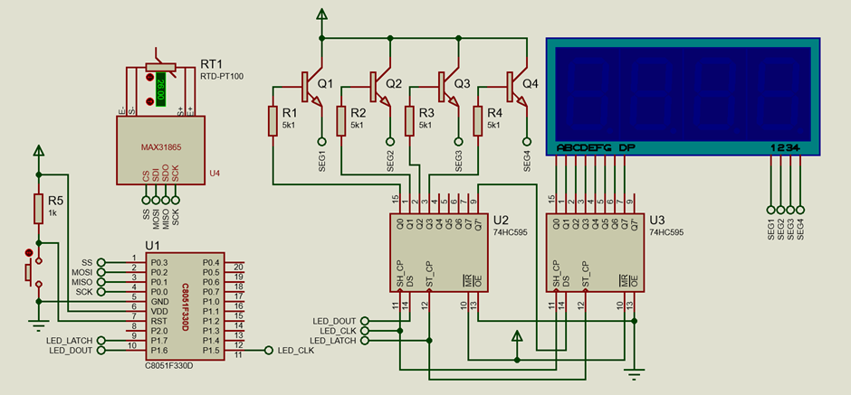
Explanation
MAX31865 is a PT100-to-digital converter. It converts resistance data from a PT100 RTD sensor to digital temperature data that is sent to a host microcontroller via an SPI bus.
Firstly, the system clock is set to 12.25MHz.
 void Oscillator_Init(void)
 {
     OSCICN = 0x82;
 }
Pins P0.0 to P0.3 are set as SPI pins in the crossbar.
 void Port_IO_Init(void)
 {
     // P0.0  -  SCK  (SPI0), Push-Pull,  Digital
     // P0.1  -  MISO (SPI0), Open-Drain, Digital
     // P0.2  -  MOSI (SPI0), Push-Pull,  Digital
     // P0.3  -  Skipped,     Push-Pull,  Digital
     // P0.4  -  Unassigned,  Open-Drain, Digital
     // P0.5  -  Unassigned,  Open-Drain, Digital
     // P0.6  -  Unassigned,  Open-Drain, Digital
     // P0.7  -  Unassigned,  Open-Drain, Digital

     // P1.0  -  Unassigned,  Open-Drain, Digital
     // P1.1  -  Unassigned,  Open-Drain, Digital
     // P1.2  -  Unassigned,  Open-Drain, Digital
     // P1.3  -  Unassigned,  Open-Drain, Digital
     // P1.4  -  Unassigned,  Open-Drain, Digital
     // P1.5  -  Skipped,     Push-Pull,  Digital
     // P1.6  -  Skipped,     Push-Pull,  Digital
     // P1.7  -  Skipped,     Push-Pull,  Digital

     P0MDOUT = 0x0D;
     P1MDOUT = 0xE0;
     P0SKIP = 0x08;
     P1SKIP = 0xE0;
     XBR0 = 0x02;
     XBR1 = 0x40;
 }
MAX31865 header file contains all the constants and function prototypes that would be eventually needed in the MAX31865 source file.
Now let’s look at what’s inside the source file. The first thing in the MAX31865 source file is the initialization of the MAX31865 along with the initialization of the SPI peripheral of the host C8051F330. The built-in SPI library of MikroC is used to do the peripheral hardware initialization.
 void MAX31865_init(void)
 {
     SPI1_Init_Advanced(1000000, _SPI_CLK_IDLE_LO | _SPI_CLK_ACTIVE_2_IDLE | _SPI_MASTER);
     delay_ms(10);

     MAX31865_CS = 1;

     MAX31865_write_byte(MAX31865_CONFIG_REG, \
                         MAX31865_CONFIG_BIAS | \
                         MAX31865_CONFIG_MODE_AUTO | \
                         MAX31865_CONFIG_3_WIRE | \
                         MAX31865_CONFIG_FAULT_STATUS | \
                         MAX31865_CONFIG_FILTER_50Hz);
 }
The SPI protocol defines four different modes of operation, also known as SPI bus modes. The modes differ in terms of the clock polarity and clock phase and the timing of the data signals. The four SPI bus modes are as follows:
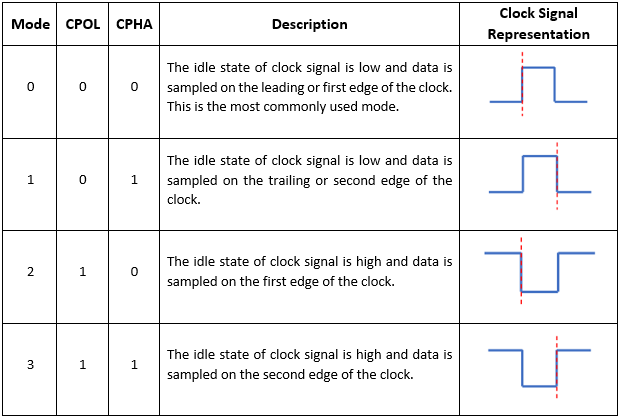
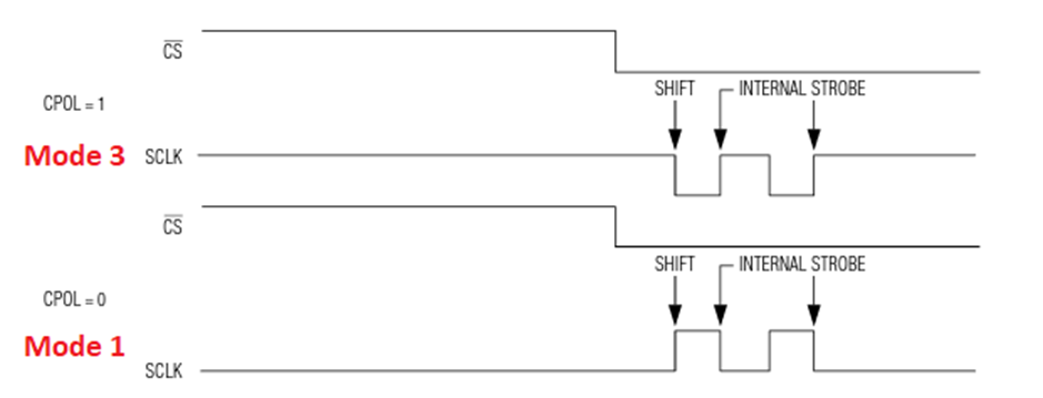
As per the datasheet of MAX31865, the chip supports both Mode 1 and Mode 3 SPI bus modes and so, here, Mode 1 is used.
The next important functions are the SPI byte read and write functions.
 void MAX31865_write_byte(unsigned char address, unsigned char value)
 {
     MAX31865_CS = 0;
     SPI_Write(address | 0x80);
     SPI_Write(value);
     MAX31865_CS = 1;
 }
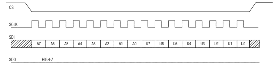
The write function is very simple. Writing to the chip is initiated by holding the chip/slave select pin low and sending the address and data bytes, i.e., two bytes are sent. Once the transaction is completed, the chip select pin is held high. During this process, no data reading is done. The polarity and phase of SPI signals are maintained automatically. The timing diagram for the SPI write is shown below and it clearly shows what has been described.
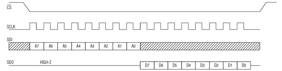
Reading the chip is similar to write process. The only difference that exists is the reading process itself. During an SPI bus read, a dummy byte is sent to the chip. The following function is for SPI byte read:
 unsigned char MAX31865_read_byte(unsigned char address)
 {
     unsigned char retval = 0x00;

     MAX31865_CS = 0;
     SPI_Write(address & 0x7F);
     retval = SPI_Read(0x00);
     MAX31865_CS = 1;

     return retval;
 }
The timing diagram for the SPI bus read matches the code given above.
The rest of the code is all about collecting and processing RTD data as per the datasheet.
Just like byte read and write, there are functions for word-sized read and write. These functions utilize the byte read and write functions.
 unsigned int MAX31865_read_word(unsigned char address)
 {
     unsigned char lb = 0x00;
     unsigned char hb = 0x00;
     unsigned int retval = 0x0000;

     hb = MAX31865_read_byte(address);
     lb = MAX31865_read_byte(address + 1);

     retval = hb;
     retval <<= 0x08;
     retval |= lb;

     return retval;
 }

 ....
 void MAX31865_write_word(unsigned char address, unsigned char lb, unsigned char hb)
 {
     MAX31865_write_byte(address, hb);
     MAX31865_write_byte((address + 1), lb);
 }
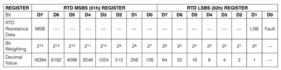
Going further, there is a function to read raw data from the RTD sensor.
 unsigned int MAX31865_get_RTD(void)
 {
   unsigned int rtd_value = 0x00;

   rtd_value = MAX31865_read_word(MAX31865_RTD_MSB_REG);
   rtd_value >>= 1;

   return rtd_value;
 }
As per the datasheet, the raw RTD data is 15-bits wide and so a word read operation is needed.
With the raw RTD data extracted, we can calculate RTD resistance and temperature after further data processing. This is done in the following function:
 signed int MAX31865_get_temperature(void)
 {
     float rt = 0.0;
     signed int t_value = 0;

     t_value = MAX31865_get_RTD();
     rt = (MAX31865_Reference_Resistance * t_value);
     rt /= 32768.0;

     rt /= MAX31865_RTD_Nominal_Value;
     rt = (rt - 1.0);
     t_value = (rt / MAX31865_RTD_A);

     return t_value;
 }
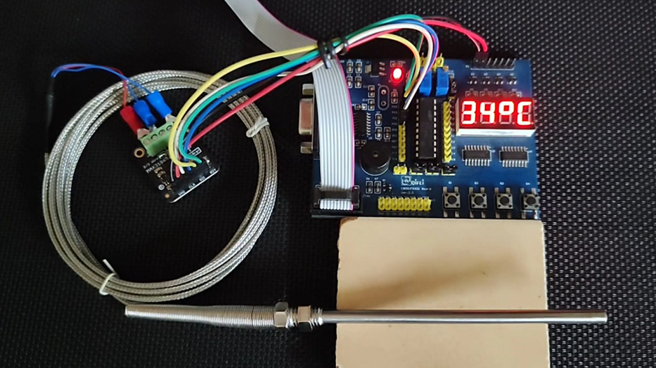
Inside the main, the temperature read by the chip is displayed on the on board seven-segment display.
 void main(void)
 {
     Init_Device();
     MAX31865_init();

     while(1)
     {
         value = MAX31865_get_temperature();
         delay_ms(600);
     };
 }
Demo
|
|
Thanks for the feedback….