Mastering the SiLabs C8051 Microcontroller
|
|
Watchdog Timer (WDT)
As anyone would expect in a microcontroller, C8051s pack watchdog timers for resetting them in the event of unexpected or unforeseen loop or software failure, leading to unwanted code execution halt.
Unlike most microcontrollers, however, there is no separate and dedicated watchdog timer in C8051F330D. The watchdog timer of C8051F330D is part of the Programmable Array Counter (PCA) hardware’s module 2 and so there are some advantages and disadvantages to this arrangement.
In terms of advantages, firstly no additional external hardware is needed and secondly, the implementation is not complex. The disadvantages are, dependency on the system clock for timing rather than a separate independent watchdog timer clock, loss of one PCA module if watchdog timer mode is used and difficulty in locating it in the datasheet.
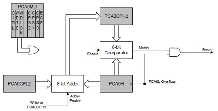
According to the block diagram shown below, the PCA watchdog timer works by using the compare-match principle. If a match occurs between PCA0CPH2 and PCA0H while the WDT is enabled, a reset will be generated. By default, the watchdog timer is enabled.
Code
 #define LED_DOUT          P1_6_bit
 #define LED_CLK           P1_5_bit
 #define LED_LATCH         P1_7_bit
 #define BUTTON            P1_4_bit

 unsigned char i = 0;
 register unsigned char val = 0;
 unsigned int value = 0;

 const unsigned char code segment_code[12] =
 {
   0xC0, // 0
   0xF9, // 1
   0xA4, // 2
   0xB0, // 3
   0x99, // 4
   0x92, // 5
   0x82, // 6
   0xF8, // 7
   0x80, // 8
   0x90, // 9
   0x7F, // .
   0xBF  // -
 };

 const unsigned char code display_pos[4] =
 {
   0xF7, //1st Display
   0xFB, //2nd Display
   0xFD, //3rd Display
   0xFE  //4th Display
 };

 void Init_Device(void);
 void write_74HC595(unsigned char send_data);
 void segment_write(unsigned char disp, unsigned char pos);

 void Timer_ISR()
 iv IVT_ADDR_ET3
 ilevel 0
 ics ICS_AUTO
 {
     switch(i)
     {
         case 0:
         {
             val = (value / 1000);
             break;
         }
         case 1:
         {
             val = ((value % 1000) / 100);
             break;
         }
         case 2:
         {
             val = ((value % 100) / 10);
             break;
         }
         case 3:
         {
             val = (value % 10);
             break;
         }
     }

     segment_write(val, i);

     i++;

     if(i > 3)
     {
        i = 0;
     }

     TMR3CN &= 0x7F;
 }

 void main(void)
 {
   signed int s = 200;

   Init_Device();

   while(1)
   {
       value++;
       delay_ms(20);
       if(BUTTON == 1)
       {
          PCA0CPH2 = 0;
          delay_ms(20);
          PCA0CPH2 = 0;
          delay_ms(20);
          PCA0CPH2 = 0;
       }
       else
       {
          PCA0CPH2 = 0;
          while(s > 0)
          {
              PCA0CPH2 = 0;
              delay_ms(30);
              s--;
          }
          while(1);
       }
   };
 }

 void PCA_Init()
 {
     PCA0MD &= ~0x40;
     PCA0MD = 0x00;
     PCA0CPM2 = 0x01;
     PCA0CPL2 = 0xFF;
     PCA0MD |= 0x40;
     PCA0CPH2 = 0;
 }

 void Timer_Init(void)
 {
     TMR3CN = 0x04;
     TMR3RLL = 0x02;
     TMR3RLH = 0xFC;
     PCA0CPH2 = 0;
 }

 void Port_IO_Init(void)
 {
     // P0.0  -  Unassigned,  Open-Drain, Digital
     // P0.1  -  Unassigned,  Open-Drain, Digital
     // P0.2  -  Unassigned,  Open-Drain, Digital
     // P0.3  -  Unassigned,  Open-Drain, Digital
     // P0.4  -  Unassigned,  Open-Drain, Digital
     // P0.5  -  Unassigned,  Open-Drain, Digital
     // P0.6  -  Unassigned,  Open-Drain, Digital
     // P0.7  -  Unassigned,  Open-Drain, Digital

     // P1.0  -  Unassigned,  Open-Drain, Digital
     // P1.1  -  Unassigned,  Open-Drain, Digital
     // P1.2  -  Unassigned,  Open-Drain, Digital
     // P1.3  -  Unassigned,  Open-Drain, Digital
     // P1.4  -  Skipped,     Open-Drain, Digital
     // P1.5  -  Skipped,     Push-Pull,  Digital
     // P1.6  -  Skipped,     Push-Pull,  Digital
     // P1.7  -  Skipped,     Push-Pull,  Digital

     P1MDOUT = 0xE0;
     P1SKIP = 0xF0;
     XBR1 = 0x40;
     PCA0CPH2 = 0;
 }

 void Oscillator_Init(void)
 {
     OSCICN = 0x82;
     PCA0CPH2 = 0;
 }

 void Interrupts_Init(void)
 {
     IE = 0x80;
     EIE1 = 0x80;
     PCA0CPH2 = 0;
 }

 void Init_Device(void)
 {
     PCA0MD = 0x00;

     Timer_Init();
     Port_IO_Init();
     Oscillator_Init();
     Interrupts_Init();
     PCA_Init();

     LED_LATCH = 1;
     LED_CLK = 1;
     LED_DOUT = 0;
     PCA0CPH2 = 0;
 }

 void write_74HC595(unsigned char send_data)
 {
     signed char clks = 8;

     while(clks > 0)
     {
         if((send_data & 0x80) == 0x00)
         {
           LED_DOUT = 0;
         }
         else
         {
           LED_DOUT = 1;
         }

         LED_CLK = 0;
         send_data <<= 1;
         clks--;
         LED_CLK = 1;
     }
 }

 void segment_write(unsigned char disp, unsigned char pos)
 {
     LED_LATCH = 0;
     write_74HC595(segment_code[disp]);
     write_74HC595(display_pos[pos]);
     LED_LATCH = 1;
 }
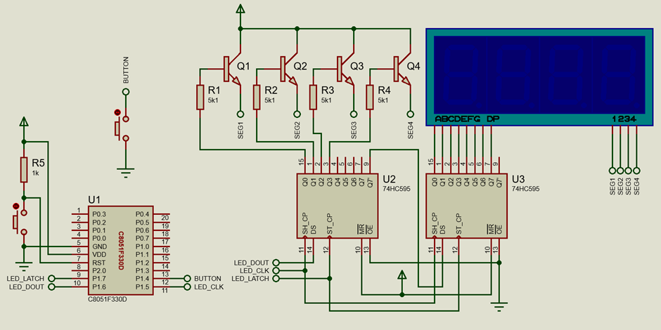
Schematic
Explanation
The following formula and table show some typical watchdog timeout values.
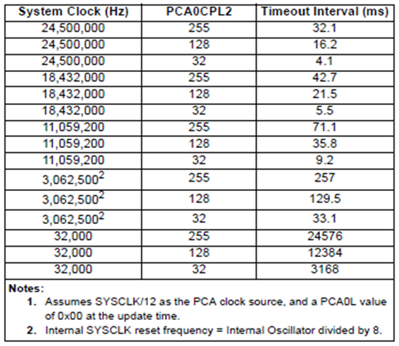

Thus with 24.5MHz internal oscillator, PCA0CPL2 = 255 and PCA0L = 0, the timeout is calculated as below:

The Config2 code configuration wizard can be used to generate necessary code automatically and we can avoid all of these calculations but it is better to know how things are done manually.
The setup for this example is just like all other examples covered so far. An onboard push button attached with pin P1.4 and the onboard seven-segment display are both used.
The PCA watchdog setup for the calculation shown above is shown below.
 void PCA_Init()
 {
     PCA0MD &= ~0x40;
     PCA0MD = 0x00;
     PCA0CPM2 = 0x01;
     PCA0CPL2 = 0xFF;
     PCA0MD |= 0x40;
     PCA0CPH2 = 0;
 }
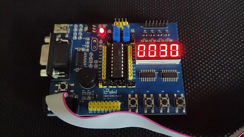
After start-up, the code begins incrementing a variable named value and its value is shown on the onboard seven-segment display.
 void main(void)
 {
   signed int s = 200;

   Init_Device();

   while(1)
   {
       value++;
       delay_ms(20);
       if(BUTTON == 1)
       {
          PCA0CPH2 = 0;
          delay_ms(20);
          PCA0CPH2 = 0;
          delay_ms(20);
          PCA0CPH2 = 0;
       }
       else
       {
          PCA0CPH2 = 0;
          while(s > 0)
          {
              PCA0CPH2 = 0;
              delay_ms(30);
              s--;
          }
          while(1);
       }
   };
 }
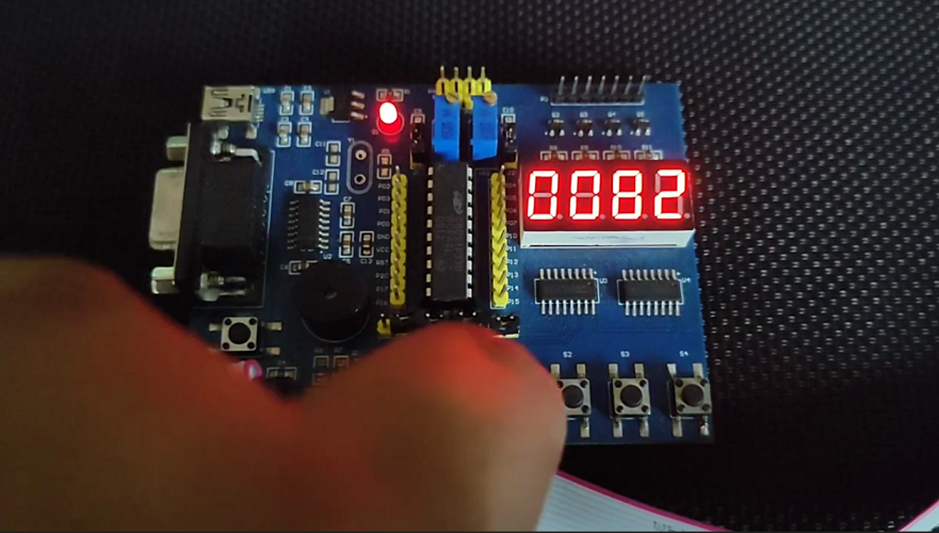
Unless the push button which is active-low by working principle is pressed, the variable keeps incrementing. Since the watchdog timer timeout is set to 32ms, the watchdog timer needs to be reset before this time expires and this is done by clearing the PCA0CPH2 register every 20ms. If the button is pressed, the code first enters a while loop that still resets the watchdog timer every 30ms without incrementing the variable value. This simulates an unforeseen software bug or stuck-like or hang-like condition. The code then enters into a jobless indefinite while loop. Since the PCA0CPH2 register is no longer cleared inside the jobless indefinite loop, it is gradually and internally increment until the timeout is reached. After the timeout period expires, the microcontroller is reset and the process repeats.
Demo
|
|
Thanks for the feedback….