Mastering the SiLabs C8051 Microcontroller
|
|
PCA in PWM Mode – Clover RGB LED Lights
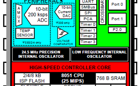
C8051s come with internal Programmable Counter Array (PCA) peripherals with different numbers of PCA I/O channels. PCA hardware can be used for waveform/signal input capture, high-speed frequency outputs, software timer, etc apart from PWM outputs.
The very basic thing that we can do with the internal PCA peripheral is Pulse-Width Modulation (PWM) generation. It needs no new mentioning that PWM is used in numerous applications like switch-mode power supplies, motor control, LED driving, etc.
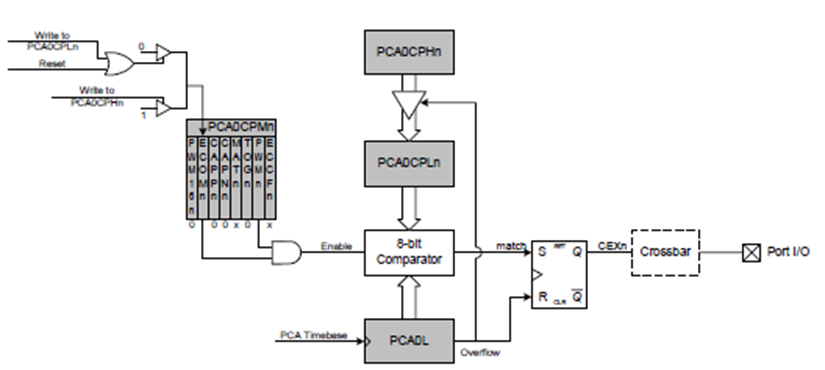
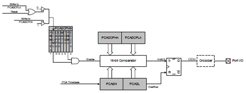
8 or 16-bit PWMs can be obtained from C8051s and they also offer many other advanced features that are typically needed in motor and power control applications. The following block diagrams show the PCA modules in 8- and 16-bit modes respectively. Both of these modes rely on the compare-match principle to achieve PWM generation.
Code
 const code unsigned int LUT_1[32] =
 {
       0,
       6423,
       12785,
       19023,
       25079,
       30892,
       36409,
       41574,
       46340,
       50659,
       54490,
       57796,
       60546,
       62713,
       64275,
       65219,
       65532,
       65219,
       64275,
       62713,
       60546,
       57796,
       54490,
       50659,
       46340,
       41574,
       36409,
       30892,
       25079,
       19023,
       12785,
       6423,
 };

 const code unsigned int LUT_2[32] =
 {
       54490,
       57796,
       60546,
       62713,
       64275,
       65219,
       65532,
       65219,
       64275,
       62713,
       60546,
       57796,
       54490,
       50659,
       46340,
       41574,
       36409,
       30892,
       25079,
       19023,
       12785,
       6423,
       0,
       6423,
       12785,
       19023,
       25079,
       30892,
       36409,
       41574,
       46340,
       50659
 };

 const code unsigned int LUT_3[32] =
 {
       60546,
       57796,
       54490,
       50659,
       46340,
       41574,
       36409,
       30892,
       25079,
       19023,
       12785,
       6423,
       0,
       6423,
       12785,
       19023,
       25079,
       30892,
       36409,
       41574,
       46340,
       50659,
       54490,
       57796,
       60546,
       62713,
       64275,
       65219,
       65532,
       65219,
       64275,
       62713
 };

 void PCA_Init(void);
 void Port_IO_Init(void);
 void Oscillator_Init(void);
 void Init_Device(void);
 void get_HB_LB(unsigned int value, unsigned char *HB, unsigned char *LB);
 void PWM_0_duty_cycle(unsigned int value);
 void PWM_1_duty_cycle(unsigned int value);
 void PWM_2_duty_cycle(unsigned int value);

 void main(void)
 {
     unsigned int i = 0;
     unsigned char j = 0;
     unsigned char mode = 1;

     Init_Device();

     while(1)
     {
         switch(mode)
         {
             case 1:
             {
                 PWM_1_duty_cycle(0);
                 PWM_2_duty_cycle(0);

                 for(j = 0; j < 6; j++)
                 {
                     for(i = 0; i < 32; i++)
                     {
                         PWM_0_duty_cycle(LUT_1[i]);
                         delay_ms(45);
                     }
                 }
                 break;
             }

             case 2:
             {
                 PWM_0_duty_cycle(0);
                 PWM_2_duty_cycle(0);

                 for(j = 0; j < 6; j++)
                 {
                     for(i = 0; i < 32; i++)
                     {
                         PWM_1_duty_cycle(LUT_1[i]);
                         delay_ms(45);
                     }
                 }
                 break;
             }

             case 3:
             {
                 PWM_0_duty_cycle(0);
                 PWM_1_duty_cycle(0);

                 for(j = 0; j < 6; j++)
                 {
                     for(i = 0; i < 32; i++)
                     {
                         PWM_2_duty_cycle(LUT_1[i]);
                         delay_ms(45);
                     }
                 }
                 break;
             }

             default:
             {
                 for(j = 0; j < 10; j++)
                 {
                     for(i = 0; i < 32; i++)
                     {
                         PWM_0_duty_cycle(LUT_1[i]);
                         PWM_1_duty_cycle(LUT_2[i]);
                         PWM_2_duty_cycle(LUT_3[i]);
                         delay_ms(200);
                     }
                 }
                 break;
             }
         }

         mode++;
         if(mode > 3)
         {
             mode  = 0;
         }
     };
 }

 void PCA_Init(void)
 {
     PCA0CN = 0x40;
     PCA0MD &= ~0x40;
     PCA0MD = 0x02;
     PCA0CPM0 = 0xC2;
     PCA0CPM1 = 0xC2;
     PCA0CPM2 = 0xC2;
     PCA0L = 0xC0;
     PCA0H = 0x4F;
     PCA0CPL0 = 0xFF;
     PCA0CPL1 = 0xFF;
     PCA0CPL2 = 0xFF;
     PCA0CPH0 = 0xFF;
     PCA0CPH1 = 0xFF;
     PCA0CPH2 = 0xFF;
 }

 void Port_IO_Init(void)
 {
     // P0.0  -  CEX0 (PCA),  Push-Pull,  Digital
     // P0.1  -  CEX1 (PCA),  Push-Pull,  Digital
     // P0.2  -  CEX2 (PCA),  Push-Pull,  Digital
     // P0.3  -  Unassigned,  Open-Drain, Digital
     // P0.4  -  Unassigned,  Open-Drain, Digital
     // P0.5  -  Unassigned,  Open-Drain, Digital
     // P0.6  -  Unassigned,  Open-Drain, Digital
     // P0.7  -  Unassigned,  Open-Drain, Digital

     // P1.0  -  Unassigned,  Open-Drain, Digital
     // P1.1  -  Unassigned,  Open-Drain, Digital
     // P1.2  -  Unassigned,  Open-Drain, Digital
     // P1.3  -  Unassigned,  Open-Drain, Digital
     // P1.4  -  Unassigned,  Open-Drain, Digital
     // P1.5  -  Unassigned,  Open-Drain, Digital
     // P1.6  -  Unassigned,  Open-Drain, Digital
     // P1.7  -  Unassigned,  Open-Drain, Digital

     P0MDOUT = 0x07;
     XBR1 = 0x43;
 }

 void Oscillator_Init(void)
 {
     OSCICN = 0x82;
 }

 void Init_Device(void)
 {
     PCA_Init();
     Port_IO_Init();
     Oscillator_Init();
 }

 void get_HB_LB(unsigned int value, unsigned char *HB, unsigned char *LB)
 {
     *LB = (unsigned char)(value & 0x00FF);
     *HB = (unsigned char)((value & 0xFF00) >> 0x08);
 }


 void PWM_0_duty_cycle(unsigned int value)
 {
     unsigned char hb = 0x00;
     unsigned char lb = 0x00;

     get_HB_LB(value, &hb, &lb);

     PCA0CPL0 = lb;
     PCA0CPH0 = hb;
     CCF0_bit = 0;
 }

 void PWM_1_duty_cycle(unsigned int value)
 {
     unsigned char hb = 0x00;
     unsigned char lb = 0x00;

     get_HB_LB(value, &hb, &lb);

     PCA0CPL1 = lb;
     PCA0CPH1 = hb;
     CCF1_bit = 0;
 }

 void PWM_2_duty_cycle(unsigned int value)
 {
     unsigned char hb = 0x00;
     unsigned char lb = 0x00;

     get_HB_LB(value, &hb, &lb);

     PCA0CPL2 = lb;
     PCA0CPH2 = hb;
     CCF2_bit = 0;
 }
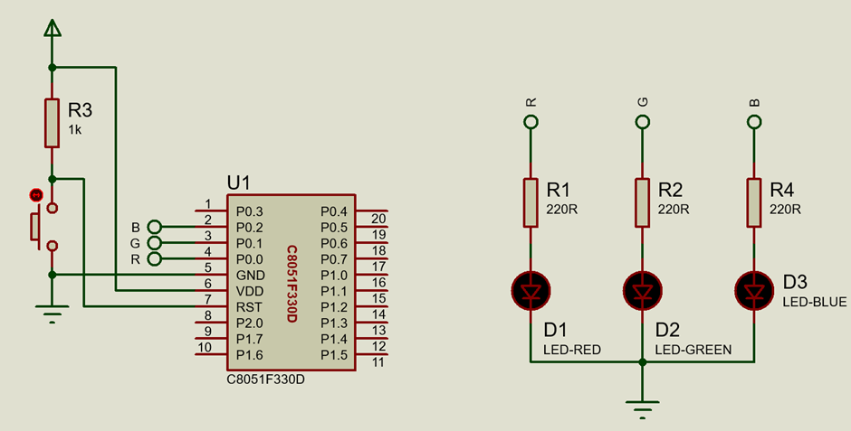
Schematic
Explanation
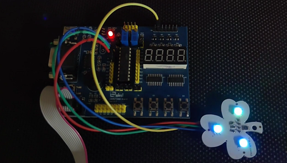
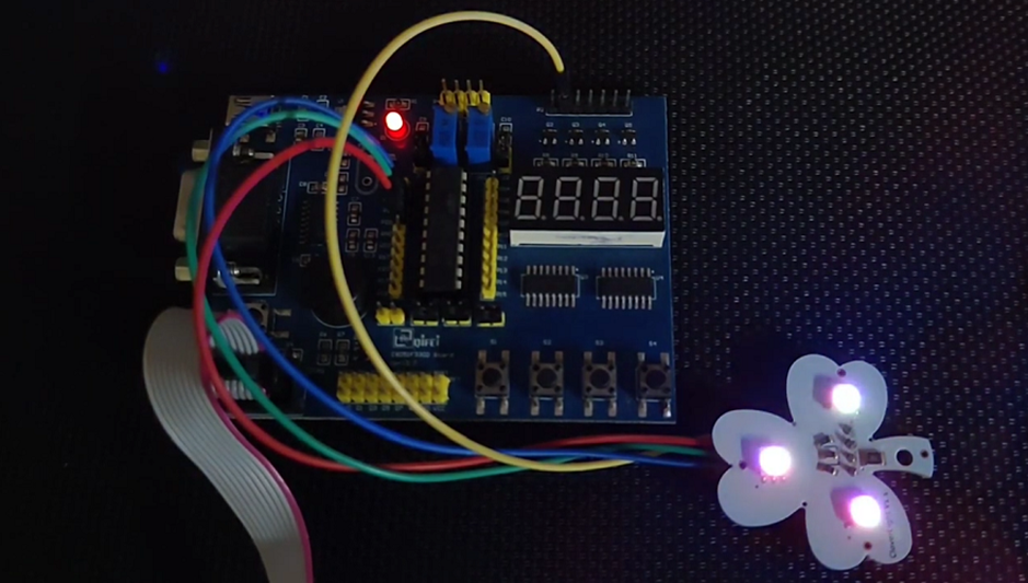
This demo uses multi-channel 16-bit PWMs to smoothly change the colours of three RGB LEDs. The LEDs are embedded in a leaf-like board from DFRobot called clover light. 8-bit PWM is functionally the same as 16-bit PWM. 8-bit PWM has a lower resolution but it can be used for high-frequency applications.
Red, Blue and Green colours from the LED are mixed in different ratios to form different colours. This mixing of colours is achieved using PWM and so all three PCA channels are used to drive the LEDs. Since PWM is output and not input, all of the PCA pins are set as digital push-pull outputs in the crossbar. PWM pins are labelled as CEXn pins.
 void Port_IO_Init(void)
 {
     // P0.0  -  CEX0 (PCA),  Push-Pull,  Digital
     // P0.1  -  CEX1 (PCA),  Push-Pull,  Digital
     // P0.2  -  CEX2 (PCA),  Push-Pull,  Digital
     // P0.3  -  Unassigned,  Open-Drain, Digital
     // P0.4  -  Unassigned,  Open-Drain, Digital
     // P0.5  -  Unassigned,  Open-Drain, Digital
     // P0.6  -  Unassigned,  Open-Drain, Digital
     // P0.7  -  Unassigned,  Open-Drain, Digital

     // P1.0  -  Unassigned,  Open-Drain, Digital
     // P1.1  -  Unassigned,  Open-Drain, Digital
     // P1.2  -  Unassigned,  Open-Drain, Digital
     // P1.3  -  Unassigned,  Open-Drain, Digital
     // P1.4  -  Unassigned,  Open-Drain, Digital
     // P1.5  -  Unassigned,  Open-Drain, Digital
     // P1.6  -  Unassigned,  Open-Drain, Digital
     // P1.7  -  Unassigned,  Open-Drain, Digital

     P0MDOUT = 0x07;
     XBR1 = 0x43;
 }
The system clock source is set to 12.5MHz and so one tick is 80ns.
 void Oscillator_Init(void)
 {
     OSCICN = 0x82;
 }
Timing is very important because PWM signals are timed outputs with variable pulse widths and so variable or unstable time bases would result in odd irregular waveforms.
A clock derived from the system clock or some other source is fed to the PCA peripheral and its counter keeps counting.
PWM is generated by comparing and matching the values of PCA0CPn and PCA0 registers. A PWM output pin is set when the contents of PCA0 counter match with the contents of PCA0CPn registers and it is reset when the contents of PCA0 counter overflow.
We can optionally load the PCA counter. This has no effect on PWM frequency but it does affect PWM duty cycle.
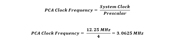
In this example, the PCA is set to generate three channel PWMs at approximately 46Hz. The PCA clock prescalar is set to 4 and so the 12.25MHz clock is scaled down as per the following calculation:
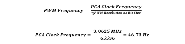
Since we are using 16-bit resolution PWM in this example, the PWM frequency is calculated as follows:
 void PCA_Init(void)
 {
     PCA0CN = 0x40;
     PCA0MD &= ~0x40;
     PCA0MD = 0x02;
     PCA0CPM0 = 0xC2;
     PCA0CPM1 = 0xC2;
     PCA0CPM2 = 0xC2;
     PCA0L = 0xC0;
     PCA0H = 0x4F;
     PCA0CPL0 = 0xFF;
     PCA0CPL1 = 0xFF;
     PCA0CPL2 = 0xFF;
     PCA0CPH0 = 0xFF;
     PCA0CPH1 = 0xFF;
     PCA0CPH2 = 0xFF;
 }
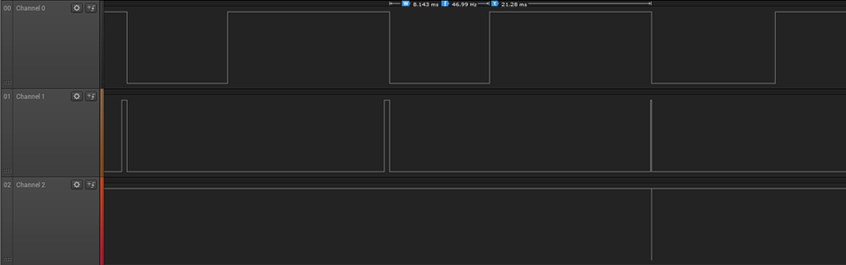
Note that the PCA counter is preloaded with a value and this is just to show that it has no effect on PWM frequency. The Saleae Logic analyser capture shown below shows the frequency of the three PWM waveforms.
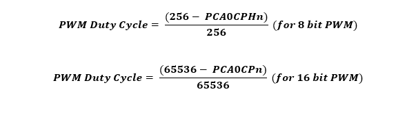
According to the datasheet PWM duty cycle for 8-bit and 16-bit PWMs are given as follows:
The following functions can be used to alter the duty cycles of respective PWM channels. These functions take 16-bit input and break the input into two bytes. These bytes are then loaded to respective PCA0CPLn and PCA0CPHn registers. PWM output is updated with the new values in PCA0CP registers upon clearing the capture-compare flag (CCFn).
 void PWM_0_duty_cycle(unsigned int value)
 {
     unsigned char hb = 0x00;
     unsigned char lb = 0x00;

     get_HB_LB(value, &hb, &lb);

     PCA0CPL0 = lb;
     PCA0CPH0 = hb;
     CCF0_bit = 0;
 }

 void PWM_1_duty_cycle(unsigned int value)
 {
     unsigned char hb = 0x00;
     unsigned char lb = 0x00;

     get_HB_LB(value, &hb, &lb);

     PCA0CPL1 = lb;
     PCA0CPH1 = hb;
     CCF1_bit = 0;
 }

 void PWM_2_duty_cycle(unsigned int value)
 {
     unsigned char hb = 0x00;
     unsigned char lb = 0x00;

     get_HB_LB(value, &hb, &lb);

     PCA0CPL2 = lb;
     PCA0CPH2 = hb;
     CCF2_bit = 0;
 }
Inside the main loop, all three PWM channels are driven using the data from respective lookup tables. These lookup tables contain sinusoidal PWM duty cycle values.
 void main(void)
 {
     unsigned int i = 0;
     unsigned char j = 0;
     unsigned char mode = 1;

     Init_Device();

     while(1)
     {
         switch(mode)
         {
             case 1:
             {
                 PWM_1_duty_cycle(0);
                 PWM_2_duty_cycle(0);

                 for(j = 0; j < 6; j++)
                 {
                     for(i = 0; i < 32; i++)
                     {
                         PWM_0_duty_cycle(LUT_1[i]);
                         delay_ms(45);
                     }
                 }
                 break;
             }

             case 2:
             {
                 PWM_0_duty_cycle(0);
                 PWM_2_duty_cycle(0);

                 for(j = 0; j < 6; j++)
                 {
                     for(i = 0; i < 32; i++)
                     {
                         PWM_1_duty_cycle(LUT_1[i]);
                         delay_ms(45);
                     }
                 }
                 break;
             }

             case 3:
             {
                 PWM_0_duty_cycle(0);
                 PWM_1_duty_cycle(0);

                 for(j = 0; j < 6; j++)
                 {
                     for(i = 0; i < 32; i++)
                     {
                         PWM_2_duty_cycle(LUT_1[i]);
                         delay_ms(45);
                     }
                 }
                 break;
             }

             default:
             {
                 for(j = 0; j < 10; j++)
                 {
                     for(i = 0; i < 32; i++)
                     {
                         PWM_0_duty_cycle(LUT_1[i]);
                         PWM_1_duty_cycle(LUT_2[i]);
                         PWM_2_duty_cycle(LUT_3[i]);
                         delay_ms(200);
                     }
                 }
                 break;
             }
         }

         mode++;
         if(mode > 3)
         {
             mode  = 0;
         }
     };
 }
Demo
|
|
Thanks for the feedback….