Mastering the SiLabs C8051 Microcontroller
|
|
Software PWM – Servo Motor Control
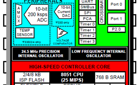
Sometimes we run out of PWM channels and in some cases, the PWM pins may have alternative use in a project. For a tiny microcontroller like the C8051F330D, both cases are very likely. In such scenarios, we can code software PWMs just like what we do with software-based communications like software-based I2C and software-based SPI. Any GPIO pin can be used for software PWM and that is the biggest advantage. There are a few limitations though with this concept. Firstly, some coding is needed and secondly, software PWM techniques are not fast and less accurate not to mention the limited options it offers, unlike hardware PWM.
Code
 #define LED_DOUT           P1_6_bit
 #define LED_CLK            P1_5_bit
 #define LED_LATCH          P1_7_bit

 #define INC_SW             P1_4_bit
 #define DEC_SW             P1_3_bit

 #define duty_min           5
 #define duty_max           25
 #define counts             240

 unsigned char i = 0;
 register unsigned char val = 0;
 unsigned char count = 0;
 unsigned char duty_cycle_1 = duty_min;
 unsigned char duty_cycle_2 = duty_max;

 const unsigned char code segment_code[12] =
 {
   0xC0, // 0
   0xF9, // 1
   0xA4, // 2
   0xB0, // 3
   0x99, // 4
   0x92, // 5
   0x82, // 6
   0xF8, // 7
   0x80, // 8
   0x90, // 9
   0x7F, // .
   0xBF  // -
 };

 const unsigned char code display_pos[4] =
 {
   0xF7, //1st Display
   0xFB, //2nd Display
   0xFD, //3rd Display
   0xFE  //4th Display
 };

 void PCA_Init(void);
 void Timer_Init(void);
 void Port_IO_Init(void);
 void Oscillator_Init(void);
 void Interrupts_Init(void);
 void Init_Device(void);
 void write_74HC595(unsigned char send_data);
 void segment_write(unsigned char disp, unsigned char pos);

 void Timer_2_ISR(void)
 iv IVT_ADDR_ET2
 ilevel 0
 ics ICS_AUTO
 {
     count++;

     if(count <= counts)
     {
         if(count <= duty_cycle_1)
         {
             P0_0_bit = 1;
         }
         else
         {
             P0_0_bit = 0;
         }

         if(count <= duty_cycle_2)
         {
             P0_1_bit = 1;
         }
         else
         {
             P0_1_bit = 0;
         }
     }

     else
     {
         count = 0;
     }
     P0_2_bit = ~P0_2_bit;
     TF2H_bit = 0;
 }

 void Timer_3_ISR(void)
 iv IVT_ADDR_ET3
 ilevel 1
 ics ICS_AUTO
 {
     switch(i)
     {
         case 0:
         {
             val = (duty_cycle_1 / 1000);
             break;
         }
         case 1:
         {
             val = ((duty_cycle_1 % 1000) / 100);
             break;
         }
         case 2:
         {
             val = ((duty_cycle_1 % 100) / 10);
             break;
         }
         case 3:
         {
             val = (duty_cycle_1 % 10);
             break;
         }
     }

     segment_write(val, i);

     i++;

     if(i > 3)
     {
        i = 0;
     }

     TMR3CN &= 0x7F;
 }

 void main(void)
 {
     Init_Device();

     while(1)
     {
         if(INC_SW == 0)
         {
             delay_ms(60);
             duty_cycle_1++;
             duty_cycle_2--;
         }

         if(DEC_SW == 0)
         {
             delay_ms(60);
             duty_cycle_1--;
             duty_cycle_2++;
         }

         if(duty_cycle_1 >= duty_max)
         {
             duty_cycle_1 = duty_max;
             duty_cycle_2 = duty_min;
         }

         if(duty_cycle_1 <= duty_min)
         {
             duty_cycle_1 = duty_min;
             duty_cycle_2 = duty_max;
         }
     };
 }

 void PCA_Init(void)
 {
     PCA0MD &= ~0x40;
     PCA0MD = 0x00;
 }

 void Timer_Init(void)
 {
     TMR2CN = 0x04;
     TMR2RLL = 0x99;
     TMR2RLH = 0xFF;
     TMR3CN = 0x04;
     TMR3RLL = 0x02;
     TMR3RLH = 0xFC;
 }

 void Port_IO_Init(void)
 {
     // P0.0  -  Skipped,     Push-Pull,  Digital
     // P0.1  -  Skipped,     Push-Pull,  Digital
     // P0.2  -  Skipped,     Push-Pull,  Digital
     // P0.3  -  Unassigned,  Open-Drain, Digital
     // P0.4  -  Unassigned,  Open-Drain, Digital
     // P0.5  -  Unassigned,  Open-Drain, Digital
     // P0.6  -  Unassigned,  Open-Drain, Digital
     // P0.7  -  Unassigned,  Open-Drain, Digital

     // P1.0  -  Unassigned,  Open-Drain, Digital
     // P1.1  -  Unassigned,  Open-Drain, Digital
     // P1.2  -  Unassigned,  Open-Drain, Digital
     // P1.3  -  Skipped,     Open-Drain, Digital
     // P1.4  -  Skipped,     Open-Drain, Digital
     // P1.5  -  Skipped,     Push-Pull,  Digital
     // P1.6  -  Skipped,     Push-Pull,  Digital
     // P1.7  -  Skipped,     Push-Pull,  Digital

     P0MDOUT = 0x07;
     P1MDOUT = 0xE0;
     P0SKIP = 0x07;
     P1SKIP = 0xF8;
     XBR1 = 0x40;
 }

 void Oscillator_Init(void)
 {
     OSCICN = 0x82;
 }

 void Interrupts_Init(void)
 {
     IE = 0xA0;
     EIE1 = 0x80;
 }

 void Init_Device(void)
 {
     PCA_Init();
     Timer_Init();
     Port_IO_Init();
     Oscillator_Init();
     Interrupts_Init();
 }

 void write_74HC595(unsigned char send_data)
 {
     signed char clks = 8;

     while(clks > 0)
     {
         if((send_data & 0x80) == 0x00)
         {
           LED_DOUT = 0;
         }
         else
         {
           LED_DOUT = 1;
         }

         LED_CLK = 0;
         send_data <<= 1;
         clks--;
         LED_CLK = 1;
     }
 }

 void segment_write(unsigned char disp, unsigned char pos)
 {
     LED_LATCH = 0;
     write_74HC595(segment_code[disp]);
     write_74HC595(display_pos[pos]);
     LED_LATCH = 1;
 }
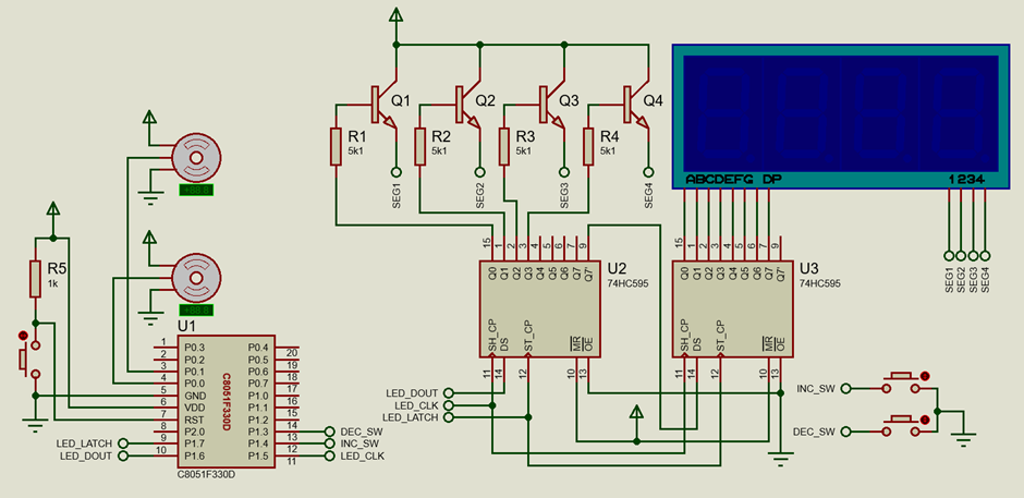
Schematic
Explanation
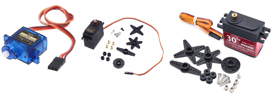
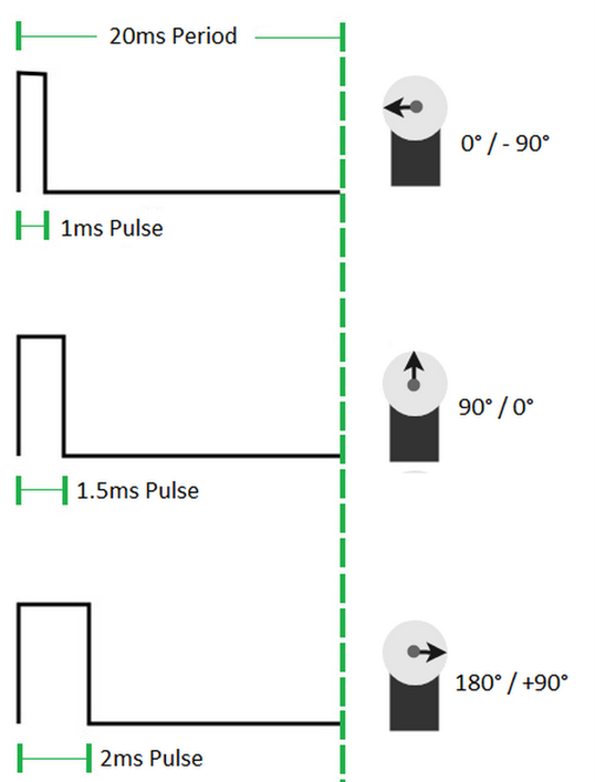
In this example, software PWM is used to drive two servo motors. Firstly, let us examine the servo motor signal timing diagram given below. From this diagram, it is evident that to drive a servo motor we need a PWM signal with a 20ms time period (50Hz) and 5 – 10% duty cycle.
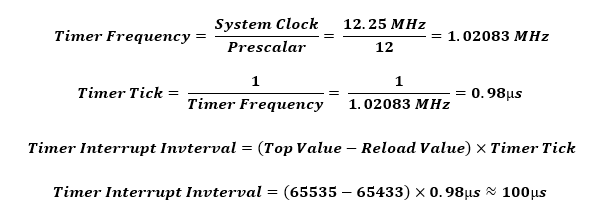
To code software PWM, all we need are GPIOs and a timer. Since a timer is needed, we have to be careful about the system clock setting. Here, the system clock is set to 12.25MHz, i.e., one system clock tick is about 80ns.
 void Timer_Init(void)
 {
     TMR2CN = 0x04;
     TMR2RLL = 0x99;
     TMR2RLH = 0xFF;
     TMR3CN = 0x04;
     TMR3RLL = 0x02;
     TMR3RLH = 0xFC;
 }


 void Interrupts_Init(void)
 {
     IE = 0xA0;
     EIE1 = 0x80;
 }
Inside the Timer 2 interrupt, a variable named count is incremented from 0 to 240. This variable defines the timer period. Since the variable resets after every 240 counts, the PWM period is calculated to be:

As stated, a servo motor is typically run using pulses having a 20ms time period and here we achieved just that, although not exactly 20ms. This difference is kept intentionally to balance off any tolerance in timing.
 #define duty_min           5
 #define duty_max           25
 #define counts             240

 ....

 void Timer_2_ISR(void)
 iv IVT_ADDR_ET2
 ilevel 0
 ics ICS_AUTO
 {
     count++;

     if(count <= counts)
     {
         if(count <= duty_cycle_1)
         {
             P0_0_bit = 1;
         }
         else
         {
             P0_0_bit = 0;
         }

         if(count <= duty_cycle_2)
         {
             P0_1_bit = 1;
         }
         else
         {
             P0_1_bit = 0;
         }
     }

     else
     {
         count = 0;
     }
     P0_2_bit = ~P0_2_bit;
     TF2H_bit = 0;
 }
Variables named duty_cycle_1 and duty_cycle_2 are used to control the duty cycles of two PWM channels. From 0 count to the value stored in these variables, respective GPIOs are set high and when the count variable exceeds these values, respective GPIOs are set low.
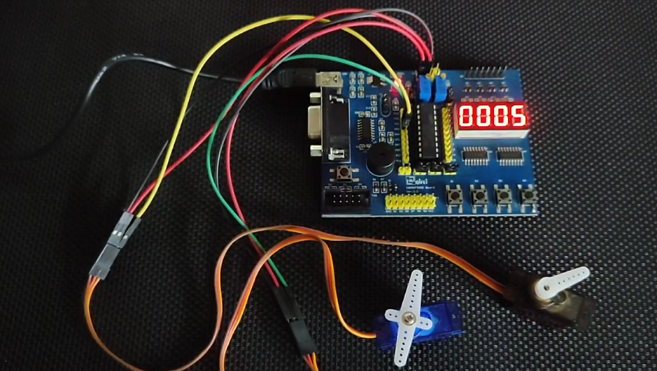
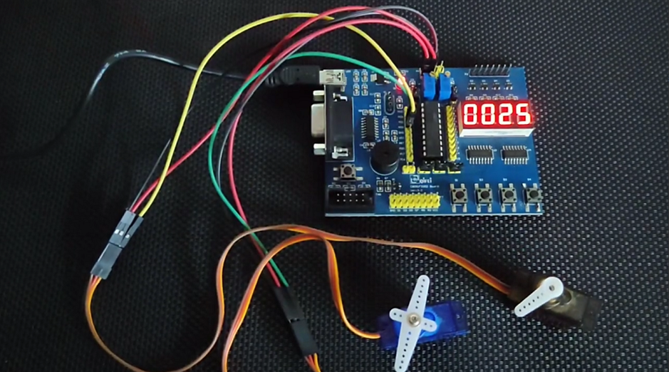
In the main, two onboard push buttons connected with pins P1.3 and P1.4 are pressed to change the duty cycle and the corresponding servo rotations are altered.
 void main(void)
 {
     Init_Device();

     while(1)
     {
         if(INC_SW == 0)
         {
             delay_ms(60);
             duty_cycle_1++;
             duty_cycle_2--;
         }

         if(DEC_SW == 0)
         {
             delay_ms(60);
             duty_cycle_1--;
             duty_cycle_2++;
         }

         if(duty_cycle_1 >= duty_max)
         {
             duty_cycle_1 = duty_max;
             duty_cycle_2 = duty_min;
         }

         if(duty_cycle_1 <= duty_min)
         {
             duty_cycle_1 = duty_min;
             duty_cycle_2 = duty_max;
         }
     };
 }
Demo
|
|
Thanks for the feedback….