Mastering the SiLabs C8051 Microcontroller
|
|
PCA in Frequency Output Mode – IR UART
In the early days of modern cell phones, sharing files between two cell phones was done using IrDA. There was no Wi-Fi or Bluetooth transfer available at that time. In many applications as such, short-range line-of-sight (LOS) wireless communication is needed and for cases, the infrared medium is the best solution and C8051s come with the right hardware for making IR transmitters because of the PCA peripheral’s ability to generate frequency outputs. Such outputs can be used to generate modulation or carrier waves which can then be mixed with data signals to make desired bursts of IR data.
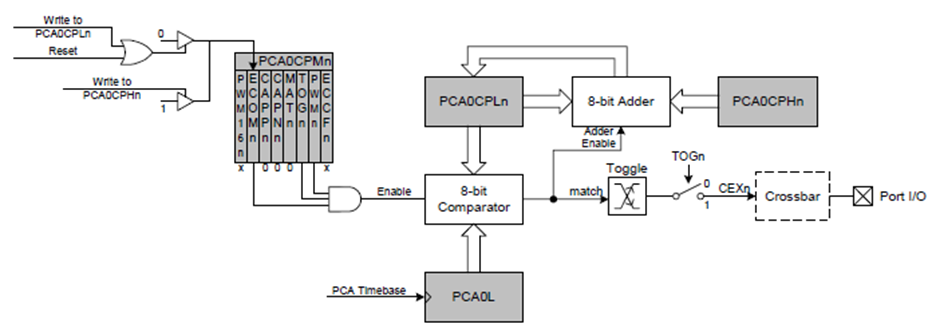
The block diagram below shows the PCA peripheral in frequency output mode and from this diagram, we can notice that the compare-match principle is used to achieve frequency output.
Code
IR TX main.c
 #define LED_DOUT   P1_6_bit
 #define LED_CLK    P1_5_bit
 #define LED_LATCH  P1_7_bit

 #define ADC_res    1023.0
 #define VDD_mv     3200.0

 #define freq       (6125000 / 2 /38000)

 unsigned char i = 0;
 register unsigned char val = 0;
 unsigned int value = 0;

 const unsigned char code segment_code[12] =
 {
   0xC0, // 0
   0xF9, // 1
   0xA4, // 2
   0xB0, // 3
   0x99, // 4
   0x92, // 5
   0x82, // 6
   0xF8, // 7
   0x80, // 8
   0x90, // 9
   0x9C, // degree
   0xC6  // C
 };

 const unsigned char code display_pos[4] =
 {
   0xF7, //1st Display
   0xFB, //2nd Display
   0xFD, //3rd Display
   0xFE  //4th Display
 };

 void PCA_Init(void);
 void Timer_Init(void);
 void UART_Init(void);
 void ADC_Init(void);
 void Voltage_Reference_Init(void);
 void Port_IO_Init(void);
 void Oscillator_Init(void);
 void Interrupts_Init(void);
 void Init_Device(void);
 void write_74HC595(unsigned char send_data);
 void segment_write(unsigned char disp, unsigned char pos);

 void Timer_ISR(void)
 iv IVT_ADDR_ET3
 ilevel 0
 ics ICS_AUTO
 {
     switch(i)
     {
         case 0:
         {
             val = (value / 10);
             break;
         }
         case 1:
         {
             val = (value % 10);
             break;
         }
         case 2:
         {
             val = 10;
             break;
         }
         case 3:
         {
             val = 11;
             break;
         }
     }

     segment_write(val, i);

     i++;

     if(i > 3)
     {
        i = 0;
     }

     TMR3CN &= 0x7F;
 }

 void main(void)
 {
     unsigned int t = 0;
     char tmp = 0;
     Init_Device();
     UART1_Init(1200);
     ADC1_Init_Advanced(_INTERNAL_REF | _RIGHT_ADJUSTMENT);

     while(1)
     {
         t = (ADC1_Get_Sample(16) * VDD_mv);
         t /= 1023.0;
         t = (((float)t - 776.0) / 2.86);
         value = t;
         tmp = t;
         UART1_Write(0xAA);
         UART1_Write((tmp / 10) + 0x30);
         UART1_Write((tmp % 10) + 0x30);
         delay_ms(400);
     };
 }

 void PCA_Init(void)
 {
     PCA0CN = 0x40;
     PCA0MD &= ~0x40;
     PCA0MD = 0x02;
     PCA0CPM1 = 0x46;
     PCA0CPH1 = 0x14;
 }

 void Timer_Init(void)
 {
     TMR3CN = 0x04;
     TMR3RLL = 0x01;
     TMR3RLH = 0xFE;
 }

 void UART_Init(void)
 {
     SCON0 = 0x10;
 }

 void ADC_Init(void)
 {
     AMX0P = 0x10;
     AMX0N = 0x11;
     ADC0CF = 0xF0;
     ADC0CN = 0x80;
 }

 void Voltage_Reference_Init(void)
 {
     REF0CN = 0x0F;
 }

 void Port_IO_Init(void)
 {
     // P0.0  -  CEX0 (PCA),  Open-Drain, Digital
     // P0.1  -  CEX1 (PCA),  Push-Pull,  Digital
     // P0.2  -  Unassigned,  Open-Drain, Digital
     // P0.3  -  Unassigned,  Open-Drain, Digital
     // P0.4  -  TX0 (UART0), Push-Pull,  Digital
     // P0.5  -  RX0 (UART0), Open-Drain, Digital
     // P0.6  -  Unassigned,  Open-Drain, Digital
     // P0.7  -  Unassigned,  Open-Drain, Digital

     // P1.0  -  Unassigned,  Open-Drain, Digital
     // P1.1  -  Unassigned,  Open-Drain, Digital
     // P1.2  -  Unassigned,  Open-Drain, Digital
     // P1.3  -  Unassigned,  Open-Drain, Digital
     // P1.4  -  Unassigned,  Open-Drain, Digital
     // P1.5  -  Skipped,     Push-Pull,  Digital
     // P1.6  -  Skipped,     Push-Pull,  Digital
     // P1.7  -  Skipped,     Push-Pull,  Digital

     P0MDOUT = 0x12;
     P1MDOUT = 0xE0;
     P1SKIP = 0xE0;
     XBR0 = 0x01;
     XBR1 = 0x42;
 }

 void Oscillator_Init(void)
 {
     OSCICN = 0x81;
 }

 void Interrupts_Init(void)
 {
     IE = 0x80;
     EIE1 = 0x80;
 }

 void Init_Device(void)
 {
     PCA_Init();
     Timer_Init();
     UART_Init();
     ADC_Init();
     Voltage_Reference_Init();
     Port_IO_Init();
     Oscillator_Init();
     Interrupts_Init();
 }

 void write_74HC595(unsigned char send_data)
 {
     signed char clks = 8;

     while(clks > 0)
     {
         if((send_data & 0x80) == 0x00)
         {
           LED_DOUT = 0;
         }
         else
         {
           LED_DOUT = 1;
         }

         LED_CLK = 0;
         send_data <<= 1;
         clks--;
         LED_CLK = 1;
     }
 }

 void segment_write(unsigned char disp, unsigned char pos)
 {
     LED_LATCH = 0;
     write_74HC595(segment_code[disp]);
     write_74HC595(display_pos[pos]);
     LED_LATCH = 1;
 }
IR RX main.c
 #define LED_DOUT          P1_6_bit
 #define LED_CLK           P1_5_bit
 #define LED_LATCH         P1_7_bit

 unsigned char i = 0;
 register unsigned char val = 0;
 unsigned int value = 0;
 unsigned char cnt = 0;

 unsigned char rx_buffer[3] = {0x00, 0x00, 0x00};

 const unsigned char code segment_code[12] =
 {
   0xC0, // 0
   0xF9, // 1
   0xA4, // 2
   0xB0, // 3
   0x99, // 4
   0x92, // 5
   0x82, // 6
   0xF8, // 7
   0x80, // 8
   0x90, // 9
   0x9C, // degree
   0xC6  // C
 };

 const unsigned char code display_pos[4] =
 {
   0xF7, //1st Display
   0xFB, //2nd Display
   0xFD, //3rd Display
   0xFE  //4th Display
 };

 void PCA_Init(void);
 void Timer_Init(void);
 void UART_Init(void);
 void Port_IO_Init(void);
 void Oscillator_Init(void);
 void Interrupts_Init(void);
 void Init_Device(void);
 void write_74HC595(unsigned char send_data);
 void segment_write(unsigned char disp, unsigned char pos);

 void UART0_ISR(void)
 iv IVT_ADDR_ES0
 ilevel 0
 ics ICS_AUTO
 {
     rx_buffer[cnt++] = UART_Read();
     RI0_bit = 0;
 }

 void Timer_ISR(void)
 iv IVT_ADDR_ET3
 ilevel 1
 ics ICS_AUTO
 {
     switch(i)
     {
         case 0:
         {
             val = (value / 10);
             break;
         }
         case 1:
         {
             val = (value % 10);
             break;
         }
         case 2:
         {
             val = 10;
             break;
         }
         case 3:
         {
             val = 11;
             break;
         }
     }

     segment_write(val, i);

     i++;

     if(i > 3)
     {
        i = 0;
     }

     TMR3CN &= 0x7F;
 }

 void main(void)
 {
     unsigned char tmp = 0x00;
     unsigned char temp = 0x00;

     Init_Device();
     UART1_Init(1200);

     while(1)
     {
         if(cnt >= 3)
         {
             if(rx_buffer[0] == 0xAA)
             {
                temp = (rx_buffer[1] - 0x30);
                tmp = (temp * 10);
                temp = (rx_buffer[2] - 0x30);
                tmp += temp;

                value = tmp;
             }
             cnt = 0;
         }
     };
 }

 void PCA_Init(void)
 {
     PCA0MD &= ~0x40;
     PCA0MD = 0x00;
 }

 void Timer_Init(void)
 {
     TMR3CN = 0x04;
     TMR3RLL = 0x02;
     TMR3RLH = 0xFC;
 }

 void UART_Init(void)
 {
     SCON0 = 0x10;
 }

 void Port_IO_Init(void)
 {
     // P0.0  -  Unassigned,  Open-Drain, Digital
     // P0.1  -  Unassigned,  Open-Drain, Digital
     // P0.2  -  Unassigned,  Open-Drain, Digital
     // P0.3  -  Unassigned,  Open-Drain, Digital
     // P0.4  -  TX0 (UART0), Push-Pull,  Digital
     // P0.5  -  RX0 (UART0), Open-Drain, Digital
     // P0.6  -  Unassigned,  Open-Drain, Digital
     // P0.7  -  Unassigned,  Open-Drain, Digital

     // P1.0  -  Unassigned,  Open-Drain, Digital
     // P1.1  -  Unassigned,  Open-Drain, Digital
     // P1.2  -  Unassigned,  Open-Drain, Digital
     // P1.3  -  Unassigned,  Open-Drain, Digital
     // P1.4  -  Unassigned,  Open-Drain, Digital
     // P1.5  -  Skipped,     Push-Pull,  Digital
     // P1.6  -  Skipped,     Push-Pull,  Digital
     // P1.7  -  Skipped,     Push-Pull,  Digital

     P0MDOUT = 0x10;
     P1MDOUT = 0xE0;
     P1SKIP = 0xE0;
     XBR0 = 0x01;
     XBR1 = 0x40;
 }

 void Oscillator_Init(void)
 {
     OSCICN = 0x82;
 }

 void Interrupts_Init(void)
 {
     IE = 0x90;
     EIE1 = 0x80;
 }

 void Init_Device(void)
 {
     PCA_Init();
     Timer_Init();
     UART_Init();
     Port_IO_Init();
     Oscillator_Init();
     Interrupts_Init();
 }

 void write_74HC595(unsigned char send_data)
 {
     signed char clks = 8;

     while(clks > 0)
     {
         if((send_data & 0x80) == 0x00)
         {
           LED_DOUT = 0;
         }
         else
         {
           LED_DOUT = 1;
         }

         LED_CLK = 0;
         send_data <<= 1;
         clks--;
         LED_CLK = 1;
     }
 }

 void segment_write(unsigned char disp, unsigned char pos)
 {
     LED_LATCH = 0;
     write_74HC595(segment_code[disp]);
     write_74HC595(display_pos[pos]);
     LED_LATCH = 1;
 }
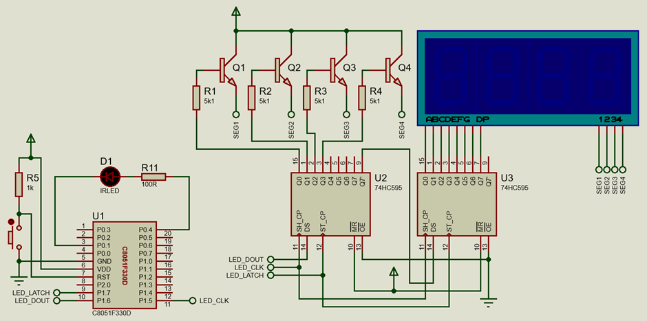
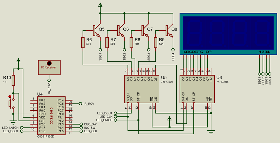
Schematic
IR TX
IR RX
Explanation
IR UART is simply ordinary slow-speed UART but over an infrared (IR) medium. It is slow in terms of the baud rate or the number of bits transferred per second. Higher baud rates are not suitable for wireless mediums. Only a pair of IR LED and IR receiver modules are needed.
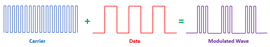
To transfer data over an IR medium we need a carrier wave and have it mixed with data to generate a modulated wave that is receivable by the IR receiver module. The idea is rudimentarily shown in the drawing below:
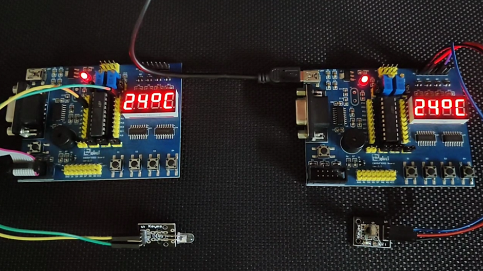
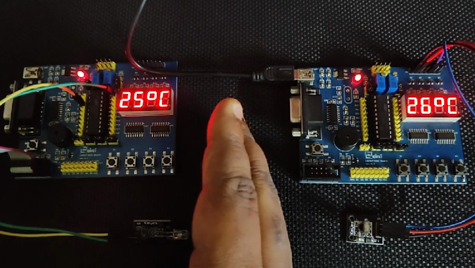
Like the RF module example, two C8051F330D boards are used in this example. One of these two is an IR transmitter while the other is an IR receiver. The transmitter is responsible for showing and transmitting its internal temperature data while the receiver is responsible for showing this data on its onboard seven-segment displays.
First, let’s see the transmitter side coding. The transmitter uses an IR LED to transmit data via an IR medium. The IRLED anode and cathode pins are connected to the TXD (P0.4) and PCA CEX1 (P0.1) pins respectively. Connecting the IR LED this way automatically ensures modulation. The TXD pin is responsible for sending data while the PCA pin ensures transmission of carrier wave.
 void Port_IO_Init(void)
 {
     // P0.1  -  CEX1 (PCA),  Push-Pull,  Digital
     // P0.4  -  TX0 (UART0), Push-Pull,  Digital

     // P1.5  -  Skipped,     Push-Pull,  Digital
     // P1.6  -  Skipped,     Push-Pull,  Digital
     // P1.7  -  Skipped,     Push-Pull,  Digital

     P0MDOUT = 0x12;
     P1MDOUT = 0xE0;
     P1SKIP = 0xE0;
     XBR0 = 0x01;
     XBR1 = 0x42;
 }
The system clock is set to 6.125MHz by scaling the internal oscillator.
 void Oscillator_Init(void)
 {
     OSCICN = 0x81;
 }
Let us now see the settings that have let us output 38kHz carrier wave from the PCA module. According to the device datasheet, the following formula should be used to generate frequency output:

According to the settings, the PCA clock has a frequency of:

and the frequency output from the PCA channel is calculated to be:

This ensures the required 38KHz carrier wave.
 void PCA_Init(void)
 {
     PCA0CN = 0x40;
     PCA0MD &= ~0x40;
     PCA0MD = 0x02;
     PCA0CPM1 = 0x46;
     PCA0CPH1 = 0x14;
 }
The PCA interrupts are not needed and are optional.
All that is left at this stage on the transmitter side is the main code. Here, we can see that the UART is set with a 1200 baud rate using MikroC’s built-in UART library. The communication speed is slow but it is set so because of a trade-off between speed and reliability.
 void main(void)
 {
     unsigned int t = 0;
     char tmp = 0;

     Init_Device();
     UART1_Init(1200);
     ADC1_Init_Advanced(_INTERNAL_REF | _RIGHT_ADJUSTMENT);

     while(1)
     {
         t = (ADC1_Get_Sample(16) * VDD_mv);
         t /= 1023.0;
         t = (((float)t - 776.0) / 2.86);

         value = t;
         tmp = t;

         UART1_Write(0xAA);
         UART1_Write((tmp / 10) + 0x30);
         UART1_Write((tmp % 10) + 0x30);
         delay_ms(400);
     };
 }
Note that, here, the internal temperature sensor is used as a source of data to be transmitted. The main loop reads this sensor, displays the temperature and sends the temperature to the C8051F330D board nearby.
To be able to use the internal temperature sensor (ADC channel 16), we need to use the internal reference. The following graph shows the relation between the output voltage from the sensor and temperature.
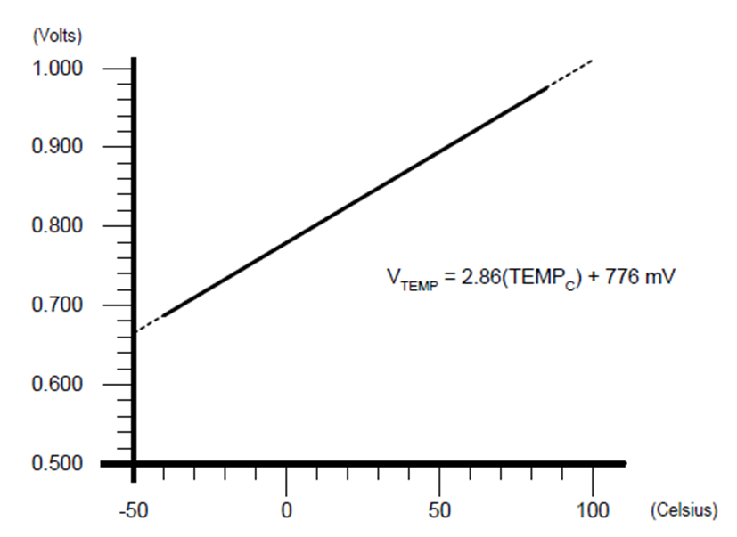
The equation in this graph gives voltage as a function of temperature. However, we need temperature data from voltage since we can measure voltage from ADC and certainly not temperature directly. Thus, the equation above needs rearrangement.
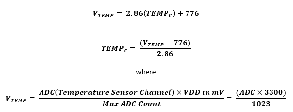
These have been used inside the main loop.
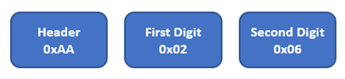
Lastly, temperature data is sent using UART in the following packet format:
The code for the receiver side is very easy because the IR receiver module internally completes the demodulation task and provide raw UART output.
Firstly, data received by the UART is received using the interrupt method. Received serial data are stored in an array buffer called rx_buffer.
 void UART0_ISR(void)
 iv IVT_ADDR_ES0
 ilevel 0
 ics ICS_AUTO
 {
     rx_buffer[cnt++] = UART_Read();
     RI0_bit = 0;
 }
Since three bytes of data are to be received, the main code waits for three-byte counts before processing the received data. Firstly, the preamble header is looked for. If the first byte matches with the expected header (0xAA) then the next two bytes are assumed to contain temperature data. After extracting the bytes, the temperature data received is shown on the onboard seven-segment display.
 void main(void)
 {
     unsigned char tmp = 0x00;
     unsigned char temp = 0x00;

     Init_Device();
     UART1_Init(1200);

     while(1)
     {
         if(cnt >= 3)
         {
             if(rx_buffer[0] == 0xAA)
             {
                temp = (rx_buffer[1] - 0x30);
                tmp = (temp * 10);
                temp = (rx_buffer[2] - 0x30);
                tmp += temp;

                value = tmp;
             }
             cnt = 0;
         }
     };
 }
Demo
|
|
Thanks for the feedback….