Mastering the SiLabs C8051 Microcontroller
|
|
Bit-Banging – RF Communication with RF Modules
In many situations, we need to create our communication protocol and in those cases bit-banging I/O pins are the only method we have to resort to. On the other hand, there is no other better way other than bit-banging to reliably transmit-receive data between low-cost 315/433 MHz RF modules. Using UART is an alternative but some microcontrollers lack these hardware peripherals while in other cases, it may have other uses. Another important thing to note is the fact that RF modules of these frequency ranges pickup lot of background RF noise and so there is no simple technique to reliably transmit and receive valid data. Thus, we need some sort of data encapsulation.
Code
RF TX main.c
 #define LED_DOUT           P1_6_bit
 #define LED_CLK            P1_5_bit
 #define LED_LATCH          P1_7_bit

 #define INC_SW             P1_4_bit
 #define DEC_SW             P1_3_bit

 #define RF_RX              P0_0_bit
 #define RF_TX              P0_1_bit

 void PCA_Init(void);
 void Timer_Init(void);
 void Port_IO_Init(void);
 void Oscillator_Init(void);
 void Interrupts_Init(void);
 void Init_Device(void);
 void write_74HC595(unsigned char send_data);
 void segment_write(unsigned char disp, unsigned char pos);
 void send_data(unsigned char value);
 void RF_send(unsigned char rf_data);

 unsigned char i = 0;
 unsigned char val = 0;
 signed int value = 0;

 const unsigned char code segment_code[12] =
 {
   0xC0, // 0
   0xF9, // 1
   0xA4, // 2
   0xB0, // 3
   0x99, // 4
   0x92, // 5
   0x82, // 6
   0xF8, // 7
   0x80, // 8
   0x90, // 9
   0x7F, // .
   0xBF  // -
 };

 const unsigned char code display_pos[4] =
 {
   0xF7, //1st Display
   0xFB, //2nd Display
   0xFD, //3rd Display
   0xFE  //4th Display
 };

 void Timer_3_ISR(void)
 iv IVT_ADDR_ET3
 ilevel 0
 ics ICS_AUTO
 {
     switch(i)
     {
         case 0:
         {
             val = (value / 1000);
             break;
         }
         case 1:
         {
             val = ((value % 1000) / 100);
             break;
         }
         case 2:
         {
             val = ((value % 100) / 10);
             break;
         }
         case 3:
         {
             val = (value % 10);
             break;
         }
     }

     segment_write(val, i);

     i++;

     if(i > 3)
     {
        i = 0;
     }

     TMR3CN &= 0x7F;
 }

 void main(void)
 {
     Init_Device();

     while(1)
     {
         if(INC_SW == 0)
         {
             delay_ms(40);
             value++;
         }

         if(DEC_SW == 0)
         {
             delay_ms(40);
             value--;
         }

         if(value > 200)
         {
             value = 0;
         }

         if(value < 0)
         {
             value = 99;
         }

         send_data(value);
         delay_ms(100);
     };
 }

 void PCA_Init(void)
 {
     PCA0MD &= ~0x40;
     PCA0MD = 0x00;
 }

 void Timer_Init(void)
 {
     TMR3CN = 0x04;
     TMR3RLL = 0x02;
     TMR3RLH = 0xFC;
 }

 void Port_IO_Init(void)
 {
     // P0.0  -  Skipped,     Open-Drain, Digital
     // P0.1  -  Skipped,     Push-Pull,  Digital
     // P0.2  -  Unassigned,  Open-Drain, Digital
     // P0.3  -  Unassigned,  Open-Drain, Digital
     // P0.4  -  Unassigned,  Open-Drain, Digital
     // P0.5  -  Unassigned,  Open-Drain, Digital
     // P0.6  -  Unassigned,  Open-Drain, Digital
     // P0.7  -  Unassigned,  Open-Drain, Digital

     // P1.0  -  Unassigned,  Open-Drain, Digital
     // P1.1  -  Unassigned,  Open-Drain, Digital
     // P1.2  -  Unassigned,  Open-Drain, Digital
     // P1.3  -  Unassigned,  Open-Drain, Digital
     // P1.4  -  Unassigned,  Open-Drain, Digital
     // P1.5  -  Skipped,     Push-Pull,  Digital
     // P1.6  -  Skipped,     Push-Pull,  Digital
     // P1.7  -  Skipped,     Push-Pull,  Digital

     P0MDOUT = 0x02;
     P1MDOUT = 0xE0;
     P0SKIP = 0x03;
     P1SKIP = 0xE0;
     XBR1 = 0x40;
 }

 void Oscillator_Init(void)
 {
     OSCICN = 0x82;
 }

 void Interrupts_Init(void)
 {
     IE = 0x80;
     EIE1 = 0x80;
 }

 void Init_Device(void)
 {
     PCA_Init();
     Timer_Init();
     Port_IO_Init();
     Oscillator_Init();
     Interrupts_Init();
 }

 void write_74HC595(unsigned char send_data)
 {
     signed char clks = 8;

     while(clks > 0)
     {
         if((send_data & 0x80) == 0x00)
         {
           LED_DOUT = 0;
         }
         else
         {
           LED_DOUT = 1;
         }

         LED_CLK = 0;
         send_data <<= 1;
         clks--;
         LED_CLK = 1;
     }
 }

 void segment_write(unsigned char disp, unsigned char pos)
 {
     write_74HC595(segment_code[disp]);
     write_74HC595(display_pos[pos]);
     LED_LATCH = 0;
     LED_LATCH = 1;
 }

 void send_data(unsigned char value)
 {
      signed char s = 20;
      unsigned char CRC = 0;

      CRC = (value & 0xAA);

      while(s > 0x00)
      {
            RF_TX = 1;
            delay_us(500);
            RF_TX = 0;
            delay_us(500);
            s--;
      }
      delay_us(100);

      RF_send(value);
      RF_send(CRC);
 }

 void RF_send(unsigned char rf_data)
 {
     signed char s = 0x08;

     while(s > 0x00)
     {
          RF_TX = 1;

          if(rf_data & 0x80)
          {
              delay_ms(2);
          }
          else
          {
              delay_ms(1);
          }

          RF_TX = 0;
          delay_ms(1);
          rf_data <<= 1;
          s--;
     }
 }
RF RX main.c
 #define LED_DOUT           P1_6_bit
 #define LED_CLK            P1_5_bit
 #define LED_LATCH          P1_7_bit

 #define RF_RX              P0_0_bit
 #define RF_TX              P0_1_bit

 #define sync               0x09
 #define error              0x06

 void PCA_Init(void);
 void Timer_Init(void);
 void Port_IO_Init(void);
 void Oscillator_Init(void);
 void Interrupts_Init(void);
 void Init_Device(void);
 void write_74HC595(unsigned char send_data);
 void segment_write(unsigned char disp, unsigned char pos);
 unsigned char receive_data(void);
 signed long decode_data(void);

 unsigned char i = 0;
 unsigned char val = 0;
 signed int value = 0;

 const unsigned char code segment_code[12] =
 {
   0xC0, // 0
   0xF9, // 1
   0xA4, // 2
   0xB0, // 3
   0x99, // 4
   0x92, // 5
   0x82, // 6
   0xF8, // 7
   0x80, // 8
   0x90, // 9
   0x7F, // .
   0xBF  // -
 };

 const unsigned char code display_pos[4] =
 {
   0xF7, //1st Display
   0xFB, //2nd Display
   0xFD, //3rd Display
   0xFE  //4th Display
 };

 void Timer_3_ISR(void)
 iv IVT_ADDR_ET3
 ilevel 0
 ics ICS_AUTO
 {
     switch(i)
     {
         case 0:
         {
             val = (value / 1000);
             break;
         }
         case 1:
         {
             val = ((value % 1000) / 100);
             break;
         }
         case 2:
         {
             val = ((value % 100) / 10);
             break;
         }
         case 3:
         {
             val = (value % 10);
             break;
         }
     }

     segment_write(val, i);

     i++;

     if(i > 3)
     {
        i = 0;
     }

     TMR3CN &= 0x7F;
 }

 void main(void)
 {
     Init_Device();

     while(1)
     {
         value = decode_data();
     };
 }

 void PCA_Init(void)
 {
     PCA0MD &= ~0x40;
     PCA0MD = 0x00;
 }

 void Timer_Init(void)
 {
     TMR3CN = 0x04;
     TMR3RLL = 0x02;
     TMR3RLH = 0xFC;
 }

 void Port_IO_Init(void)
 {
     // P0.0  -  Skipped,     Open-Drain, Digital
     // P0.1  -  Skipped,     Push-Pull,  Digital
     // P0.2  -  Unassigned,  Open-Drain, Digital
     // P0.3  -  Unassigned,  Open-Drain, Digital
     // P0.4  -  Unassigned,  Open-Drain, Digital
     // P0.5  -  Unassigned,  Open-Drain, Digital
     // P0.6  -  Unassigned,  Open-Drain, Digital
     // P0.7  -  Unassigned,  Open-Drain, Digital

     // P1.0  -  Unassigned,  Open-Drain, Digital
     // P1.1  -  Unassigned,  Open-Drain, Digital
     // P1.2  -  Unassigned,  Open-Drain, Digital
     // P1.3  -  Unassigned,  Open-Drain, Digital
     // P1.4  -  Unassigned,  Open-Drain, Digital
     // P1.5  -  Skipped,     Push-Pull,  Digital
     // P1.6  -  Skipped,     Push-Pull,  Digital
     // P1.7  -  Skipped,     Push-Pull,  Digital

     P0MDOUT = 0x02;
     P1MDOUT = 0xE0;
     P0SKIP = 0x03;
     P1SKIP = 0xE0;
     XBR1 = 0x40;
 }

 void Oscillator_Init(void)
 {
     OSCICN = 0x82;
 }

 void Interrupts_Init(void)
 {
     IE = 0x80;
     EIE1 = 0x80;
 }

 void Init_Device(void)
 {
     PCA_Init();
     Timer_Init();
     Port_IO_Init();
     Oscillator_Init();
     Interrupts_Init();
 }

 void write_74HC595(unsigned char send_data)
 {
     signed char clks = 8;

     while(clks > 0)
     {
         if((send_data & 0x80) == 0x00)
         {
           LED_DOUT = 0;
         }
         else
         {
           LED_DOUT = 1;
         }

         LED_CLK = 0;
         send_data <<= 1;
         clks--;
         LED_CLK = 1;
     }
 }

 void segment_write(unsigned char disp, unsigned char pos)
 {
     write_74HC595(segment_code[disp]);
     write_74HC595(display_pos[pos]);
     LED_LATCH = 0;
     LED_LATCH = 1;
 }

 unsigned char receive_data(void)
 {
     unsigned char t = 0;

     while(!RF_RX);
     while(RF_RX)
     {
         t++;
         delay_us(10);
     };

     if((t > 25) && (t < 75))
     {
         return sync;
     }
     else if((t > 175) && (t < 225))
     {
         return 1;
     }
     else if((t > 75) && (t < 125))
     {
         return 0;
     }
     else
     {
         return error;
     }
 }

 signed long decode_data(void)
 {
     unsigned char d = 0;
     unsigned char s = 0;
     unsigned long value = 0;
     unsigned char v1 = 0;
     unsigned char v2 = 0;

     while(receive_data() != sync);

     d = receive_data();
     while(d == sync)
     {
          d = receive_data();
     };

     while(s < 15)
     {
         switch(d)
         {
             case 1:
             {
                 value |= 1;
                 break;
             }
             case 0:
             {
                 break;
             }
             case sync:
             case error:
             {
                 return -1;
             }
         }
         s++;
         value <<= 1;
         d = receive_data();
     }

     v1 = (value >> 8);
     v2 = (value & 0x00FF);
     delay_ms(4);

     if((v1 & 0xAA) == v2)
     {
         return v1;
     }
     else
     {
         return -1;
     }
 }
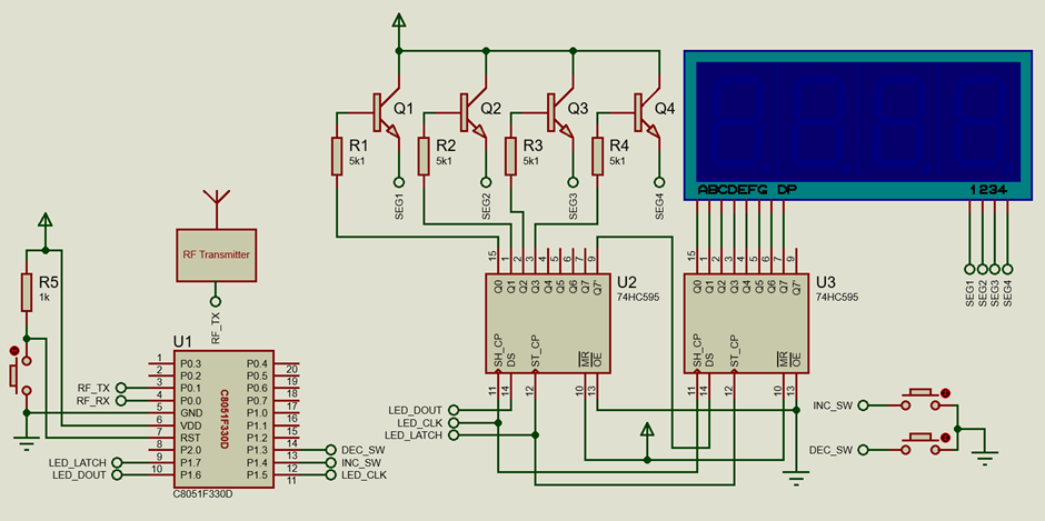
Schematic
RF TX
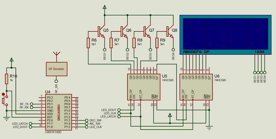
RF RX
Explanation
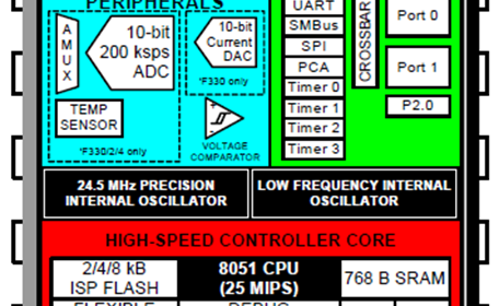
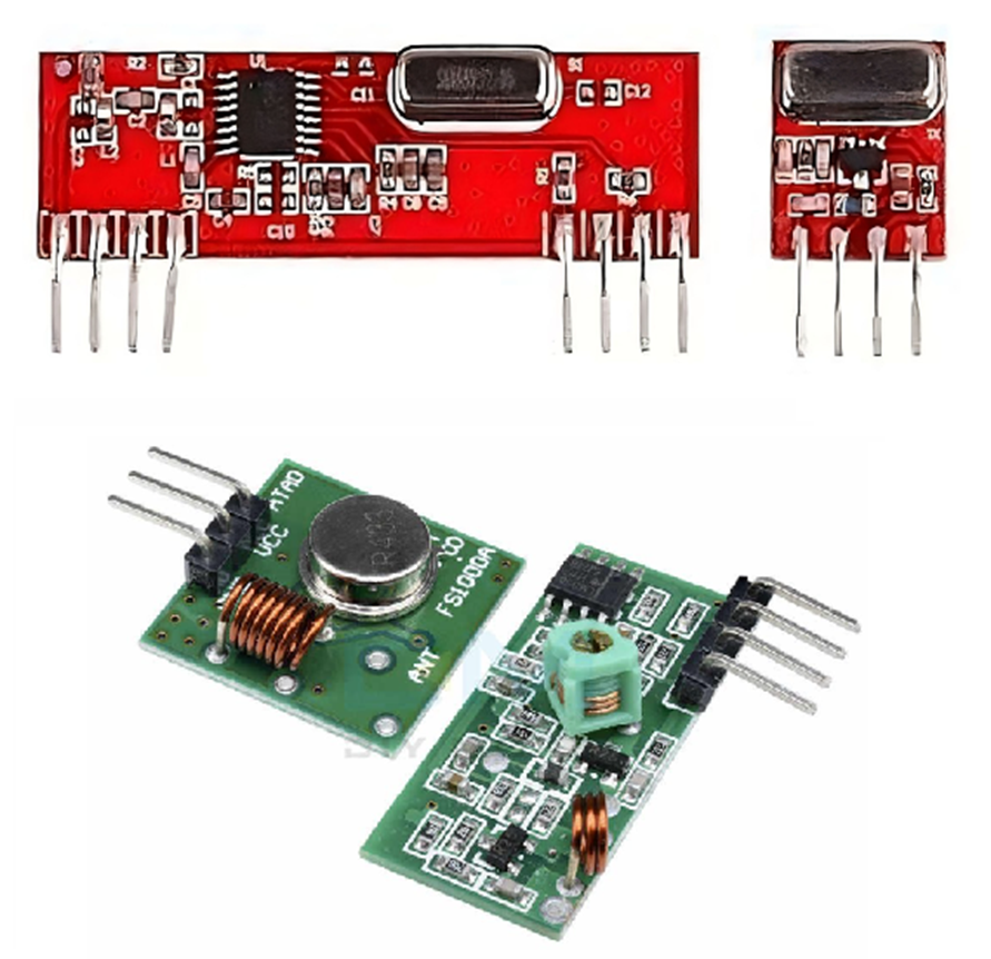
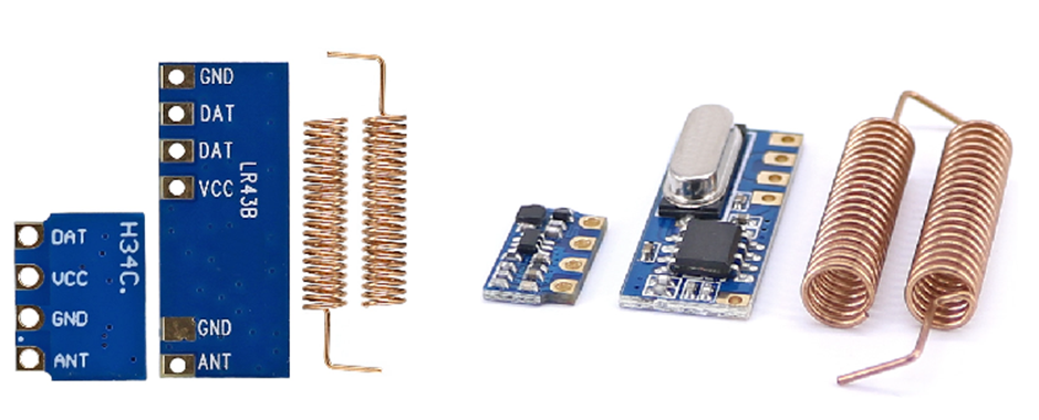
RF modules usually come in pairs – a transmitter and a receiver. P0.0 and P0.1 are RF TX and RF RX pins respectively. These pins are bit-banged. Two C8051F330D microcontroller boards have been used in this example – one is a transmitter and the other is a receiver. The modules used in this example are similar to the ones shown below although any other RF module of similar nature would work fine. I have tested this example with various other RF modules including 315 MHz ones without any issues.
The bit-banging technique employed here is based on the time-slotting technique similar to DS18B20 digital temperature sensor. Ones and zeroes are defined by pulse widths. There is no additional hardware peripheral needed apart from I/O pins to achieve bit-banging.
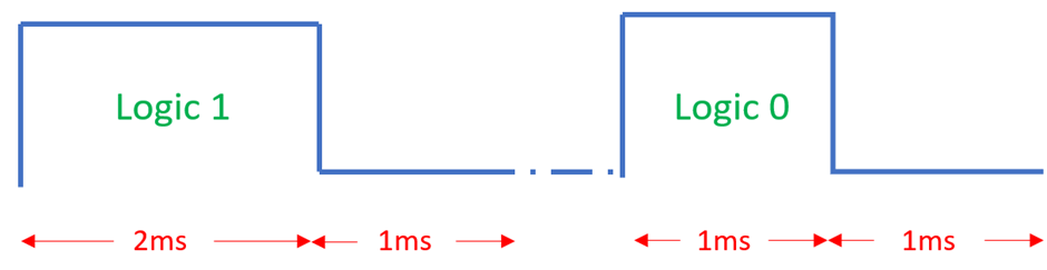
As shown in the illustration above, a “One” is a pulse of 2 ms high followed by a 1 ms low while a “Zero” is a pulse of 1 ms high followed by a 1 ms low pin state. The following function will take RF data byte to be sent via RF module and will convert it to time-slotting pulses. Data is sent from MSB to LSB.
 void RF_send(unsigned char rf_data)
 {
     signed char s = 0x08;

     while(s > 0x00)
     {
          RF_TX = 1;

          if(rf_data & 0x80)
          {
              delay_ms(2);
          }
          else
          {
              delay_ms(1);
          }

          RF_TX = 0;
          delay_ms(1);
          rf_data <<= 1;
          s--;
     }
 }
The above function is just for time-slotting-based bit-banging. However, data that is to be sent needs to be encapsulated in a proper manner so that whatever we send is reliably received by the receiver without any issue. Therefore, we need a mechanism to add a cyclic redundancy check (CRC) along with the data. The following function will accept a byte of data and send it to an RF receiver via an RF medium. There are two steps in between. Generally, an RF receiver module tends to receive a lot of background RF noise due to its default high RF gain setting. Due to this effect, it continuously outputs random pulses even when nothing valid is being transmitted by any transmitter. Thus, a technique is needed to reduce the RF receiver’s gain so that it can pick up the correct transmitted data. This can be achieved by sending a stream of high-frequency pulses. Once the RF gain is reduced, we can reliably send data. However, there could be errors during the reception of data and so a CRC check becomes mandatory. This CRC check would ensure whether the data received is correct or false. The send_data function given below does all of these steps. For simplicity, the CRC here is simply the result of an AND operation between data to be sent and 0xAA.
 void send_data(unsigned char value)
 {
      signed char s = 20;
      unsigned char CRC = 0;

      CRC = (value & 0xAA);

      while(s > 0x00)
      {
            RF_TX = 1;
            delay_us(500);
            RF_TX = 0;
            delay_us(500);
            s--;
      }
      delay_us(100);

      RF_send(value);
      RF_send(CRC);
 }
Now let us look at the receiver side. The receiver side has just to decode and reconstruct what has been sent to it. Since the time-slotting technique has been used to send data, we just have to check pulse widths to determine if received pulses are sync, one or zero pulses. For logic low at the RF RX pin, we have to do nothing. It is only during a logic high that we time the high period. The timing is done in 10µs steps in order to ensure pulse timing accuracy while ensuring that all kinds of pulses are properly polled. A time-keeping variable, t is responsible for keeping time. It gets incremented every 10µs when the RF RX pin is held in the high state. When the RF Rx pin gets low afterward, pulse width time is obtained.
Due to the effects of environment, temperature, medium, oscillator mismatch and other factors, pulse timings may deviate and so all timings are compared in ranges instead of fixed values of 0.5ms, 1ms and 2ms, i.e., there are tolerances in timings. Any pulse that does not fit in these ranges is discarded as a glitch. The receive_data function given below does all of the aforementioned tasks.
 unsigned char receive_data(void)
 {
     unsigned char t = 0;

     while(!RF_RX);
     while(RF_RX)
     {
         t++;
         delay_us(10);
     };

     if((t > 25) && (t < 75))
     {
         return sync;
     }
     else if((t > 175) && (t < 225))
     {
         return 1;
     }
     else if((t > 75) && (t < 125))
     {
         return 0;
     }
     else
     {
         return error;
     }
 }
Now that we understand how the pulses are obtained, we can now focus on how the received pulses are decoded to obtain sent data. Until sync pulses have been successfully obtained, no other received data is processed. If sync pulses have been detected properly then the next 16 bits are polled and the sent data and CRC are reconstructed. At the end of these steps, CRC is calculated and cross-checked against the sent CRC value.
 #define sync               0x09
 #define error              0x06

 ....

 signed long decode_data(void)
 {
     unsigned char d = 0;
     unsigned char s = 0;
     unsigned long value = 0;
     unsigned char v1 = 0;
     unsigned char v2 = 0;

     while(receive_data() != sync);

     d = receive_data();
     while(d == sync)
     {
          d = receive_data();
     };

     while(s < 15)
     {
         switch(d)
         {
             case 1:
             {
                 value |= 1;
                 break;
             }
             case 0:
             {
                 break;
             }
             case sync:
             case error:
             {
                 return -1;
             }
         }
         s++;
         value <<= 1;
         d = receive_data();
     }

     v1 = (value >> 8);
     v2 = (value & 0x00FF);
     delay_ms(4);

     if((v1 & 0xAA) == v2)
     {
         return v1;
     }
     else
     {
         return -1;
     }
 }
In the main code of the transmitter, the value of a variable named value is changed using two onboard push buttons connected to P1.4 and P1.4 and sent every 100ms via RF medium using an RF transmitter module.
 void main(void)
 {
     Init_Device();

     while(1)
     {
         if(INC_SW == 0)
         {
             delay_ms(40);
             value++;
         }

         if(DEC_SW == 0)
         {
             delay_ms(40);
             value--;
         }

         if(value > 200)
         {
             value = 0;
         }

         if(value < 0)
         {
             value = 99;
         }

         send_data(value);
         delay_ms(100);
     };
 }
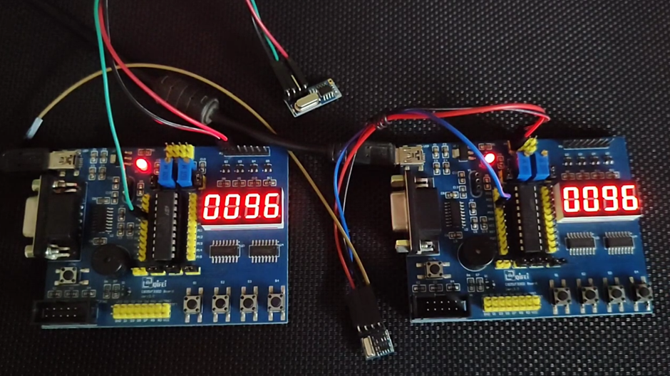
At the receiver side, the value sent by the transmitter is decoded and shown on the onboard seven-segment display.
 void main(void)
 {
     Init_Device();

     while(1)
     {
         value = decode_data();
     };
 }
Demo
|
|
Thanks for the feedback….