Mastering the SiLabs C8051 Microcontroller
|
|
Serial Communication (UART) – HC-SR04 SONAR Reader
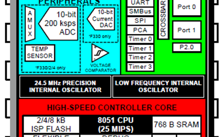
Serial communication via UART peripheral is the most widely used communication method between computers and microcontrollers, portable devices and so on. Many sensors and communication devices such as GSM modems, GPS receivers, RF modules, etc employ UART-based communication to transact data with host devices. UART peripheral is also the backbone of several other communications such as MODBUS, LIN, IrDA and so on.
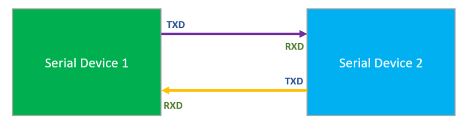
Only a pair of wires along with a ground wire are needed to establish communication between devices. Unless there is a requirement for longer range or voltage-level shifting, no additional hardware is needed to be able to use this peripheral. The following diagram below shows a simplified UART bus.
To learn more about UART visit the following link:
https://learn.mikroe.com/uart-serial-communication
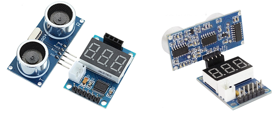
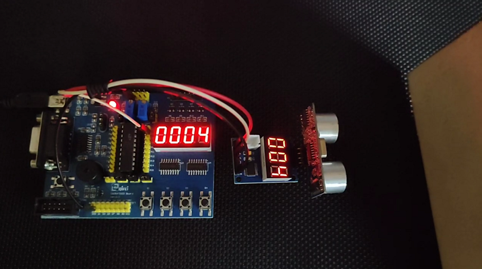
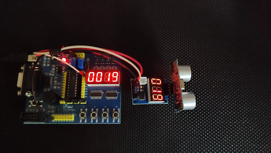
To demonstrate the use of UART peripheral, I used a HC-SR04-to-serial converter. It is also known as a digital tape. This device measures and shows the distance between it and an object facing it using a HC-SR04 ultrasonic SONAR sensor. The extra feature of this device is the measurement output via serial peripherals.
Code
 #define LED_DOUT P1_6_bit
 #define  LED_CLK P1_5_bit
 #define  LED_LATCH P1_7_bit

 unsigned int d = 0;
 unsigned char cnt = 0;
 unsigned char value = 0;
 char rx_buffer[18];

 const unsigned char code segment_code[12] =
 {
   0xC0, // 0
   0xF9, // 1
   0xA4, // 2
   0xB0, // 3
   0x99, // 4
   0x92, // 5
   0x82, // 6
   0xF8, // 7
   0x80, // 8
   0x90, // 9
   0x7F, // .
   0xBF  // -
 };

 const unsigned char code display_pos[4] =
 {
   0xF7, //1st Display
   0xFB, //2nd Display
   0xFD, //3rd Display
   0xFE  //4th Display
 };

 void PCA_Init(void);
 void Timer_Init(void);
 void Port_IO_Init(void);
 void Oscillator_Init(void);
 void Interrupts_Init(void);
 void Init_Device(void);
 void write_74HC595(unsigned char send_data);
 void segment_write(unsigned char disp, unsigned char pos);

 void UART0_ISR(void)
 iv IVT_ADDR_ES0
 ilevel 0
 ics ICS_AUTO
 {
     rx_buffer[cnt++] = UART_Read();
     RI0_bit = 0;
 }

 void Timer_ISR(void)
 iv IVT_ADDR_ET3
 ilevel 1
 ics ICS_AUTO
 {
     switch(i)
     {
         case 0:
         {
             value = (d / 1000);
             break;
         }
         case 1:
         {
             value = ((d % 1000) / 100);
             break;
         }
         case 2:
         {
             value = ((d % 100) / 10);
             break;
         }
         case 3:
         {
             value = (d % 10);
             break;
         }
     }

     if(d >= 40000)
     {
         segment_write(11, i);
     }
     else
     {
         segment_write(value, i);
     }

     i++;

     if(i > 3)
     {
        i = 0;
     }

     TMR3CN &= 0x7F;
 }

 void main(void)
 {
      unsigned char i = 0x00;
      unsigned char j = 0x00;
      unsigned char k = 0x00;
      unsigned char l = 0x00;
      unsigned int multiplier = 1;
      unsigned int range = 0x0000;

      Init_Device();
      UART1_Init(9600);

      while(1)
      {
          if(cnt >= 18)
          {
              for(i = 0; i < 18; i++)
              {
                  if(rx_buffer[i] == 'D')
                  {
                      j = i;
                      j += 2;
                      break;
                  }
              }

              for(i = j; i < 18; i++)
              {
                  if(rx_buffer[i] == ' ')
                  {
                      k = i;
                      break;
                  }
              }

              range = 0;
              multiplier = 1;
              l = ((k - j) - 1);
              for(i = 0; i < l; i++)
              {
                  multiplier *= 10;
              }

              for(i = j; i < k; i++)
              {
                 range += ((rx_buffer[i] - 0x30) * multiplier);
                 multiplier /= 10;
              }

              d = range;
              cnt = 0x00;
          }

          delay_ms(40);
      };
 }

 void PCA_Init(void)
 {
     PCA0MD &= ~0x40;
     PCA0MD = 0x00;
 }

 void Timer_Init(void)
 {
     TMR3CN = 0x04;
     TMR3RLL = 0x02;
     TMR3RLH = 0xFC;
 }

 void Port_IO_Init(void)
 {
     // P0.0  -  Unassigned,  Open-Drain, Digital
     // P0.1  -  Unassigned,  Open-Drain, Digital
     // P0.2  -  Unassigned,  Open-Drain, Digital
     // P0.3  -  Unassigned,  Open-Drain, Digital
     // P0.4  -  TX0 (UART0), Push-Pull,  Digital
     // P0.5  -  RX0 (UART0), Push-Pull,  Digital
     // P0.6  -  Unassigned,  Open-Drain, Digital
     // P0.7  -  Unassigned,  Open-Drain, Digital

     // P1.0  -  Unassigned,  Open-Drain, Digital
     // P1.1  -  Unassigned,  Open-Drain, Digital
     // P1.2  -  Unassigned,  Open-Drain, Digital
     // P1.3  -  Unassigned,  Open-Drain, Digital
     // P1.4  -  Unassigned,  Open-Drain, Digital
     // P1.5  -  Skipped,     Push-Pull,  Digital
     // P1.6  -  Skipped,     Push-Pull,  Digital
     // P1.7  -  Skipped,     Push-Pull,  Digital

     P0MDOUT = 0x30;
     P1MDOUT = 0xE0;
     P1SKIP = 0xE0;
     XBR0 = 0x01;
     XBR1 = 0x40;
 }

 void Oscillator_Init(void)
 {
     OSCICN = 0x82;
 }

 void Interrupts_Init(void)
 {
     IE = 0x90;
     EIE1 = 0x80;
 }

 void Init_Device(void)
 {
     PCA_Init();
     Timer_Init();
     Port_IO_Init();
     Oscillator_Init();
     Interrupts_Init();
 }

 void write_74HC595(unsigned char send_data)
 {
     signed char clks = 0x08;

     while(clks > 0)
     {
         if((send_data & 0x80) == 0x00)
         {
           LED_DOUT = 0;
         }
         else
         {
           LED_DOUT = 1;
         }

         LED_CLK = 0;
         send_data <<= 1;
         clks--;
         LED_CLK = 1;
     }
 }

 void segment_write(unsigned char disp, unsigned char pos)
 {
     LED_LATCH = 0;
     write_74HC595(segment_code[disp]);
     write_74HC595(display_pos[pos]);
     LED_LATCH = 1;
 }
Schematic
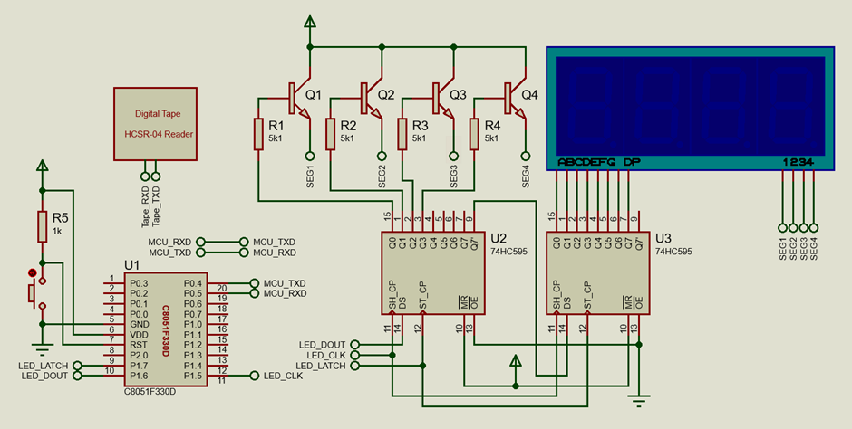
Explanation
To simplify things, the MikroC compiler’s UART library is used in this example. The rest of the setup is just like all other examples. Thus, we can focus on data processing and working of the UART peripheral.
 Init_Device();
 UART1_Init(9600);
The digital tape provides distance in the following string format at a baud rate of 9600 bps:
D:XXX\r\n
Thus, the UART of C8051F330 has to read 8 bytes (7 actually and a null character) of data. Interrupt-based data acquisition is used because this method not only frees up the main loop but also addresses the fact that no one knows when and from which part of data would be transmitted and received.
Firstly, a global data buffer is needed that would store any data received by the UART reception interrupt. This buffer should be larger than the actual number of data bytes that would be received and this is so to accommodate at least two successive transmissions from the tape. At every interrupt, the UART is read and the buffer is filled sequentially.
 char rx_buffer[18];

 ....

 void UART0_ISR(void)
 iv IVT_ADDR_ES0
 ilevel 0
 ics ICS_AUTO
 {
     rx_buffer[cnt++] = UART_Read();
     RI0_bit = 0;
 }
When the buffer inside the interrupt is full, the code starts searching for the string of characters as per the mentioned format the tape is supposed to send. Once the character “D” is found, the code then searches for numeric characters before null character. The numeric characters are then converted to numbers and the distance is computed and shown on the display.
 void main(void)
 {
      unsigned char i = 0x00;
      unsigned char j = 0x00;
      unsigned char k = 0x00;
      unsigned char l = 0x00;
      unsigned int multiplier = 1;
      unsigned int range = 0x0000;

      Init_Device();
      UART1_Init(9600);

      while(1)
      {
          if(cnt >= 18)
          {
              for(i = 0; i < 18; i++)
              {
                  if(rx_buffer[i] == 'D')
                  {
                      j = i;
                      j += 2;
                      break;
                  }
              }
              for(i = j; i < 18; i++)
              {
                  if(rx_buffer[i] == ' ')
                  {
                      k = i;
                      break;
                  }
              }

              range = 0;
              multiplier = 1;
              l = ((k - j) - 1);
              for(i = 0; i < l; i++)
              {
                  multiplier *= 10;
              }
              for(i = j; i < k; i++)
              {
                 range += ((rx_buffer[i] - 0x30) * multiplier);
                 multiplier /= 10;
              }

              d = range;
              cnt = 0x00;
          }

          delay_ms(40);
      };
 }
Demo
|
|
Thanks for the feedback….