Mastering the SiLabs C8051 Microcontroller
|
|
Timer (TMR) – Countdown Timer
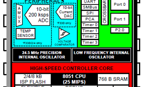
In digital electronics and embedded systems, timing is literally everything and so this makes timers of any microcontroller very important. The C8051F330D microcontroller has 4 timers – Timer 0 to Timer 3.
Timers 0 and 1 are similar to the ones we would expect with any standard 8051 microcontrollers. They can be used as timers or counters. In counter mode, these timers can count external pulses/inputs.
Timers 2 and 3 are additional timers and they have the same features and similar operating procedures. These timers cannot be used as counters.
Timers are the clock source for some internal hardware peripherals such as UARTs and SMBUS. All of these timers can be clocked with various clock sources. The table shown below summarizes the mode of operation of all of these timers.
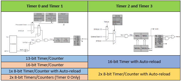
All of these timers can be configured in various ways and at that moment things get complex. Fortunately for us, SiLabs’ Configuration Wizard 2 makes coding a lot easy as it takes care of setting these timers just like other hardware peripherals.
Code
 #define LED_DOUT           P1_6_bit
 #define LED_CLK            P1_5_bit
 #define LED_LATCH          P1_7_bit

 #define SET                P1_4_bit
 #define INC                P1_3_bit
 #define DEC                P1_2_bit
 #define ESC                P1_1_bit

 unsigned char i = 0;
 register unsigned char val = 0;
 signed int s = 0;
 unsigned int ms = 0;

 const unsigned char code segment_code[12] =
 {
   0xC0, // 0
   0xF9, // 1
   0xA4, // 2
   0xB0, // 3
   0x99, // 4
   0x92, // 5
   0x82, // 6
   0xF8, // 7
   0x80, // 8
   0x90, // 9
   0x7F, // .
   0xBF  // -
 };

 const unsigned char code display_pos[4] =
 {
   0xF7, //1st Display
   0xFB, //2nd Display
   0xFD, //3rd Display
   0xFE  //4th Display
 };

 void PCA_Init(void);
 void Timer_Init(void);
 void Port_IO_Init(void);
 void Oscillator_Init(void);
 void Interrupts_Init(void);
 void Init_Device(void);
 void data_converter(unsigned int val);
 void write_74HC595(unsigned char send_data);
 void segment_write(unsigned char disp, unsigned char pos);

 void Timer_2_ISR(void)
 iv IVT_ADDR_ET2
 ilevel 1
 ics ICS_AUTO
 {
     ms++;
     if(ms > 999)
     {
         ms = 0;
         s--;

         if(s < 0)
         {
            s = 0;
            TR2_bit = 0;
         }
     }

     TMR2CN &= 0x7F;
 }

 void Timer_3_ISR(void)
 iv IVT_ADDR_ET3
 ilevel 0
 ics ICS_AUTO
 {
     switch(i)
     {
         case 0:
         {
             val = (s / 1000);
             break;
         }
         case 1:
         {
             val = ((s % 1000) / 100);
             break;
         }
         case 2:
         {
             val = ((s % 100) / 10);
             break;
         }
         case 3:
         {
             val = (s % 10);
             break;
         }
     }

     segment_write(val, i);

     i++;

     if(i > 3)
     {
        i = 0;
     }

     TMR3CN &= 0x7F;
 }

 void main(void)
 {
   unsigned char set_time = 0;
   Init_Device();

   while(1)
   {
       if(SET == 0)
       {
          delay_ms(40);
          while(SET == 0);

          set_time = 1;
       }

       if(set_time == 1)
       {
           if(INC == 0)
           {
              delay_ms(40);
              s++;

              if(s >= 9999)
              {
                  s = 9999;
              }
           }

           if(DEC == 0)
           {
              delay_ms(40);
              s--;

              if(s <= 0)
              {
                  s = 0;
              }
           }

           if(ESC == 0)
           {
              TR2_bit = 1;
              set_time = 0;
           }
       }
   };
 }

 void PCA_Init(void)
 {
     PCA0MD &= ~0x40;
     PCA0MD = 0x00;
 }

 void Timer_Init(void)
 {
     TMR2RLL = 0x02;
     TMR2RLH = 0xFC;
     TMR3CN = 0x04;
     TMR3RLL = 0x02;
     TMR3RLH = 0xFC;
 }

 void Port_IO_Init(void)
 {
     // P0.0  -  Unassigned,  Open-Drain, Digital
     // P0.1  -  Unassigned,  Open-Drain, Digital
     // P0.2  -  Unassigned,  Open-Drain, Digital
     // P0.3  -  Unassigned,  Open-Drain, Digital
     // P0.4  -  Unassigned,  Open-Drain, Digital
     // P0.5  -  Unassigned,  Open-Drain, Digital
     // P0.6  -  Unassigned,  Open-Drain, Digital
     // P0.7  -  Unassigned,  Open-Drain, Digital

     // P1.0  -  Unassigned,  Open-Drain, Digital
     // P1.1  -  Skipped,     Open-Drain, Digital
     // P1.2  -  Skipped,     Open-Drain, Digital
     // P1.3  -  Skipped,     Open-Drain, Digital
     // P1.4  -  Skipped,     Open-Drain, Digital
     // P1.5  -  Skipped,     Push-Pull,  Digital
     // P1.6  -  Skipped,     Push-Pull,  Digital
     // P1.7  -  Skipped,     Push-Pull,  Digital

     P1MDOUT = 0xE0;
     P1SKIP = 0xFE;
     XBR1 = 0x40;
 }

 void Oscillator_Init(void)
 {
     OSCICN = 0x82;
 }

 void Interrupts_Init(void)
 {
     IE = 0xA0;
     EIE1 = 0x80;
 }

 void Init_Device(void)
 {
     PCA_Init();
     Timer_Init();
     Port_IO_Init();
     Oscillator_Init();
     Interrupts_Init();
     LED_LATCH = 1;
     LED_CLK = 1;
     LED_DOUT = 0;
 }

 void write_74HC595(unsigned char send_data)
 {
     signed char clks = 8;

     while(clks > 0)
     {
         if((send_data & 0x80) == 0x00)
         {
           LED_DOUT = 0;
         }
         else
         {
           LED_DOUT = 1;
         }

         LED_CLK = 0;
         send_data <<= 1;
         clks--;
         LED_CLK = 1;
     }
 }

 void segment_write(unsigned char disp, unsigned char pos)
 {
     LED_LATCH = 0;
     write_74HC595(segment_code[disp]);
     write_74HC595(display_pos[pos]);
     LED_LATCH = 1;
 }
Schematic
Explanation
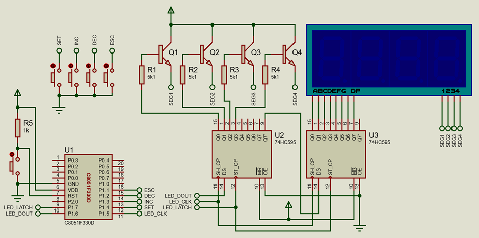
In this demo, two timers – Timer 2 and 3 have been used to make a simple countdown timer. Timer 3 is used for multiplexing the onboard seven-segment displays while Timer 2 is used as the actual countdown timer.
First, let’s see how the multiplexing is achieved. With reference to the schematic, the seven-segment displays are driven with a pair of 74HC595 serial-in-parallel-out (SIPO) shift registers. The shift registers are cascaded in series. This means that the final output of the first shift register is connected to the data input of the second shift register while clock and latch pins are shorted. With this configuration, we get a 16-bit wide shift register because the first shift register would shift out data to the second register. Using shift registers in this way allows us to expand three outputs from C8051F330D to literally unlimited number of outputs. Here we just need 16 outputs.
 void write_74HC595(unsigned char send_data)
 {
     signed char clks = 8;

     while(clks > 0)
     {
         if((send_data & 0x80) == 0x00)
         {
           LED_DOUT = 0;
         }
         else
         {
           LED_DOUT = 1;
         }

         LED_CLK = 0;
         send_data <<= 1;
         clks--;
         LED_CLK = 1;
     }
 }
74HC595 SIPO registers take data serially in and the input data is shifted when there is a low to high clock transition. One shift register can hold up to 8 bits or one byte of data and so eight clock transitions are needed. The above function does this SIPO part.
Now that we know how to transfer data through the shift registers, we can now focus on how the seven segments are lit. The first eight bits are used to select which seven-segment out of the four to be lit and the second eight bits following it write the code for the LEDs of the selected segment. After sending these two bytes, the shift registers are latched by raising their latch pins high from low, meaning that all outputs of the shift registers are updated.
 #define LED_DOUT           P1_6_bit
 #define LED_CLK            P1_5_bit
 #define LED_LATCH          P1_7_bit

 ....

 const unsigned char code segment_code[12] =
 {
   0xC0, // 0
   0xF9, // 1
   0xA4, // 2
   0xB0, // 3
   0x99, // 4
   0x92, // 5
   0x82, // 6
   0xF8, // 7
   0x80, // 8
   0x90, // 9
   0x7F, // .
   0xBF  // -
 };

 const unsigned char code display_pos[4] =
 {
   0xF7, //1st Display
   0xFB, //2nd Display
   0xFD, //3rd Display
   0xFE  //4th Display
 };

 ....

 void segment_write(unsigned char disp, unsigned char pos)
 {
     LED_LATCH = 0;
     write_74HC595(segment_code[disp]);
     write_74HC595(display_pos[pos]);
     LED_LATCH = 1;
 }
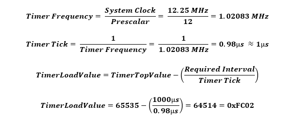
The above code just writes one seven-segment display at a time but we have four seven-segment displays. All of them need to be updated in such a way that all of them appear to be displayed simultaneously at the same time. Therefore, they need to be updated at a fast refresh rate and in such a way that while updating them no other tasks are blocked. To achieve this, we need a timer with periodic interrupts. Here Timer 3 is used with about a 1ms periodic interrupt interval. The following math shows how to find the ideal timer auto-reload value to achieve the desired timer interrupt interval. Remember that Timer 3 has an auto-reload feature and so we just have to put the calculated value in our code once.
The code below shows the timer, system clock and interrupt settings generated by the Configuration Wizard 2 code generator.
 void Timer_Init(void)
 {
     TMR2RLL = 0x02;
     TMR2RLH = 0xFC;
     TMR3CN = 0x04;
     TMR3RLL = 0x02;
     TMR3RLH = 0xFC;
 }


 void Oscillator_Init(void)
 {
     OSCICN = 0x82;
 }


 void Interrupts_Init(void)
 {
     IE = 0xA0;
     EIE1 = 0x80;
 }
Inside Timer 3 interrupt, the value to be displayed by the seven segments are decoded bytewise and position-wise and the respective seven segment displays are updated. This process is repeated periodically every 1ms.
 void Timer_3_ISR(void)
 iv IVT_ADDR_ET3
 ilevel 0
 ics ICS_AUTO
 {
     switch(i)
     {
         case 0:
         {
             val = (s / 1000);
             break;
         }
         case 1:
         {
             val = ((s % 1000) / 100);
             break;
         }
         case 2:
         {
             val = ((s % 100) / 10);
             break;
         }
         case 3:
         {
             val = (s % 10);
             break;
         }
     }

     segment_write(val, i);

     i++;

     if(i > 3)
     {
        i = 0;
     }

     TMR3CN &= 0x7F;
 }
Timer 2 is set just like Timer 3 and for 1ms interrupt interval but unlike Timer 3, it is not left to run by default. This is so because we want the timer to run after we have set the countdown time in seconds. In the main loop, four onboard push buttons are used to set count down time and start the timer.
 while(1)
 {
     if(SET == 0)
     {
        delay_ms(40);
        while(SET == 0);

        set_time = 1;
     }

     if(set_time == 1)
     {
         if(INC == 0)
         {
            delay_ms(40);
            s++;

            if(s >= 9999)
            {
                s = 9999;
            }
         }

         if(DEC == 0)
         {
            delay_ms(40);
            s--;

            if(s <= 0)
            {
                s = 0;
            }
         }

         if(ESC == 0)
         {
            TR2_bit = 1;
            set_time = 0;
         }
     }
 };
Inside the interrupt subroutine of Timer 2, a pair of variables keep track of milliseconds and seconds. Upon every 1000ms (1s) count, the countdown second is decremented. The timer keeps running till the second count has reached zero. When the second count has reached zero the timer is stopped by clearing its timer run flag bit.
 void Timer_2_ISR(void)
 iv IVT_ADDR_ET2
 ilevel 1
 ics ICS_AUTO
 {
     ms++;
     if(ms > 999)
     {
         ms = 0;
         s--;

         if(s < 0)
         {
            s = 0;
            TR2_bit = 0;
         }
     }

     TMR2CN &= 0x7F;
 }
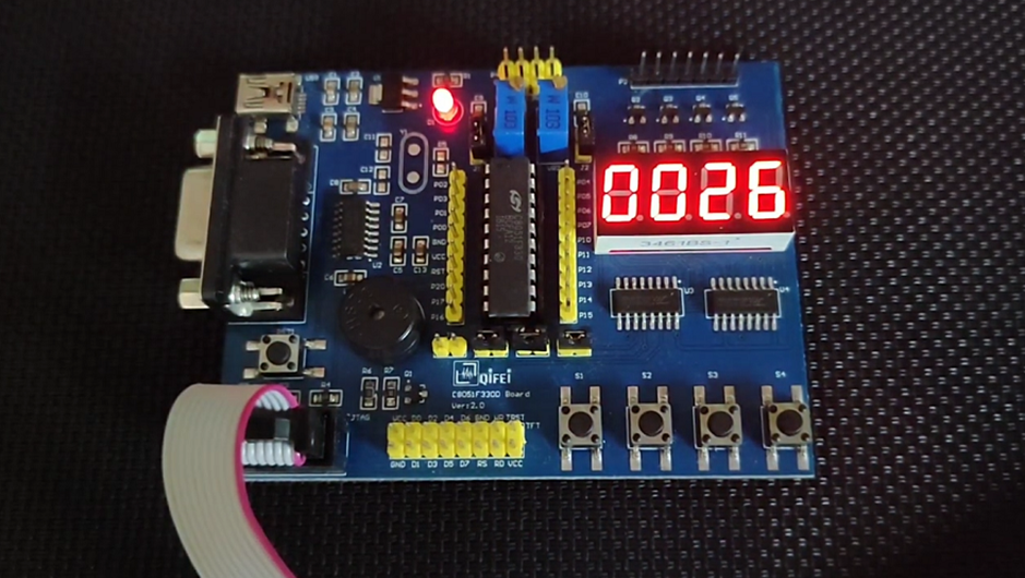
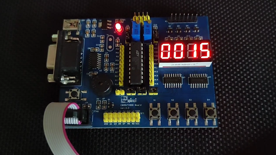
Demo
|
|
Thanks for the feedback….