Mastering the SiLabs C8051 Microcontroller
|
|
Digital-to-Analogue Converter (IDA0) – Digital Signal Synthesizer
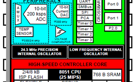
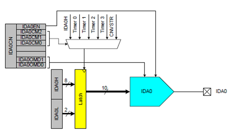
Digital-to-Analogue Converter (DAC) is just the converse hardware with respect to the ADC. With the exception of ARM microcontrollers and some modern microcontrollers such as the ATXMega series, DAC is not present in common devices and we have to use external DAC chips like the MCP4921 if we need one in a project. Fortunately, C8051F330D has one 10-bit DAC which can be used for a number of applications including audio generation, waveform generation, etc. Unlike most DACs which provide voltage outputs, the DAC present in C8051F330D provides current output instead of voltage output. With a suitable load resistor, we can convert the output current from the DAC to voltage. The block diagram below shows the contents of the DAC. The DAC can be triggered by a number of sources including all timers. These trigger sources are used to update DAC output. Two registers hold the 10-bit digital count that would be converted to current. The digital count is latched upon trigger. Through register coding, it is also possible to set the maximum full-scale current which can be 0.5mA, 1.0mA or 2.0mA.
Code
 #define LED_DOUT          P1_6_bit
 #define LED_CLK           P1_5_bit
 #define LED_LATCH         P1_7_bit

 #define MODE_SW           P1_3_bit
 #define INC_SW            P1_2_bit
 #define DEC_SW            P1_1_bit

 unsigned char i = 0;
 register unsigned char val = 0;
 unsigned int value = 0;

 const unsigned char code segment_code[12] =
 {
   0xC0, // 0
   0xF9, // 1
   0xA4, // 2
   0xB0, // 3
   0x99, // 4
   0x92, // 5
   0x82, // 6
   0xF8, // 7
   0x80, // 8
   0x90, // 9
   0x7F, // .
   0xBF  // -
 };

 const unsigned char code display_pos[4] =
 {
   0xF7, //1st Display
   0xFB, //2nd Display
   0xFD, //3rd Display
   0xFE  //4th Display
 };

 const unsigned int code LUT_sine[32] =
 {
     512,
     615,
     714,
     804,
     882,
     946,
     991,
     1017,
     1023,
     1007,
     971,
     916,
     845,
     760,
     665,
     564,
     460,
     359,
     264,
     179,
     108,
     53,
     17,
     2,
     7,
     33,
     78,
     142,
     220,
     310,
     409,
     512
 };

 const unsigned int code LUT_triangle[32] =
 {
     512,
     576,
     640,
     704,
     768,
     832,
     896,
     960,
     1023,
     960,
     896,
     832,
     768,
     704,
     640,
     576,
     512,
     448,
     384,
     320,
     256,
     192,
     128,
     64,
     0,
     64,
     128,
     192,
     256,
     320,
     384,
     448
 };

 const unsigned int code LUT_square[32] =
 {
     0,
     0,
     0,
     0,
     0,
     0,
     0,
     0,
     0,
     0,
     0,
     0,
     0,
     0,
     0,
     0,
     1023,
     1023,
     1023,
     1023,
     1023,
     1023,
     1023,
     1023,
     1023,
     1023,
     1023,
     1023,
     1023,
     1023,
     1023,
     1023
 };

 void PCA_Init(void);
 void Timer_Init(void);
 void DAC_Init(void);
 void Port_IO_Init(void);
 void Oscillator_Init(void);
 void Interrupts_Init(void);
 void Init_Device(void);
 void write_74HC595(unsigned char send_data);
 void segment_write(unsigned char disp, unsigned char pos);
 void DAC_write(unsigned int dac_value);

 void Timer_ISR(void)
 iv IVT_ADDR_ET3
 ilevel 0
 ics ICS_AUTO
 {
     switch(i)
     {
         case 0:
         {
             val = (value / 1000);
             break;
         }
         case 1:
         {
             val = ((value % 1000) / 100);
             break;
         }
         case 2:
         {
             val = ((value % 100) / 10);
             break;
         }
         case 3:
         {
             val = (value % 10);
             break;
         }
     }

     segment_write(val, i);

     i++;

     if(i > 3)
     {
        i = 0;
     }

     TMR3CN &= 0x7F;
 }

 void main(void)
 {
     signed char l = 0;
     unsigned int j = 0;
     signed int dly = 0;
     unsigned int dac_data = 0;
     unsigned char mode = 0;

     Init_Device();

     while(1)
     {
         if(MODE_SW == 0)
         {
             delay_ms(30);
             l = 0;
             dac_data = 0;
             mode++;
         }

         if(mode >= 3)
         {
             mode = 0;
         }

         if(INC_SW == 0)
         {
             delay_ms(40);
             dly++;
         }

         if(dly > 9999)
         {
             dly = 0;
         }

         if(DEC_SW == 0)
         {
             delay_ms(40);
             dly--;
         }

         if(dly < 0)
         {
             dly = 9999;
         }

         value = dly;

         switch(mode)
         {
             case 1:
             {
                 dac_data = LUT_triangle[l];
                 break;
             }

             case 2:
             {
                 dac_data = LUT_square[l];
                 break;
             }

             default:
             {
                 dac_data = LUT_sine[l];
                 break;
             }
         }

         l++;
         if(l >= 32)
         {
            l = 0;
         }

         DAC_write(dac_data);

         for(j = 0; j < dly; j++)
         {
             delay_us(1);
         }
     };
 }

 void PCA_Init(void)
 {
     PCA0MD &= ~0x40;
     PCA0MD = 0x00;
 }

 void Timer_Init(void)
 {
     TMR3CN = 0x04;
     TMR3RLL = 0x02;
     TMR3RLH = 0xFC;
 }

 void DAC_Init(void)
 {
     IDA0CN = 0xF2;
 }

 void Port_IO_Init(void)
 {
     // P0.0  -  Unassigned,  Open-Drain, Digital
     // P0.1  -  Skipped,     Open-Drain, Analog
     // P0.2  -  Unassigned,  Open-Drain, Digital
     // P0.3  -  Unassigned,  Open-Drain, Digital
     // P0.4  -  Unassigned,  Open-Drain, Digital
     // P0.5  -  Unassigned,  Open-Drain, Digital
     // P0.6  -  Unassigned,  Open-Drain, Digital
     // P0.7  -  Unassigned,  Open-Drain, Digital

     // P1.0  -  Unassigned,  Open-Drain, Digital
     // P1.1  -  Skipped,     Open-Drain, Digital
     // P1.2  -  Skipped,     Open-Drain, Digital
     // P1.3  -  Skipped,     Open-Drain, Digital
     // P1.4  -  Unassigned,  Open-Drain, Digital
     // P1.5  -  Skipped,     Push-Pull,  Digital
     // P1.6  -  Skipped,     Push-Pull,  Digital
     // P1.7  -  Skipped,     Push-Pull,  Digital

     P0MDIN = 0xFD;
     P1MDOUT = 0xE0;
     P0SKIP = 0x02;
     P1SKIP = 0xEE;
     XBR1 = 0x40;
 }

 void Oscillator_Init(void)
 {
     OSCICN = 0x82;
 }

 void Interrupts_Init(void)
 {
     IE = 0x80;
     EIE1 = 0x80;
 }

 void Init_Device(void)
 {
     PCA_Init();
     Timer_Init();
     DAC_Init();
     Port_IO_Init();
     Oscillator_Init();
     Interrupts_Init();
 }

 void write_74HC595(unsigned char send_data)
 {
     signed char clks = 8;

     while(clks > 0)
     {
         if((send_data & 0x80) == 0x00)
         {
           LED_DOUT = 0;
         }
         else
         {
           LED_DOUT = 1;
         }

         LED_CLK = 0;
         send_data <<= 1;
         clks--;
         LED_CLK = 1;
     }
 }

 void segment_write(unsigned char disp, unsigned char pos)
 {
     LED_LATCH = 0;
     write_74HC595(segment_code[disp]);
     write_74HC595(display_pos[pos]);
     LED_LATCH = 1;
 }

 void DAC_write(unsigned int dac_value)
 {
     unsigned char lb = 0x00;
     unsigned char hb = 0x00;

     dac_value <<= 0x06;

     lb = (dac_value & 0xC0);
     hb = ((dac_value & 0xFF00) >> 0x08);

     IDA0L = lb;
     IDA0H = hb;
 }
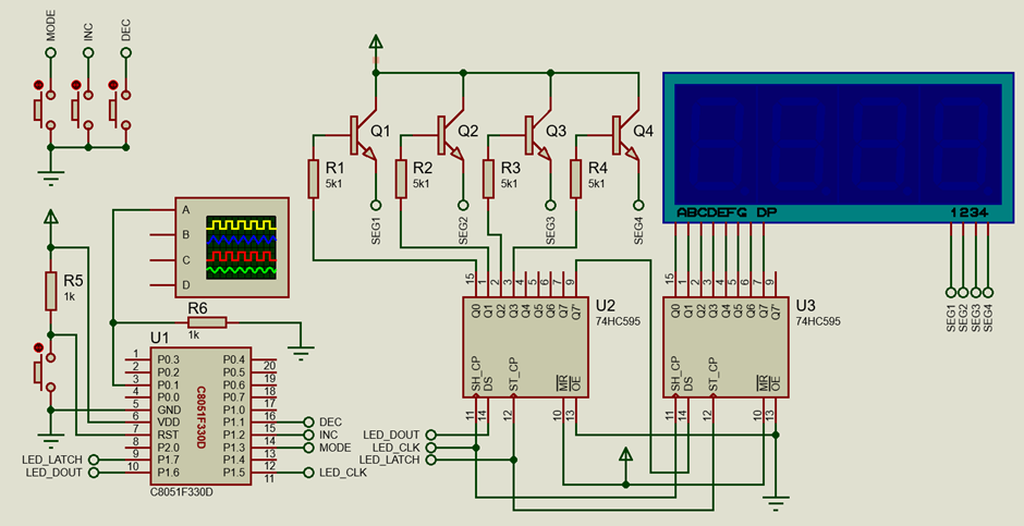
Schematic
Explanation
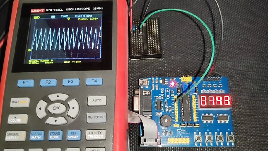
In this example, the internal DAC is used to generate waveforms digitally – sinusoidal, triangular and square waves. The result is a Digital Signal Synthesizer (DSS).
Firstly, the system clock is set to 12.25MHz and is derived from internal oscillator.
 void Oscillator_Init(void)
 {
     OSCICN = 0x82;
 }
C8051’s DAC is set up just by setting the IDA0CN register. We need to enable the DAC, define its full-scale current value, and the source that would issue a new write sequence and the output pin.
 void DAC_Init(void)
 {
     IDA0CN = 0xF2;
 }
The DAC takes 10-bit integer inputs that are separated by two registers and so we need a function to load these registers. This is done by the following function. Notice how the two registers are arranged and loaded.

 void DAC_write(unsigned int dac_value)
 {
     unsigned char lb = 0x00;
     unsigned char hb = 0x00;

     dac_value <<= 0x06;

     lb = (dac_value & 0xC0);
     hb = ((dac_value & 0xFF00) >> 0x08);

     IDA0L = lb;
     IDA0H = hb;
 }
Three lookup table arrays for three types of waveforms hold the 10-bit values that would be put into the DAC input register. Alternatively, equations could have been used but that would require mathematical computations and would slow down the wave-generation process.
 const unsigned int code LUT_sine[32] =
 {
     512,
     615,
     714,
     804,
     882,
     946,
     991,
     1017,
     1023,
     1007,
     971,
     916,
     845,
     760,
     665,
     564,
     460,
     359,
     264,
     179,
     108,
     53,
     17,
     2,
     7,
     33,
     78,
     142,
     220,
     310,
     409,
     512
 };

 const unsigned int code LUT_triangle[32] =
 {
     512,
     576,
     640,
     704,
     768,
     832,
     896,
     960,
     1023,
     960,
     896,
     832,
     768,
     704,
     640,
     576,
     512,
     448,
     384,
     320,
     256,
     192,
     128,
     64,
     0,
     64,
     128,
     192,
     256,
     320,
     384,
     448
 };

 const unsigned int code LUT_square[32] =
 {
     0,
     0,
     0,
     0,
     0,
     0,
     0,
     0,
     0,
     0,
     0,
     0,
     0,
     0,
     0,
     0,
     1023,
     1023,
     1023,
     1023,
     1023,
     1023,
     1023,
     1023,
     1023,
     1023,
     1023,
     1023,
     1023,
     1023,
     1023,
     1023
 };
Three buttons are used to control the DSS. Pressing the button attached to P1.3 switches waveform types while pressing the buttons connected to P1.1 and P1.2 changes the frequency of the output waveform. This is the task inside the main loop. The onboard display gives an indication of period.
 void main(void)
 {
     signed char l = 0;
     unsigned int j = 0;
     signed int dly = 0;
     unsigned int dac_data = 0;
     unsigned char mode = 0;

     Init_Device();

     while(1)
     {
         if(MODE_SW == 0)
         {
             delay_ms(30);
             l = 0;
             dac_data = 0;
             mode++;
         }

         if(mode >= 3)
         {
             mode = 0;
         }

         if(INC_SW == 0)
         {
             delay_ms(40);
             dly++;
         }

         if(dly > 9999)
         {
             dly = 0;
         }

         if(DEC_SW == 0)
         {
             delay_ms(40);
             dly--;
         }

         if(dly < 0)
         {
             dly = 9999;
         }

         value = dly;

         switch(mode)
         {
             case 1:
             {
                 dac_data = LUT_triangle[l];
                 break;
             }

             case 2:
             {
                 dac_data = LUT_square[l];
                 break;
             }

             default:
             {
                 dac_data = LUT_sine[l];
                 break;
             }
         }

         l++;
         if(l >= 32)
         {
            l = 0;
         }

         DAC_write(dac_data);

         for(j = 0; j < dly; j++)
         {
             delay_us(1);
         }
     };
 }
Demo
|
|
Thanks for the feedback….